Page is loading ...

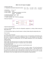
TC-920Ri
CONTROLLER FOR REFRIGERATION
AND DEFROST WITH DIGITAL INPUT
2. APPLICATION
3. TECHNICAL SPECIFICATIONS
• Counters
• Refrigerating balconies
90 - 250Vac ±10%(50/60Hz)
0 to 50°C / 32 to 122°F
10 to 90% RH (without condensation)
0.1°C from -10 to 75°C and 1°C outside this range
1°F in wall range
REFR: 5(3)A/ 250Vac 1/8HP (compressor, solenoid valve or contactor)
FANS: 5(3)A / 250Vac1/8HP (evaporator fans)
DEFR: 3A/ 250Vac (defrost - resistance or hot gas)
- Power supply:
Operating temperature:
- Operating humidity:
- Resolution:
- Load current (outputs):
-
4. CONFIGURATIONS
4.1 - Control temperatures adjust (SETPOINTS):
- Press for 2 seconds until appears , and release it after that. It will appear and the
working temperature adjusted. Use and keys to change the value and then press to
record it. Soon after it (economic setpoint ) will appear, if configured on F33, repeats the
procedure above to modify the value and leave the function.
- Dimensions:
- Sensors:
71 x 28 x 71mm
S1: Room sensor (inflating / inlet air) - Black cable - Follow the product
S2: Evaporator sensor - Gray cable - Follow the product
S3: Sensor with configurable position (Room - Return / outlet air, 2nd evaporator or condenser)
- Sensor 3 sold separately.
SET
SET
4.2 - Parameters table
4.3 - Parameters description
F01 -Access code (123)
F02 - Control differential (hysteresis)
F03 - Offset indication of room sensor (Offset S1)
F04 - Offset indication of evaporator sensor (Offset S2)
F05 - Offset indication of sensor S3 (Offset S3)
F06 - Mini
F08 - Delay when the instrument is powered on
F09 - Refrigeration time (interval between defrosts)
F10 - Minimum compress
To change the parameters it is necessary to use the access code.It is not necessary to use the access
code to visualize the adjusted parameters.
It is the difference of temperature (hysteresis) between to turn OFF and turn ON the refrigeration output.
Example: To control the temperature in 4.0°C with differential of 1.0°C. Soon, the refrigeration will be
turned off in 4.0°C and turned on again in 5.0°C (4.0 + 1.0)
It allows to compensate eventual shunting lines in the reading of room temperature (S1) proceeding
from the exchange of the sensor or cable length alteration
It allows to compensate eventual shunting lines in the reading of evaporator temperature (S2)
proceeding from the exchange of the sensor or cable length alteration
It allows to compensate eventual shunting lines in the reading of room temperature (S3) proceeding
from the exchange of the sensor or cable length alteration
When the instrument is powered on, its control is kept disabled during a time, delaying the start of
process. During this time, it works only as temperature indicator. It serves to prevent demand of electric
energy peaks, in case of lack or return of the same and when exists a lot of equipment connected on the
same net. For this, just adjust different times for each equipment. This delay may be of compressor or
defrost (when exist defrost on turn on).
It is the time which compressor will turn on and turn off only for room temperature and starts to be
counted when the fan is turned on , after fan-delay stage (fan return after draining).
Attention, defrost will begin only if the temperature in S2 (evaporator sensor) is lower than the indicated
in F14.
It is the minimum time that the compressor will keep turned on, it means, the time period between the last
started and the next stopped. It serves to prevent high voltage from the mains.
mum setpoint allowed to the end user
F07 - Maximum setpoint allowed to the end user
or time ON
Electronic limits whose purpose is prevent that too high or too low setpoint temperatures are regulated.
1. DESCRIPTION
The is a temperature controller device for the frozen food industry, which can also be
used to control the evaporator fan and to manage the defrosting cycles.
It works with up to 3 sensors, two of them are for room temperature measurement (air inlet and air return)
and the third one can be fixed in the evaporator to control the ending of defrosting operation and
returning of fan operation. It is possible to configure the third sensor in order to control the temperature in
the condenser or to control another evaporator.
It also includes a digital input to receive external pulses for controlling the start of defrosting operation or
for monitoring the chamber door status.
Aiming to reduce the power consumption, the allows the configuration of two setpoints:
normal and power saving. This is possible when the third sensor is used for measuring the return air
temperature, which allows the selection of active setpoint based on the temperature difference between
the inlet air sensor and the return air sensor (S3 - S1).
When the difference between the sensors is above the value configured by the user (high level of
thermal exchange), the active setpoint is the normal (SP1). When the difference between the sensor is
below another value also configured by the user (low level of thermal exchange), the active setpoint is
the Power Saving (SP2), which must be configured to a temperature higher than SP1 in order to reduce
the compressor ON time, which in turn decreases the electric power consumption.
Product complies with ULInc. (United States and Canada).
TC-920Ri
TC-920Ri
E251415
Ver.04
REFR
FANS
TC-920Ri
DEFR
BUZZ
-99
0.1
-20
-20
-20
-50
-50
0
1
0
0
0 - OFF
0 -
-50
No
inactive0 -
999
20.0
20.0
20.0
20.0
75.0
75.0
30
999
999
999
1 - ON
1 - Yes
75.0
90
-
°C
°C
°C
°C
°C
°C
min.
min.
sec.
sec.
-
-
°C
min.
-
1
-36
-36
-36
-58
-58
0
1
0
0
0 -
-58
0 -
0 - OFF
No
inactive
-
36
36
36
36
167
167
30
999
999
999
1 - ON
1 -
167
90
ON
-
°F
°F
°F
°F
°F
°F
min.
min.
sec.
sec.
-
-
°F
min.
-
3
0
0
0
-58
167
0
240
0
0
1
0
104
45
CELSIUS
FAHRENHEIT
-
1.5
0
0
0
-50
75.0
0
240
0
0
1
0
40.0
45
Min
Max
Unid
Default
Min
Max
Unid
Default
0 - No
0
0 - No
0
-50
0
0 - No
-50
0
-50
0.1
-50
0.1
0
1 - Yes
1
1 - Yes
30
75.0
30
1 - Yes
75.0
4
75.0
20.0
75.0
20.0
999
0 - No
0
0 - No
0
-58
0
0 - No
-58
0
-58
1
-58
1
0
1 - Yes
1
1 - Yes
30
167
30
1 - Yes
167
4
167
36
167
36
999
0
0
0
10
32
1
1
167
0
-58
2
167
2
0
0
0
0
10
0.0
1
1 - Yes
75.0
0
-50
1
75.0
1.0
0
- No
- No
DescriptionFun
Access code:123 (one hundred and twenty-three)
Control differential (hysteresis)
Offset indication of room sensor (Offset S1)
Offset indication of evaporator sensor (Offset S2)
Offset indication of sensor S3 (Offset S3)
Minimum setpoint allowed to the end user
Maximum setpoint allowed to the end user
Delay when the instrument is powered on
Refrigeration time (interval between defrosts)
Minimum time ON
Minimum time OFF
Compressor status with detached room sensor (S1)
Defrost when the instrument is powered on
Evaporator temperature (S2 / S3*) for end of defrost
Maximum duration of defrost
compressor
compressor
determine
Fan turned on during defrost
Defrost type (0 - electric / 1 - hot gas)
Locked temperature indication (S1) during defrost
Draining time (dripping of defrost water)
Evaporator temperature (S2) for fan return after draining
Maximum time of fan return after draining (fan-delay)
Fan on with compressor off (refrigeration)
Fan stopped for high temperature in the evaporator
Operation mode of digital input
Low ambient temperature alarm (sensor S1)
Low temperature alarm hysteresis
High room temperature alarm (sensor S1)
High temperature alarm hysteresis
Alarm inhibition time after powering the instrument on (Sensor S1 alarm)
TC920V04-02T-12608
-
-
-
min.
°C
min.
-
°C
-
°C
°C
°C
°C
min.
-
-
-
min.
º F
min.
-
°F
-
°F
°F
°F
°F
min.

Buzzer enabling
Operation mode of temperature sensor S3
Temperature difference (S3 S1) above which the setpoint SP1 is activated
Temperature difference (S3 S1) below which the setpoint SP2 is activated (economic setpoint)
Sensor S3 temperature (condenser) for visual and audible alarm
Sensor S3 temperature (condenser) to turn off the loads (visual and audible alarm)
Control differential (hysteresis) for sensor S3 (F34 and F35)
0-Disable
0
0.1
0.1
-50
-50
0.1
-
-
°C
°C
°C
°C
°C
1-Enable
3
20.0
20.0
75.0
75.0
20.0
0-Disable
0
1
1
-58
-58
1
-
-
°F
°F
°F
°F
°F
1-Enable
3
36
36
167
167
36
0
9
4
113
140
2
1-Enable
0
5.0
2.0
45.0
60.0
1.0
1-Enable
F11 - Minimum compressor time OFF
F12 - Compressor status with detached room sensor (S1)
It is the minimum time that the compressor will keep turned off, it means, the time period between the last
stopped and the next started. It serves to alliviate the pressure and to increase the useful life of the
compressor.
If the room sensor (S1) is detached or out specified range, the compressor assumes the configured status
in this function.
For counters that storage fruits it is better that the compressor keeps turned off, but in counters
thatstorage meatsit is better thatthe compressorkeepsturned on.
Exemple:
F13 - Defrost when the instrument is powered on
F14 - Evaporator temperature (S2 / S3*) for determine end of defrost
F15 - Ma
It possibilities the defrost at the moment that the controller is turned on, for example, in return of
electrical energy (in case of energy lacks).
If evaporator temperature (sensor S2 / S3) reaches the adjusted value, the end defrost will happen for
temperature. With this , the defrost process is optimized.
ximum duration of defrost
This function serves to adjust the maximum value of time to defrost. If in this period the evaporator
temperature will not reach theconfigured valuein F14 a pointwill be blinking on inferiordown rightside of
display indicatingthat the end defrostocurredfor time andnot for temperature.
The end of defrosting by time (whichis not desirable)may occurin the following situations:
-Adjusted temperature (F14) is toohigh;
-Maximum defrostingtime (F15) is insufficient;
-Sensor (S2 / S3) is disconnected or detachedfrom the evaporator.
It possibilities the fan functioning during defrost.
Natural defrost or by finned resistances installedoutside the evaporator.
an turned on during defrost
Defrost type
cked temperature indication (S1) during defrost
ripping of defrost water)
Example:
F16 - F
F17 -
F18 - Lo
F19 -Draining time (d
“0” - Electric defrosting (by resistance), where only the defrost output is activated
“1” - Defrosting by hot gas, where the compressor output and the defrost output are activated
This function prevents that room temperature elevation during defrost be visualized, keeping the last
indication before defrost. The indication is released again in the initial of refrigeration cycle, after fan-
dela (delay to fan return).
Necessary time for dripping, it means, to drain the last water drops of the evaporator. All the outputs
keep turned off. If you do not need this stage, adjust this time for ”zero”.
F20 -
F21 - Maximum time of fan return after draining (fan-delay)
F22 - Fan on with compressor off (refrigeration)
F23 - Fan stopped for high temperature in the evaporato
For security, if the temperature in the evaporator does not reach the adjusted value in F20 or sensor S2
is detached, the fan-delay will happen on the adjusted time in this function.
During the refrigeration cycle, the fan activation may depends on the compressor status.
"0" = The fan is actived only while the compressor is active( this alternative, in some cases, allows great
economy of electric energy).
"1" = The fan is kept on during all refrigeration cycle.
This function cycles the evaporator fan until that room temperature approaches of the temperature
desired in the refrigerating installation project. This preventing high temperature and suction pressures
that can damage the compressor. If the temperature in evaporator pass the adjusted value, the fan is
turned off, reconnecting with a hysteresis of 2 ° C below this value.
Valuable resource when refrigeration equipment that had been inactive for a few days or refrigerated
cases are restocked with its proper merchandise.
Evaporator temperature (S2) for fan return after draining
r
The fan-delay cycle starts after draining. Refrigeration (REFR) starts immediately, since the ambient
temperature is high, but the fan will only be activated after the temperature in the evaporator goes down
below the adjusted value. This is necessary in order to remove the heat that is still present in the
evaporator because of defrosting, thus avoiding its contact with the environment.
F24 - Operation mode of digital input
F25 - Low room temperature alarm (sensor S1)
The digital input can be configured to operate as follows:
“0” - Off;
“1”- Defrost start signal. If this option is configured, the F09 time will not be considered;
“2” - Door status monitor;
“3” - Shuts down all outputs with digital input closed, the instrument shows .
“4” - Shuts down all outputs with digital input open, the instrument shows .
In the event that ambient temperature (sensor S1) is below the adjusted value for this function, blinking
lights will appear on the display and the buzzer (if powered on) will be activated.
F26 - Low temperature alarm hysteresis
Value above which the low temperature alarm is disabled.
*Sensor S3 regulates the end of defrosting for evaporator 2 when function F31 – Operation Mode of
Temperature Sensor S3 is configured as “3” – temperature control of the 2nd evaporator.
F27 - High room temperature alarm (sensor S1)
F28 - High temperature alarm hysteresis
F29 -Alarm inhibition time after powering the instrument on (Sensor S1 alarm)
F31 - Operation mode of temperature sensor S3
In the event that ambient temperature (sensor S1) is above the adjusted value for this function, blinking
lights will appear on the display and the buzzer (if powered on) will be activated.
Value below which the high temperature alarm is powered off.
When the controller is powered on, the alarm will only go off after the time set in this parameter. This
prevents, for instance, the high ambient temperature alarm from being activated before the compressor
has been activated by the controller.
“0” = Off: sensor S3 is disabled.
“1” = Temperature differential for economical Setpoint (using functions F32 and F33): The difference
between the reading of sensor S3 and that of S1 determines which setpoint is going to be used (regular
or economy).
“2” = Control of temperature condenser (using functions F34 to F36): The sensor S3 is used to control
the temperature of the condenser. If the temperature exceeds the adjusted value in F34, both the visual
F30 - Buzzer enabling
“0” = Disables the buzzer
“1” = Enables the buzzer
and sound alarm will go off. If the temperature continues to rise and go over the adjusted value in F35,
both the visual and sound alarms will go off and the control outputs will be powered off.
“3” = Control of the temperature of the 2nd evaporator: In this mode, sensor S1 reads the ambient
temperature inside the refrigerator, sensor S2 in evaporator 1 and sensor S3 in evaporator 2. The
defrosting of evaporator 1 is done through the defrost relay (DEFR), whereas the defrosting of
evaporator 2 will be done through the ventilation relay (FANS). The temperature sensor S2 will
determine the end of defrosting in evaporator 1 and sensor S3 in evaporator 2. The fan-delay period is
not observed in this mode. Defrosting in the evaporators will end when both reach the final defrost
temperature or if the maximum time for defrosting is exceeded.
When the difference between the temperature of sensor 3 and sensor 1 is larger than the adjusted value
in this parameter, the controller starts to operate with setpoint SP1.
When the difference between the temperature of sensor 3 and sensor 1 is smaller than the adjusted
value in this parameter, the controller starts to operate with setpoint SP2 (economical setpoint).
The visual and sound alarm will go off if the temperature is above the adjusted value in this parameter.
F32 - Temperature difference (S3 S1) above which the setpoint SP1 is activated
F33 - Temperature difference (S3 S1) below which the setpoint SP2 is activated (economic
setpoint)
F34 - Sensor S3 temperature (condenser) for visual and audible alarm
F35 -Sensor S3 temperature (condenser) for visual and audible alarm
F36 - Control differential (hysteresis) for sensor S3 (F34 and F35)
The visual and sound alarm will go off if the temperature is above the adjusted value in this parameter
and the activated loads by the outputs will be turned off.
For the loads to be powered back on, the temperature of sensor S3 (condenser) must fall to the adjusted
value in F35 minus the configured value in this parameter.
For both the visual and sound alarm to be powered off, the temperature of sensor S3 (condenser) must
fall to the adjusted value in F34 minus the set up value in this parameter.
5. OPERATION
5.1 - Parameters visualization
a)
b)
c)
d
e)
a)
b)
c) 5.1-b 5.1-c
d)
e)
Press at the same time and for 2 seconds until appear , releasing them after that.
Soon, appears .
Use and to access the desired function.
After selecting the function, press (short touch) to visualize the configured value.
) Press again (short touch) to return the functions menu.
To reset the menu and return to normal operation (temperature indication), press until appear
.
Accessthe function F01 by pressing at the same time and for 2 seconds until appear ,
releasing then afterthat. Soonwill appear , and then press (shorttouch).
Use and to enter the access code (123), and then press .
Select the desired function and visualize the configured value (see itens and ).
Use and to change the value and then press to record the configured value and return
to the functions menu.
To reset the menu and return to normal operation (temperature indication), press until appear
.
5.2 - Parameters configuration
SET
SET
SET
SET
SET
SET
SET

72 mm
29 mm
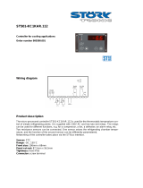
8. ESQUEMA DE LIGAÇÃO
REFR
DEFR
FANS
4
5
6
7
8
9
10
11
12
321 21
Entrada
digital
Sensor 3 ***
*** As per function F31 – Mode of Operation of Temperature sensor S3, Sensor 3 may operate as follows:
Ambient Sensor (return/ outlet air), evaporator 2 sensor or condenser sensor.
This sensor is sold separately.
7 - 8
90 - 250Vac
TC-920Ri
5.6 - Minimum and maximum temperatures register
5.7 - Enable and disable the controlling functions.
Press , soon appears and the minimum and maximum temperatures of S1 sensor (room
temperature). After soon appears and the minimum and maximum temperatures of S2 sensor
(evaporator). If the sensor S3 is enabled will appear in the sequence and the minimum and
maximum temperatures registered by this sensor.
To reset the registers keep pressed the key during the visualization of the minimum and
maximum temperatures until to be showed.
The user may disable the controlling functions of the equipment by pressing the button for 10
seconds until appears on the display. With the controlling functions being disabled, the
will only show the temperature on S1 and alternately. If you want to reactivate the
controlling functions, you only need to press the button for 10 seconds until appears on the
display.
Note:
TC-920Ri
6 - INDICATORS AND ALARMS
The leds indicate the control outputs status:
: Compressor or solenoid of liquid gas;
: Evaporator fans;
: Defrost (heating);
Internal buzzer activated;
The outputs were shut down due to the action of the digital input, see function 24;
Room sensor S1(inflating / inlet air) disconnected or out of range;
Evaporator sensor S2 disconnected or out of range;
ensor S3 (return / outlet air, 2nd evaporator or condenser) disconnected or out of range;
R sensor high temperature alarm;
R sensor low temperature alarm;
Warning 1 of high temperature in the condenser **;
Warning 2 of high temperature in the condenser (turn off the control outputs)**;
;
-
-
-
-
REFR
FANS
DEFR
BUZZ:
S
oom
oom
Alert of open door
Always that defrost ends for time and not for temperaure, a point located in the right down side of
display will blink until the next defrost indicating that:
The interval between defrosts is too high;
There are burned resistances;
The hot gas is not circulating.
There is an inoperative fan or the adjusted time is too short for the maximum duration of defrost.
SET
SET
I
** Only if the value set in the operation mode of temperature sensor S3 is equal to 2.
nvalid configuration parameters
- In this situation the outputs are turned off.
- Check which parameters have invalid data and correct them to return to normal operation.
5.3 - Process stage, elapsed tim, sensors S2 and S3 temperature
and differential S3-S1
Press . The stage of the process will appear, the elapsed time (in minutes), the evaporator
temperature (S2), sensor S3 temperature and the differential S3-S1.
Process stages: Initial delay (delay to start the control)
Fan-delay (delay to fan return)
Refrigeration
Defrost
Draining
FAN-DELAY
REFRIGERATION
DEFROST
DRAINING
Indication released
F21 F15 F19F10
Indication locked (if enabled in F18)
5.4 - Manual defrost
5.5 - How to determine the end defrost by temperature
To do a manual defrost, regardless of the programming, keep pressed for 4 seconds, until appears the
indication .
If the instrument is in defrost and you want to finish it, follow the above instructions, until appears the
indication .
Adjust the follow functions with maximum values:
- Refrigeration time (F09 = 999 min)
- Evaporator temperature for end defrost (F14 = 75 ºC)
- Maximum duration of defrost (F15 = 90 min)
Waituntil an ice layer to be created on the evaporator
Do a manual defrost, pressing for 4 seconds, until appear .
Observe the melting process.
Wait until melt allice layer on the evaporatorto consider the defrost finished.
Check the evaporator temperature readby the sensor S2 at thismoment, pressing the key (see item 5.3)
andcopy this value to the function F14 - Evaporatortemperature (S2 / S3*) for enddefrost.
As security, adjust again the function F15 - that depends of the defrost type.
Now adjust the function F09 -
a)
b)
c)
d)
e)
f)
g)
h)
Maximum duration of defrost,
Exemple: Electrical defrost (resistance) =45 minutes as maximum
Defrost for by hot gas = 20 minutes as maximum
Refrigeration time with the desired value.
7 - UNIT SELECTION (ºC / ºF)
To determine the unit that the instrument will work, access the function “F01” with the access cod 231 and
confirm with the key . Press the key . willappear.Press than use or to choose
between or and confirm with .After select the unit will appear and the instrument
returns to the function “F01”. Every time that the unit is changed, the parameters must be configurated again,
because they assume the standard values
SET
SET
SET
Sensor 1
(inflating / inlet air)
Sensor 2
(evaporator)
IMPORTANT
1:
2:
3:
According to the chapters from the IEC60364 standard:
Install on power supply
Sensor cables and computer signals can be together, however not at the same place where power
supply and load wires pass for
Install suppresor of transient in parallel to loads to increase the usefull life of the relays
protectors against over voltage
Over the specifield current
use a contactor.
Power
supply
Dimension of the clipping
for setting of the instrument
in panel
COMMON
Contact suppresor connection diagram
Suppresor
A1
A2
A1 e A2 are the
contactor coils.
Diagram for suppresor installation
for direct drive load inputs
Load
Suppresor
For direct activation the maximum
specified current should be taken
into consideration.
Note: The sensor cable lenght can be increased by the user until 200 meters using PP 2 x 24 AWG cable.
PROTECTIVE VINYL:
This adhesive vinyl (included inside the packing) protects the instruments against
water drippings, as in commercial refrigerators, for example. Do the application after
finishing the electrical connections.
Remove the protective paper
and apply the vinyl on the entire
superior part of the device,
folding the flaps as indicated by
the arrows.
ENVIRONMENTAL INFORMATION
Package:
Products:
Disposal:
The packages material are 100% recyclable. Just dispose it through specialized
recyclers.
The electro components of Full Gauge controllers can be recycled or reused if it is
disassembled for specialized companies.
Do not burn or throw in domestic garbage the controllers which have reached the end-of-
life. Observe the respectively law in your region concerning the environmental
responsible manner of dispose its devices. In case of any doubts, contact Full Gauge
controls for assistance.
/