Page is loading ...

Installation, Use & Care Manual
This manual is updated as new information and models are released.
Visit our website for the latest manual. www.manitowocfsg.com
Leader in Ice & Beverage Dispensers
CEV SERIES
Beverage Dispensers
Part Number 020004000 10/13

We reserve the right to make product improvements at any time.
Specifications and design are subject to change without notice.
Safety Notices
As you work on Manitowoc equipment, be sure to pay
close attention to the safety notices in this manual.
Disregarding the notices may lead to serious injury and/
or damage to the equipment.
Throughout this manual, you will see the following types
of safety notices:
Procedural Notices
As you work on Manitowoc equipment, be sure to read
the procedural notices in this manual. These notices
supply helpful information which may assist you as you
work.
Throughout this manual, you will see the following types
of procedural notices:
NOTE: Text set off as a Note provides you with simple,
but useful, extra information about the procedure you
are performing.
Read These Before Proceeding:
NOTE: SAVE THESE INSTRUCTIONS.
! Warning
Text in a Warning box alerts you to a potential
personal injury situation. Be sure to read the
Warning statement before proceeding, and work
carefully.
!
Caution
Text in a Caution box alerts you to a situation in
which you could damage the equipment. Be sure to
read the Caution statement before proceeding, and
work carefully.
Important
Text in an Important box provides you with
information that may help you perform a procedure
more efficiently. Disregarding this information will
not cause damage or injury, but it may slow you
down as you work.
!
Caution
Proper installation, care and maintenance are
essential for maximum performance and trouble-
free operation of your Manitowoc equipment. Read
and understand this manual. It contains valuable
care and maintenance information. If you encounter
problems not covered by this manual, do not
proceed, contact Manitowoc Foodservice Group.
We will be happy to provide assistance.
Important
Routine adjustments and maintenance procedures
outlined in this manual are not covered by the
warranty.
! Warning
PERSONAL INJURY POTENTIAL
Do not operate equipment that has been misused,
abused, neglected, damaged, or altered/modified
from that of original manufactured specifications.

Table of Contents (continued)
Part Number 020004000 10/13
i
Section 1
General Information
Read This Manual. . . . . . . . . . . . . . . . . . . . . . . . . . . . . . . . . . . . . . . . . . . . . . . . . 1-1
Unit Inspection . . . . . . . . . . . . . . . . . . . . . . . . . . . . . . . . . . . . . . . . . . . . . . . . . . . 1-1
Model Numbers. . . . . . . . . . . . . . . . . . . . . . . . . . . . . . . . . . . . . . . . . . . . . . . . . . . 1-1
Serial Number Location . . . . . . . . . . . . . . . . . . . . . . . . . . . . . . . . . . . . . . . . . . . . 1-2
Warranty Information . . . . . . . . . . . . . . . . . . . . . . . . . . . . . . . . . . . . . . . . . . . . . . 1-2
Section 2MBS
Installation Instructions
General System Overview . . . . . . . . . . . . . . . . . . . . . . . . . . . . . . . . . . . . . . . . . . 2-1
Pre-installation Checklist. . . . . . . . . . . . . . . . . . . . . . . . . . . . . . . . . . . . . . . . . . . 2-2
Selecting Locations . . . . . . . . . . . . . . . . . . . . . . . . . . . . . . . . . . . . . . . . . . . . . . . 2-4
Placing Unit in the Operating Position . . . . . . . . . . . . . . . . . . . . . . . . . . . . 2-4
Footprints . . . . . . . . . . . . . . . . . . . . . . . . . . . . . . . . . . . . . . . . . . . . . . . . . . . . . . . 2-6
CEV30 Footprint . . . . . . . . . . . . . . . . . . . . . . . . . . . . . . . . . . . . . . . . . . . . . 2-6
CEV40 Footprint . . . . . . . . . . . . . . . . . . . . . . . . . . . . . . . . . . . . . . . . . . . . . 2-7
Location. . . . . . . . . . . . . . . . . . . . . . . . . . . . . . . . . . . . . . . . . . . . . . . . . . . . . . . . . 2-8
Electrical . . . . . . . . . . . . . . . . . . . . . . . . . . . . . . . . . . . . . . . . . . . . . . . . . . . . . . . . 2-9
General . . . . . . . . . . . . . . . . . . . . . . . . . . . . . . . . . . . . . . . . . . . . . . . . . . . . 2-9
Minimum Circuit Ampacity . . . . . . . . . . . . . . . . . . . . . . . . . . . . . . . . . . . . . 2-9
Electrical Requirements . . . . . . . . . . . . . . . . . . . . . . . . . . . . . . . . . . . . . . . 2-9
Voltage . . . . . . . . . . . . . . . . . . . . . . . . . . . . . . . . . . . . . . . . . . . . . . . . . . . . 2-9
Minimum Circuit Amperage Chart . . . . . . . . . . . . . . . . . . . . . . . . . . . . . . . . 2-9
Refrigerant . . . . . . . . . . . . . . . . . . . . . . . . . . . . . . . . . . . . . . . . . . . . . . . . . 2-9
Grounding Instructions . . . . . . . . . . . . . . . . . . . . . . . . . . . . . . . . . . . . . . . . . . . . 2-9
Unit Installation. . . . . . . . . . . . . . . . . . . . . . . . . . . . . . . . . . . . . . . . . . . . . . . . . . . 2-11
Counter Sealing . . . . . . . . . . . . . . . . . . . . . . . . . . . . . . . . . . . . . . . . . . . . . 2-11
Filling the water tank . . . . . . . . . . . . . . . . . . . . . . . . . . . . . . . . . . . . . . . . . . 2-11
Refrigeration System Start . . . . . . . . . . . . . . . . . . . . . . . . . . . . . . . . . . . . . 2-12
Incoming Water Supply requirements . . . . . . . . . . . . . . . . . . . . . . . . . . . . . 2-12
Connecting the Drain Pan Hose . . . . . . . . . . . . . . . . . . . . . . . . . . . . . . . . . 2-12
Carbonator Tank Purge Tube Routing . . . . . . . . . . . . . . . . . . . . . . . . . . . . 2-13
Connecting Water & Syrup Supply Line(s) . . . . . . . . . . . . . . . . . . . . . . . . . 2-14
Premix Pressures . . . . . . . . . . . . . . . . . . . . . . . . . . . . . . . . . . . . . . . . . . . . 2-14
Plumbing Diagrams . . . . . . . . . . . . . . . . . . . . . . . . . . . . . . . . . . . . . . . . . . . 2-15
Carbonated/non-carbonated Conversion Instructions . . . . . . . . . . . . . . . . 2-17
CEV Bag-in-Box (BIB) Start-up . . . . . . . . . . . . . . . . . . . . . . . . . . . . . . . . . . 2-17
Install Labels . . . . . . . . . . . . . . . . . . . . . . . . . . . . . . . . . . . . . . . . . . . . . . . . 2-17
ADA Key Pads . . . . . . . . . . . . . . . . . . . . . . . . . . . . . . . . . . . . . . . . . . . . . . 2-18

Table of Contents (continued)
ii Part Number 020004000 10/13
Section 3
Operation
Component Identification. . . . . . . . . . . . . . . . . . . . . . . . . . . . . . . . . . . . . . . . . . . 3-1
Sequence of Operation. . . . . . . . . . . . . . . . . . . . . . . . . . . . . . . . . . . . . . . . . . . . . 3-1
Unit Inspection . . . . . . . . . . . . . . . . . . . . . . . . . . . . . . . . . . . . . . . . . . . . . . . 3-1
Beverage Valves . . . . . . . . . . . . . . . . . . . . . . . . . . . . . . . . . . . . . . . . . . . . . 3-2
Carbonated Water . . . . . . . . . . . . . . . . . . . . . . . . . . . . . . . . . . . . . . . . . . . . 3-3
Syrup Delivery System . . . . . . . . . . . . . . . . . . . . . . . . . . . . . . . . . . . . . . . . 3-3
Back Room Package . . . . . . . . . . . . . . . . . . . . . . . . . . . . . . . . . . . . . . . . . . 3-3
Figal System . . . . . . . . . . . . . . . . . . . . . . . . . . . . . . . . . . . . . . . . . . . . . . . . 3-4
Figal Tanks . . . . . . . . . . . . . . . . . . . . . . . . . . . . . . . . . . . . . . . . . . . . . . . . . 3-4
Racking . . . . . . . . . . . . . . . . . . . . . . . . . . . . . . . . . . . . . . . . . . . . . . . . . . . . 3-4
B-I-B . . . . . . . . . . . . . . . . . . . . . . . . . . . . . . . . . . . . . . . . . . . . . . . . . . . . . . 3-4
Pumps . . . . . . . . . . . . . . . . . . . . . . . . . . . . . . . . . . . . . . . . . . . . . . . . . . . . . 3-4
Auto Bag Selectors . . . . . . . . . . . . . . . . . . . . . . . . . . . . . . . . . . . . . . . . . . . 3-4
Operation Checks and Adjustments . . . . . . . . . . . . . . . . . . . . . . . . . . . . . . . . . . 3-5
Electronic Ice and & Carbonation Control . . . . . . . . . . . . . . . . . . . . . . . . . . 3-5
Section 4
Maintenance
Cleaning. . . . . . . . . . . . . . . . . . . . . . . . . . . . . . . . . . . . . . . . . . . . . . . . . . . . . . . . . 4-1
Daily Cleaning . . . . . . . . . . . . . . . . . . . . . . . . . . . . . . . . . . . . . . . . . . . . . . . 4-1
Water Bath . . . . . . . . . . . . . . . . . . . . . . . . . . . . . . . . . . . . . . . . . . . . . . . . . . 4-1
Cleaning Checklist . . . . . . . . . . . . . . . . . . . . . . . . . . . . . . . . . . . . . . . . . . . . 4-2
Preventive Maintenance . . . . . . . . . . . . . . . . . . . . . . . . . . . . . . . . . . . . . . . 4-2
Sanitizing . . . . . . . . . . . . . . . . . . . . . . . . . . . . . . . . . . . . . . . . . . . . . . . . . . . . . . . . 4-2
Beverage System Cleaning . . . . . . . . . . . . . . . . . . . . . . . . . . . . . . . . . . . . . 4-2
Shipping, Storage and Relocation. . . . . . . . . . . . . . . . . . . . . . . . . . . . . . . . . . . . 4-4
Section 5
Before Calling for Service
Checklist . . . . . . . . . . . . . . . . . . . . . . . . . . . . . . . . . . . . . . . . . . . . . . . . . . . . . . . . 5-1
Drink Troubleshooting . . . . . . . . . . . . . . . . . . . . . . . . . . . . . . . . . . . . . . . . . 5-1
Pump Troubleshooting. . . . . . . . . . . . . . . . . . . . . . . . . . . . . . . . . . . . . . . . . . . . . 5-2

Part Number 020004000 10/13 1-1
Section 1
General Information
Read This Manual
Manitowoc Beverage Systems (MBS) developed this
manual as a reference guide for the owner/operator and
installer of this equipment. Please read this manual
before installation or operation of the machine. A
qualified service technician must perform installation and
start-up of this equipment, consult Section 5 within this
manual for service assistance.
If you cannot correct the service problem, call your MBS
Service Agent or Distributor. Always have your model
and serial number available when you call.
Your Service Agent ____________________________
Service Agent Telephone Number_________________
Your Local MBE Distributor ______________________
Distributor Telephone Number____________________
Model Number _______________________________
Serial Number ________________________________
Installation Date ______________________________
Unit Inspection
Thoroughly inspect the unit upon delivery. Immediately
report any damage that occurred during transportation to
the delivery carrier. Request a written inspection report
from a claims inspector to document any necessary
claim.
Model Numbers
This manual covers the following models:
!
Warning
PERSONAL INJURY POTENTIAL
Do not operate equipment that has been misused,
abused, neglected, damaged, or altered/modified
from that of original manufactured specifications.
Beverage Dispensers
CEVe-30, CEVe-40, CEVi-30, CEVi-40, CEVj-30

General Information Section 1
1-2
Part Number 020004000 10/13
Serial Number Location
This number is required when requesting information
from your local distributor. The serial number is listed on
the SERIAL NUMBER DECAL affixed to the dispenser.
Serial Number Location
Warranty Information
Consult your local MBS Distributor for terms and
conditions of your warranty. Your warranty specifically
excludes all beverage valve brixing, general
adjustments, cleaning, accessories and related
servicing.
Your warranty card must be returned to MBS to activate
the warranty on this equipment. If a warranty card is not
returned, the warranty period can begin when the
equipment leaves the MBS factory.
No equipment may be returned to MBS without a written
Return Materials Authorization (RMA). Equipment
returned without an RMA will be refused at MBS’s dock
and returned to the sender at the sender’s expense.
Please contact your local MBS distributor for return
procedures.
Label

Part Number 020004000 10/13 2-1
Section 2
Installation Instructions
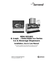
General System Overview
These instructions are provided to assist the qualified
installer. Contact your Manitowoc Beverage Equipment
Service Agent or call Manitowoc Beverage Equipment
for information regarding start-up services.
Typical CEV Series Internal Carbonation Beverage Dispensing System
Typical CEV External Carbonation (Ambient) Beverage Dispensing System
Important
Failure to follow these installation guidelines may
affect warranty coverage.
TO THE CARB TANK
90-
1800
60
100
CO
2
CO
2
CARBONATED WATER
NON-CARBONATED WATER
SYRUP
SYRUP
Carbonator
Tank
CO
2
Cylinder
Tap Water
Tap Water
Bag-In-Box
Syrup
Carton
BIB
Syrup Pump

Installation Instructions Section 2
2-2
Part Number 020004000 10/13
Pre-installation Checklist
When installing any system, first make sure the major components are available. Generally the major components
necessary for an installation are:
Pre-mix System:
B-I-B System also:
Post Mix System:
Figal system also:
CO
2
regulator set
Product connectors for Figal tank
Gas connectors for Figal tank
Beverage dispenser
Beverage tubing
CO
2
tank
Figal beverage tanks
Stepless (Oetiker) clamps
Chain for CO
2
tank
B-I-B connectors
B-I-B regulator set
B-I-B rack
B-I-B syrup boxes
CO
2
regulator set
Beverage dispenser
Beverage tubing
CO
2
tank
Carbonator
Stepless (Oetiker) clamps
Chain for CO
2
tank
Syrup connectors for Figal tank
Gas connectors for Figal tank
Figal syrup tanks

Section 2 Installation Instructions
Part Number 020004000 10/13 2-3
Bulk Syrup System also:
Double Check:
Also consider the location of the following items
before installation:
Syrup connectors for Bulk tank
Gas connectors for Bulk tank
Bulk syrup tanks
Do you have enough space to install the
dispenser or a dispenser and top mounted
cuber?
Does top mounted cuber (if utilized) have a
minimum of 6 inches (15.3 cm) clearance on all
sides?
Is the countertop level?
Can the countertop support the weight of the
dispenser, or the dispenser/cuber combination
plus the weight of the stored ice?
Water line
Drain
Power outlet
Heating and air conditioning ducts

Installation Instructions Section 2
2-4
Part Number 020004000 10/13
Selecting Locations
The CEV may be island-mounted or installed on a front
or rear counter. Locate the CEV so the following
requirements are satisfied: CEV is for indoor use only
and must NOT be placed in an area where a water jet or
similar high pressure sprayer could be used.
1. CEV must be installed near a properly grounded
electrical outlet with proper electrical requirements
fused at proper amperage or circuit connected
through an equivalent HACR circuit breaker with
ELCB (GFCI). REFER TO UNIT NAMEPLATE FOR
THE REQUIRED POWER CIRCUIT OPERATING
VOLTAGE. HERTZ AND THE MINIMUM CIRCUIT
AMPACITY OF THE CEV. No other electrical
equipment should be connected to this circuit. ALL
ELECTRICAL WIRING MUST CONFORM TO
NATIONAL AND LOCAL ELECTRICAL CODES.
MAIN PLUG MUST BE ACCESSIBLE FOR
DISCONNECTION.
2. A minimum of 15-inches clearance must be
maintained above the CEV to the nearest
obstruction (shelf, cupboard, ceiling, etc.) and 4-
inches clearance between the back of the CEV and
the wall and 12-inches between each side and the
wall. CEV has a top air outlet and is to remain free of
all objects. Do not place anything on top of the CEV.
The rear grill of the CEV must be unobstructed to
allow air to enter the hood. This will also allow
access to the condenser filter for cleaning.
3. If a permanent drain is to be used place CEV close
to a permanent drain in order to route the drain pan
hose to the permanent drain. Water tank overflow
hose goes into the drain pan.
PLACING UNIT IN THE OPERATING POSITION
The CEV must be level horizontally from right to left and
front to rear. CEV inlet supply lines, power cord, and
drain pan hose must either be routed out of the CEV
base rear access hole, or through a hole cut in the
countertop under the CEV Unit. Proceed to applicable
installation procedure. Two plastic tubing brackets are
mounted under the CEV to hold the lines in place. The
rear access cover may be removed, turned and installed
to provide a brace to prevent the CEV from being
pushed flat against the wall.Dimensions
Island Mount
Place the CEV in location on the countertop flush with
the countertop edge. Mark CEV’s center line on the edge
of the countertop, then move the CEV to one side.
Starting at the center line mark on the edge of the
countertop, measure back 12-inches for the location of a
hole at least 4-inches to be cut into the countertop. Cut
at least a 4 inch hole in the countertop where indicated.
Place the CEV in position over the hole. Route the inlet
supply lines, power cord, carbonator tank purge tube
and drain pan hose down through the hole in the
countertop.Install the line outlet plug, provided with the
CEV in the base back access hole. The area around the
inlet supply lines at the flanged hole behind the front
access panel must be closed and sealed.
Counter Mount
Place the CEV in location on the countertop. Route CEV
inlet supply lines, power cord, carbonator tank purge
tube and drain pan hose out of the base back access
hole. Area around inlet supply lines at flanged hole
behind front access panel must be closed and sealed.
ABOVE: How to Remove the Bonnet

Section 2 Installation Instructions
Part Number 020004000 10/13 2-5
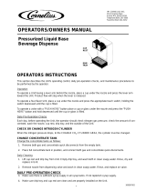
Counter Electric Dispenser Dimensions
* C = Valve height using Flomatic Valves.
MODEL A B C* D E F G H I
CEV-30 29.88"
(75.9 cm)
20.50"
(52.7 cm)
11.76"
(29.8 cm)
4.44"
(11.3 cm)
N/A N/A 25.75"
(65.4 cm)
17.00"
(43.1 cm)
17.50"
(44.4 cm)
CEV-40 29.88"
(75.9 cm)
26.00"
(66.0 cm)
11.76"
(29.8 cm)
4.44"
(11.3 cm)
N/A N/A 25.75"
(65.4 cm)
17.00"
(43.1 cm)
23.00"
(58.4 cm)
B
C
D
G
F
E
I
H
A
!
Caution
Cutting the countertop may decrease its strength.
Counter should be braced to support the dispenser
countertop weight plus ice storage capacity and
weight of icemaker, if applicable.


Installation Instructions Section 2
2-8
Part Number 020004000 10/13
Location
Avoid placing the dispenser near heat sources such as
radiators, ovens, refrigeration equipment and direct
sunlight.
!
Warning
Carbon Dioxide (CO
2
) displaces oxygen. Exposure
to a high concentration of CO
2
gas causes tremors,
which are followed rapidly by loss of consciousness
and suffocation. If a CO
2
gas leak is suspected,
particularly in a small area, immediately ventilate
the area before repairing the leak. CO
2
lines and
pumps should not be installed in an enclosed
space. An enclosed space can be a cooler or small
room or closet. This may include convenience
stores with glass door self serve coolers. If you
suspect CO
2
may build up in an area, venting of the
B-I-B pumps and / or CO
2
monitors should be
utilized.

Section 2 Installation Instructions
Part Number 020004000 10/13 2-9
Electrical
GENERAL
MINIMUM CIRCUIT AMPACITY
The minimum circuit ampacity is used to help select the
wire size of the electrical supply. (Minimum circuit
ampacity is not the beverage/ice machine’s running amp
load.) The wire size (or gauge) is also dependent upon
location, materials used, length of run, etc., so it must be
determined by a qualified electrician.
ELECTRICAL REQUIREMENTS
Refer to Machine Model/Serial Plate for voltage/
amperage specifications.
VOLTAGE
The standard voltage for CEV Series dispensers is
120VAC-60Hz 1 Ph. A power cord is provided with
120VAC-60Hz models only. 220/240 Volts - 50 Hz - 1 Ph,
208/230 Volts - 60 Hz - 1 Ph are also available.
MINIMUM CIRCUIT AMPERAGE CHART
REFRIGERANT
Optimum Ambient Conditions are between 50°F and
95°F (10°C and 35°C).
Grounding Instructions
This appliance must be grounded. In the event of
malfunction or breakdown, grounding provides a path of
least resistance for electric current to reduce the risk of
electric shock. This appliance is equipped with a cord
having an equipment-grounding conductor and a
grounding plug. The plug must be plugged into an
appropriate outlet that is properly installed and grounded
in accordance with all local codes and ordinances.
!
Warning
All wiring must conform to local, state and national codes.
Dispenser Voltage/Cycle Fuse Size
Circuit
Amps
CEV-30,
CEV-40
120/60 20 amp
8.2 Operating
amps
13 FLA
220/50, 240/50,
208/60, 230/60
10 amp 4.5 Operating
amps
7.0 FLA
Dispenser Voltage/Cycle Refrigerant Compressor
CEV-30,
CEV-40
120/60, 220/50,
240/50, 208/60,
230/60
R-134a - 8 oz
1/3 HP
Important
Due to continuous improvements, this information is
for reference only. Please refer to the dispenser
serial number tag to verify electrical data. Serial tag
information overrides information listed on this page.
!
Warning
Risk of electrical shock. Connect to a properly
grounded outlet only.
!
Warning
Improper connection of the equipment-grounding
conductor can result in a risk of electric shock. The
conductor with insulation having an outer surface
that is green with or without yellow stripes is the
equipment grounding conductor. If repair or
replacement of the cord or plug is necessary, do not
connect the equipment-grounding conductor to a
live terminal. Check with a qualified electrician or
serviceman if the grounding instructions are not
completely understood, or if in doubt as to whether
the appliance is properly grounded. Do not modify
the plug provided with the appliance — if it will not fit
the outlet, have a proper outlet installed by a
qualified electrician.

Installation Instructions Section 2
2-10
Part Number 020004000 10/13
!
Warning
When using electric appliances, basic precautions
should always be followed, including the following:
a. Read all the instructions before using the
appliance.
b. To reduce the risk of injury, close
supervision is necessary when an
appliance is used near children.
c. Do not contact moving parts.
d. Only use attachments recommended or
sold by the manufacturer.
e. Do not use outdoors.
f. For a cord-connected appliance, the
following shall be included:
• Do not unplug by pulling on cord. To
unplug, grasp the plug, not the cord.
• Unplug from outlet when not in use and
before servicing or cleaning.
• Do not operate any appliance with a
damaged cord or plug, or after the
appliance malfunctions or is dropped or
damaged in any manner. Contact the
nearest authorized service facility for
examination, repair, or electrical or
mechanical adjustment.
g. For a permanently connected appliance —
Turn the power switch to the off position
when the appliance is not in use and before
servicing or cleaning.
h. For an appliance with a replaceable lamp —
Always unplug before replacing the lamp.
Replace the bulb with the same type.
i. For a grounded appliance — Connect to a
properly grounded outlet only. See
Grounding Instructions.

Section 2 Installation Instructions
Part Number 020004000 10/13 2-11
Unit Installation
COUNTER SEALING
In order for all CEV units to comply with NSF requirements
within the United States, the CEV base must be sealed to
the countertop unless the optional 4” legs are installed. All
access holes to the base must be sealed. If the 4” legs are
installed, proceed to Filling the Water Tank, otherwise
proceed as follows to seal the CEV base:
A. Tilt CEV up to expose bottom of base.
B. Remove the 2 plastic tubes under the CEV.
C. Liberally apply silastic sealant such as Dow
Corning RTV 731 or equivalent on the base
bottom edges.
D. Lower the CEV into operating position on the
counter top to complete the seal of the base to
the countertop.
NOTE: Do not move CEV after positioning or the seal
between the base and the countertop will be broken.
E. Apply additional sealant around the bottom of
the base. The seal must be a minimum of 1/4
inch to prevent crevices and to ensure a
complete seal.
FILLING THE WATER TANK
1. Make sure the plug in the water tank drain hose is
secure.
2. Remove the plug from the water fill hole located on
the carbonator pump deck. Fill the water tank with
clean water until water flows out of the tank overflow.
Use a funnel if necessary. Caution: Be careful not to
spill water on any electrical fitting or connection. Do
not use distilled water.
NOTE: An alternative method to fill the water tank would
be to temporarily splice the incoming water line into the
water tank drain hose, turn on the water and fill the tank
until water comes out the overflow drain. Turn off the
water and plug the water tank drain hose.
3. Install plug in water fill hole.
4. Place CEV power switch, compressor switch and
the carbonator switch, located on the front of the
control box, in “OFF” position.
NOTE: Complete control box instructions may be found
in the Electronic Ice & Carbonation Control section.
!
Warning
CEV must be electrically grounded to avoid possible fatal
electrical shock or serious injury to the operator. 120V CEV
power cord is equipped with a three-prong plug. If supply
cord is damaged it must be replaced by the manufacturer or
its service agent or a similarly qualified person in order to
avoid a hazard. If a grounded electrical outlet is not
available, use an approved method to ground the CEV.

Installation Instructions Section 2
2-12
Part Number 020004000 10/13
REFRIGERATION SYSTEM START
A. Assure the water tank is properly filled. The CEV
will not operate without water in the tank.
B. Assure the voltage switch on the left side of the
control box is in the proper voltage position.
Selections are 115 Volts or 230 Volts.
C. Plug CEV power cord into an accessible,
properly grounded electrical outlet. A dedicated
circuit is strongly preferred to assure sufficient
starting and operating voltage is available to the
unit. Complete control box instructions may be
found in the Electronic Ice & Carbonation
Control section.
D. Place CEV power switch, carbonator switch (not
used on juice units) and compressor switch to
the “ON” position. The agitator motor will start,
the transformer for the valves will be energized,
the merchandiser bulb (if equipped), power
LED, carbonator LED, and compressor LED will
be illuminated.
When a full ice bank has been formed, the compressor
and condenser fan motor will stop, but the agitator motor
will continue to operate, circulating ice bath water in the
water tank. Turn the key switch to the “ON” position to
check all beverage valves for operation.
Recommended: Beverage pour temperature should be
maintained at a constant 40° F or below for optimum
brixing value. Time required to reach the proper
temperature will be subject to water and ambient air
temperatures.
NOTE: All CEV units are equipped with a 4-5 minute
delay before the compressor and fan motor start. Be
sure to observe this time delay before expecting the
compressor or condenser fan motor to start operation.
Any interruption of power to the unit, the time delay will
need to be observed before the compressor and fan
motor will start.
INCOMING WATER SUPPLY REQUIREMENTS
NOTE: Manitowoc Beverage Equipment recommends
that a water shutoff valve and water filter be installed in
the incoming water supply line.
The incoming water source to the equipment shall be
installed with adequate backflow protection to comply
with applicable National, State, and local codes.
Water pressure should be a minimum of 45 psi (310.3
KPa) or you will starve the pump of water and damage it.
The maximum water pressure should be 55 psi (379.2
KPa) or you will affect the quality of the carbonation.
The carbonator pump should be located within 6 feet of
a 1/2 inch water source. A minimum 3/8 inch ID water
line must be used. Before connection the water source
should be flushed of approximately 5 gallons of water to
purge the system of any sediments, especially in areas
of new construction.
CONNECTING THE DRAIN PAN HOSE
NOTE: Connection of the drain pan hose to a permanent
drain is recommended. A drain pan hose routed to a
waste container is not recommended due to sanitation
problems.
1. Open the end of the drain pan nipple by cutting at
the end of the barbed area along the provided
groove.
2. Connect hose to the nipple on the drain pan.
3. Install drain pan in position on the CEV, then place
grid in the drain pan.
4. Route lower end of drain pan hose to a permanent
drain and connect according to local codes.
NOTE: If no permanent drain is available the drain pan
may be emptied manually. All CEV’s come equipped
with a drain pan that may be removed by sliding it
forward. Nothing else needs to be removed to take the
drain pan off, empty it and replace it on the CEV. If this
drain pan is hooked to a permanent drain, the drain
nipple must be opened and connected to the drain hose
as described above.

Section 2 Installation Instructions
Part Number 020004000 10/13 2-13
CARBONATOR TANK PURGE TUBE ROUTING
1. During installation of unit the carbonator tank purge
tube (A) must be properly routed to a drain. Once
the splash panel has been removed from unit
remove twist tie (B) that holds carbonator tank purge
tube.
2. Purge tube is connected to the pressure relief valve
on carbonator tank and must be routed to a drain.
Route carbonator tank purge tube (A) down front of
unit and behind drain pan. Be sure not to collapse or
kink carbonator tank purge tube during routing from
unit to drain.
3. The carbonator tank purge tube (A) can be routed
down through the counter top that unit has been
installed on or out the rear of unit. Then install
carbonator tank purge tube to a drain. Follow all
local and national plumbing codes when routing
carbonator tank purge tube to the drain.
NOTE: If there is no permanent drain, route the
carbonator purge tube into the drainpan.

Installation Instructions Section 2
2-14
Part Number 020004000 10/13
CONNECTING WATER & SYRUP SUPPLY LINE(S)
Water Lines
CEVi (Internal Carbonator)
Connect plain water supply line to the CEV at the plain water
inlet line, and the non-carbonated water inlet.
CEVe (External Carbonator)
Connect carbonated water supply line from the external
carbonator to the CEV at the carbonated water inlet line.
Connect plain water supply line to the CEV at the non-
carbonated water inlet line.
CEVj (Non-Carbonated Unit)
Connect plain water supply lines to the CEV at the plain water
inlet line.
Syrup Lines
Connect syrup supply lines to the CEV at the corresponding
syrup inlet lines. Syrup inlet line #1 will correspond with the left
hand dispensing valve. The valves are numbered in
sequence from left to right.
Connecting CO
2 Supply Line & Starting The CEVi
1. Connect CO
2 supply to the CO2 inlet at the CEV.
2. Open carbonator tank pressure relief valve. (Yellow arm
should be in the upright position).
3. Turn water supply on and fill the carbonator tank until
water can be seen coming out the pressure relief valve.
4. Close the pressure relief valve.
5. Activate a dispensing valve until a good flow of plain
water is established.
6. Check for water leaks.
7. Turn on the CO
2 bottle and adjust the regulator to 75 psi
(517.10 KPa).
8. Activate a valve until all the water has been forced out of
the system by the CO
2.
9. Check for any leaks.
10. Connect the power to the carbonator.
11. Operate the valves until the carbonator cycles several
times and there is a good flow of carbonated water from
each valve.
Connecting CO
2 Supply Line & Starting the CEVe
1. Connect CO
2 supply to the CO2 inlet on the carbonator
tank.
2. Connect carbonated water outlet line to the dispensing
system. To avoid contamination of potable liquids, do not
connect copper tubing or fittings between the discharge
fitting on the carbonator and the dispensing valve.
3. Open carbonator tank pressure relief valve. (Yellow arm
should be in the upright position).
4. Turn water supply on and fill the carbonator tank until
water can be seen coming out the pressure relief valve.
5. Close the pressure relief valve.
6. Activate a dispensing valve until a good flow of plain
water is established.
7. Check for water leaks.
8. Turn on the CO
2 bottle and adjust the regulator to 100 psi
(689.48 KPa).
9. Activate a valve until all the water has been forced out of
the system by the CO
2.
10. Check for any leaks.
11. Plug in the carbonator.
12. Operate the valves until the carbonator cycles several
times.
CEVj Non-Carbonated
1. Open plain water inlet supply line valve. Check for water
leaks, tighten any loose connections.
2. Operate each dispensing valve until the system is flushed
and water flows smoothly from each valve.
PREMIX PRESSURES
Normal premix pressure regulators should be set at 60 psi
(413.7 KPa). Diet premix pressure regulators should be set
at 40 psi (275.8 KPa). If you are experiencing high foaming,
slightly decreasing the pressures may correct the problem.
Spitting and popping usually requires slightly increasing
pressures. Premix beverage valve pressures vary by type and
manufacturer. Please consult the manufacturer of the valves
you are using for specific instructions regarding operation of
the valve.
CEVi and CEVe System Pressures
1. Incoming tap water should be at a minimum pressure of
40 psi (275.8 KPa) with carbonator pump operating and
a maximum of 55 psi (379.2 KPa) with pump stopped
(measured at inlet to pump).
2. BIB pressure gauge set for 60 psi (413.69 KPa)or
according to your line run.
3. Carbonator Pressure gauge (Use Preset Regulator):
- Cold Carbonation set for 75 psi (517.1 KPa).
- Ambient systems should be set at 90 psi (310.3 KPa)
to 105 psi (310.3 KPa).
NOTE: If incoming water pressure is under 40 psi (275.8
KPa), a water booster is recommended. If incoming water
pressure is over 55 psi (379.2 KPa), a water regulating valve
is required.
/