Page is loading ...

Manitowoc Beverage Equipment
2100 Future Drive Sellersburg, IN 47172-1868
Tel: 812.246.7000, 800.367.4233 Fax: 812.246.9922
www.manitowocbeverage.com
In accordance with our policy of continuous product development and
improvement, this information is subject to change at any time without notice.
March 23, 2007 REV 0
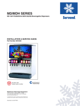
FlexTower Series
8, 12 and 16 Flavor Beverage Dispensers
INSTALLATION & SERVICE GUIDE
Part Number 020000747

FOREWORD
Manitowoc Beverage Equipment (MBE) developed this manual as a reference guide for the owner/
operator, service agent, and installer of this equipment. Please read this manual before installation
or operation of the machine. A qualified service technician should perform installation and start-
up of this equipment. Consult the
Troubleshooting Guide
within this manual for service assistance.
If you cannot correct the service problem, call your MBE Service Agent or Distributor. Always have your model and
serial number available when you call.
Your Service Agent ___________________________________________________________________
Service Agent Telephone Number ______________________________________________________
Your Local MBE Distributor ___________________________________________________________
Distributor Telephone Number _________________________________________________________
Model Number ______________________________________________________________________
Serial Number _______________________________________________________________________
Installation Date _____________________________________________________________________
UNPACKING AND INSPECTION
Note: The unit was thoroughly inspected before leaving the factory. Any damage or irregularities should
be noted at the time of delivery.
WARRANTY INFORMATION
Consult your local MBE Distributor for terms and conditions of your warranty. Your warranty specifically
excludes all beverage valve brixing, general adjustments, cleaning, accessories, and related servicing.
Your warranty card must be returned to Manitowoc Beverage Equipment to activate the warranty on this
equipment. If a warranty card is not returned, the warranty period can begin when the equipment leaves
the MBE factory.
No equipment may be returned to Manitowoc Beverage Equipment without a written Return Materials
Authorization (RMA). Equipment returned without an RMA will be refused at MBE’s dock and returned to
the sender at the sender’s expense.
Please contact your local MBE distributor for return procedures.

TABLE OF CONTENTS
FOREWORD ........................................................................................................ 2
UNPACKING AND INSPECTION......................................................................... 2
WARRANTY INFORMATION ............................................................................... 2
SAFETY ............................................................................................................... 5
IMPORTANT SAFETY INSTRUCTIONS ........................................................................... 5
CARBON DIOXIDE WARNING ......................................................................................... 5
QUALIFIED SERVICE PERSONNEL ................................................................................ 5
SHIPPING, STORAGE, AND RELOCATION ..................................................................... 5
INSTALLATION WARNING .............................................................................................. 5
ADDITIONAL WARNINGS ................................................................................................ 5
GROUNDING IN STRUCTIONS ........................................................................................ 6
INSTALLATION .................................................................................................... 7
SURVEY ........................................................................................................................... 7
COMPONENTS SHIPPED WITH FLEXTOWER ............................................................... 7
CONNECTORS................................................................................................................. 7
ESSENTIAL TOOLS ......................................................................................................... 7
FOOTPRINT ..................................................................................................................... 8
INSTALLATION PROCEDURE ......................................................................................... 9
PRECHILL COIL RETROFIT KIT & ACCESSORY MATRIX ............................................ 10
PRECHILL COIL RETROFIT KIT .....................................................................................11
RECIRCULATION LINES AND PUMP ............................................................................ 13
BRIXING PROCEDURE .................................................................................................. 16
FLEXTOWER WATER RECIRCULATION PUMP FLOW ................................................ 17
FLEXTOWER WATER CHILLER FLOW ......................................................................... 17
FT-8 PLUMBING DIAGRAM ........................................................................................... 18
FT-12 PLUMBING DIAGRAM ......................................................................................... 18
FT-16 PLUMBING DIAGRAM ......................................................................................... 19
OPERATION ...................................................................................................... 20
BASIC FUNCTIONS ....................................................................................................... 20
SPECIFICATIONS .......................................................................................................... 21
SERIAL PLATE ............................................................................................................... 21
PROGRAMMING MODES .............................................................................................. 22

TABLE OF CONTENTS
USER MAINTENANCE ...................................................................................... 25
PREVENTATIVE MAINTENANCE .................................................................................. 25
DAILY CLEANING .......................................................................................................... 25
BEVERAGE SYSTEM CLEANING ................................................................................. 27
BAG-IN-BOX SYSTEM ................................................................................................... 27
EXPLODED VIEWS, PARTS & DIAGRAMS ..................................................... 29
FT-8 WIRING DIAGRAM ................................................................................................. 29
FT-12 WIRING DIAGRAM ............................................................................................... 30
FT-16 WIRING DIAGRAM ............................................................................................... 31
POWER SUPPLY WIRING .............................................................................................. 32
POWER SUPPLY ............................................................................................................ 33
FLEXTOWER EXPLODED VIEW.................................................................................... 34
FLEXTOWER PARTS LIST ............................................................................................ 35
TROUBLESHOOTING ....................................................................................... 36
INDEX................................................................................................................. 39

5
Installation and Service Manual
WARNING: The splash panel must remain in place for installation because the splash panel pro-
vides structural integrity to the unit. Do not remove the splash panel until after the unit is installed.
SAFETY
IMPORTANT SAFETY INSTRUCTIONS
Carefully read all safety messages in this manual. Learn how to operate the FlexTower unit properly.
Do not allow anyone to operate the unit without proper training and keep it in proper working condition.
Unauthorized modifications to the FlexTower may impair function and/or safety and affect the life of
the unit.
CARBON DIOXIDE WARNING
QUALIFIED SERVICE PERSONNEL
SHIPPING, STORAGE, AND RELOCATION
INSTALLATION WARNING
ADDITIONAL WARNINGS
DANGER: Carbon Dioxide (CO
2
) displaces oxygen. Exposure to a high concentration of CO
2
gas
causes tremors, which are followed rapidly by loss of consciousness and suffocation. If a CO
2
gas leak
is suspected, particularly in a small area, immediately ventilate the area before repairing the leak. CO
2
lines and pumps should not be installed in an enclosed space. An enclosed space can be a cooler or
small room or closet. This may include convenience stores with glass door self serve coolers. If you
suspect CO
2
may build up in an area, venting of the B-I-B pumps and / or CO
2
monitors should be utilized.
WARNING: Only trained and certified electrical and plumbing technicians should service this unit.
All wiring and plumbing must conform to national and local codes.
CAUTION: Before shipping, storing, or relocating this unit, syrup systems must be sanitized. After
sanitizing, all liquids (sanitizing solution and water) must be purged from the unit. A freezing envi-
ronment causes residual sanitizing solution or water remaining inside the unit to freeze, resulting
in damage to internal components.
Installation and start-up of this equipment should be done by a qualified service technician. Operation,
maintenance, and cleaning information in this manual are provided for the user/operator of the equipment.
Save these instructions.

6
Installation and Service Manual
GROUNDING IN STRUCTIONS
SAFETY
This appliance must be grounded. In the event of malfunction or breakdown, grounding provides
a path of least resistance for electric current to reduce the risk of electric shock. This appliance is
equipped with a cord having an equipment-grounding conductor and a grounding plug. The plug
must be plugged into an appropriate outlet that is properly installed and grounded in accordance
with all local codes and ordinances.
DANGER – Improper connection of the equipment-grounding conductor can result in a risk of
electric shock. The conductor with insulation having an outer surface that is green with or without
yellow stripes is the equipment grounding conductor. If repair or replacement of the cord or plug
is necessary, do not connect the equipment-grounding conductor to a live terminal. Check with a
qualified electrician or serviceman if the grounding instructions are not completely understood, or
if in doubt as to whether the appliance is properly grounded. Do not modify the plug provided with
the appliance – if it will not fit the outlet, have a proper outlet installed by a qualified electrician.
WARNING – When using electric appliances, basic precautions should always be followed, in-
cluding the following:
a) Read all the instructions before using the appliance.
b) To reduce he risk of injury, close supervision is necessary when an appliance is used
near children.
c) Do not contact moving parts.
d) Only use attachments recommended or sold by the manufacturer.
e) Do not use outdoors.
f) For a cord-connected appliance, the following shall be included:
• Do not unplug by pulling on cord. To unplug, grasp the plug, not the cord.
• Unplug from outlet when not in use and before servicing or cleaning.
• Do not operate any appliance with a damaged cord or plug, or after the appliance
malfunctions or is dropped or damaged in any manner. Return appliance to the
nearest authorized service facility for examination, repair, or electrical or mechanical
adjustment.
g) For a permanently connected appliance – Turn the power switch to the off position
when the appliance is not in use and before servicing or cleaning.
h) For an appliance with a replaceable lamp – always unplug before replacing the lamp.
Replace the bulb with the same type.
i) For a grounded appliance – Connect to a properly grounded outlet only. See Ground-
ing Instructions.
SAVE THESE INSTRUCTIONS
WARNING
:
Risk of electrical shock. Connect to a properly grounded outlet only.

7
Installation and Service Manual
INSTALLATION
SURVEY
Prior to installation, a location survey is highly recommended to assure there is sufficient room for the FlexTower on
the counter, for the BIB rack in the back room, and room to route the beverage tubing from the BIB rack.
If an ice drink dispenser heat exchanger is used, assure that the ice drink dispenser is in close proximity to the
FlexTower area so the heat exchanger can be easily routed to the tower to provide cold water for the finished
beverages. Other methods of cooling the water are available. Contact your Manitowoc Beverage Equipment dis-
tributor for details.
Assure that a 115 Volt, 15 amp electrical outlet is available to provide power for the FlexTower and the water pump.
A separate outlet is recommended for each component
Assure that a ¾”( 2 cm) water line with a shut off valve is available in close proximity to the FlexTower. Water
treatment is highly recommended to assure a quality finished beverage. Minimum water pressure is 40 PSI (2.75
BAR) dynamic and maximum is 80 PSI (5.5 BAR) static.
COMPONENTS SHIPPED WITH FLEXTOWER
With unit:
• Water recirculation pump with power cord and
insulated tubing.
• Four (4) bolt/nut sets for securing FlexTower
to most countertops.
• Template for mounting hardware locations. This
template is part of the shipping carton. DO NOT
DISCARD CARTON UNTIL TEMPLATE HAS
BEEN REMOVED.
If location uses heat exchanger, kit consisting of:
• heat exchanger
• supplementary installation instructions
CONNECTORS
Syrup should be available on site location at the time of installation to avoid delays and costly return trips to
finish the installation. It will be necessary to determine the type of BIB connector used with the syrups. Use the
following part numbers when ordering additional kits or replacement parts.
NOTE:
The installer is responsible for compliance with all federal, state, and local laws
and regulations applying to electrical and plumbing requirements in the installation and
operation of the FlexTower and any associated accessories.
NOTE:
It may be necessary to cut the countertop to provide access for syrup and water
lines. It is recommended to route lines from below rather than from the back if possible.
P37SBBKHN (Coca Cola) QCD-II (General Bottler) PCS1 (Pepsi)
ESSENTIAL TOOLS
• Tubing Cutters
• Oetiker pliers
• Phillips and slotted screwdriver
• Power drill
• Six (6) inch adjustable wrench
• Tape Measure

8
Installation and Service Manual
INSTALLATION
FOOTPRINT
The FlexTower must be secured to the countertop using the four (4) holes provided in the base of the unit and using
the hardware provided. Follow customer guidelines for placement of the unit or approximately 10 inches (25.4 cm)
from the edge of the counter. A mounting template is provided which is printed on the shipping carton.
NOTE: DO
NOT DISCARD SHIPPING CARTON UNTIL MOUNTING TEMPLATE IS REMOVED.
Also see the Footprint below.
CAUTION:
Cutting the countertop may decrease its strength. Counter should be
braced to support the dispenser countertop weight plus ice storage capacity and
weight of icemaker, if applicable.

9
Installation and Service Manual
Cosmetic Nozzle
Splash Shield
Grid
Drain pan
Removable
Rivet
INSTALLATION
INSTALLATION PROCEDURE
• Assure that 16 bags of syrup are available at loca-
tion. Coordinate this with the store manager. Mani-
towoc Beverage Equipment does not supply syrup.
• Carefully unpack FlexTower and inspect for damage.
If damage is noted, file freight claim with carrier.
• Remove mounting template from shipping carton for
use in positioning FlexTower on counter and drilling
holes for mounting.
• Check to assure that all installation components
shipped with FlexTower are in the package.
• Check backroom components to assure that all are
with shipment.
1. Determine type of heat exchanger to be used to cool
finished beverage water and install according to in-
structions provided with heat exchanger.
2. In the back room, determine location for BIB rack
and install.
3. Route C0
2
supply to C0
2
regulator. Do not turn on
C0
2
pressure at this time.
4. Using the template provided, determine location
where the FlexTower is to be installed. Note: Flex-
Tower should be located next to the ice dispenser.
Cut out the tubing access area and drill the required
holes for the mounting hardware.
5. Remove splash shield, cosmetic nozzle, and grid
from unit. Remove the removable rivets from the
bottom left and right sides of the front cover, lift up
and pull the front cover forward and off.
6. Label and route the two (2) eight (8) line conduit
between BIB rack and area and FlexTower location.
7. Install water pump and plumb to water source and
to heat exchanger.
8. Route water lines from pump to FlexTower location.
9. Connect water lines to tee fitting supplying water
valve. (See Plumbing Diagram)
10. Connect drain. (See Drainage Options)
11. Using the FlexTower Plumbing Diagram, connect
syrup lines to syrup valves assuring that proper syrup
line is connected to the correct valve.
12. Place FlexTower in final location, apply sealant to base
of unit and secure to counter with hardware provided.
13. Place flavor labels on touch pad if required.
14. In back room, position BIB syrups on BIB rack.
15. Attach BIB connector to syrup line from syrup pump
to BIB outlet.
16. Turn on C0
2
supply and regulate to 40 PSI (2.75
BAR) for non carbonated beverages.
17. At FlexTower, purge syrup lines.
18. Turn on water supply to FlexTower and purge water line.
19. Brix valves then ensure the syrup injections
shroud assembly is firmly clipped into place and
all vinyl syrup tubes are firmly seated into their
corresponding port on the syrup injection shroud
assembly. (See Brixing Procedure)
20. Replace front cover and reinstall removable rivets, then
replace the cosmetic nozzle, splash shield and grid.
21. Install any merchandising materials shipped with
FlexTower.
22. Instruct store personnel in operation and mainte-
nance of the FlexTower and back room items.

10
Installation and Service Manual
Cooling Coil and Left Side Replacement Strip Lid Panel Kits
Ice Beverage Dispenser Model Strip Lid Kit Part Number For Kit
(See Note 1) (See Note 1)
MDH-302 IB4 020001176
MDH-302 IB5 020001176
MDH-302 SL3 020001177
MDH-302 SL4 020001178
MDH-302 SL7 020001179
MDH-302 SL11 020001180
MDH-402 SL5 020001246
MDH-402 SL6 020001247
MDH-402 SL9 020001248
MDH-402 IB6 020001249
MDH-402 IB7 020001249
MDH-402 IB8 020001250
MDH-402 IB9 020001250
MDH-402 SL8 020001251
Accessory Kits
Flex Tower Model Description Kit Part Number
FT-16, 12 and 8 Recirc Pump & Line Kit 020000783
FT-16, 12 and 8 Install Kit 020001070
BIB Racks
Flex Tower Model Description BIB Rack Part Number
FT-16 Preassembled 16 Box BIB Rack AR-6W3H16F-VERT-QCD
FT-12 Preassembled 12 Box BIB Rack AR-6W2H12F-VERT-QCD
FT-8 Preassembled 8 Box BIB Rack AR-6W2H8F-VERT-QCD
NOTES
1) When ordering cooling coil and left side replacement strip lid panel kits the following information is needed.
a) Servend ice beverage dispenser model number the cooling coil will be installed inside of.
b) The ice machine(s) model number(s) installed on top of the Servend ice beverage dispenser.
c) The information is needed in order to ship kit with the correct left side replacement strip lid panel(s) and
cooling coil.
INSTALLATION
PRECHILL COIL RETROFIT KIT & ACCESSORY MATRIX

11
Installation and Service Manual
INSTALLATION
PRECHILL COIL RETROFIT KIT
1. Disconnect or shut of power, water supply to ice
maker or makers (1A) and power supply to ice bev-
erage dispenser (1B) (See Figure 1). Failure to
do so may cause electrical shock or injury.
2. Ice beverage dispensers (1B) equipped with one
or two ice makers (1A) and a strip lid kit (2A and
2B) will need partial or total removal of items in
order to gain access to the ice storage bin for cool-
ing coil heat exchanger installation (See Figures 1
and 2).If applicable on Servend 302 and 402 ice
beverage dispensers remove ice maker (1A), strip
lid panels (2A) and support brackets (2B) from the
left side of unit only to access the left side ice stor-
age bin (See Figure 1). Keep all removed compo-
nents and ice maker or makers in a safe place for
reinstallation later.
3. Remove all ice from the ice storage bin (3A) of dis-
penser in which the cooling coil heat exchange will
be installed (See Figure 2). On Servend 302 and
402 ice beverage dispensers remove ice from left
side ice storage bin only. Remove the paddlewheel
pin or pins (3B), agitator bar (3C), double –D cou-
pling [where applicable], bin liner (3D) the four
knurled bin liner screws (3E), paddlewheel (3F),
paddlewheel area bushing [where applicable] and
paddle wheel area (3G) from ice storage bin (3A)
(See Figure 2). On Servend 302 and 402 ice bev-
erage dispensers remove the components previ-
ously listed from the left side ice storage bin only.
Keep all removed components in a safe place for
reinstallation later.
4. Part of the rubberized bin gasket (4A) will need to
be trimmed away [3.00 inches] from the back left
side corner of the ice beverage dispenser (4B) as
shown (See Figure 3).
5. Use a 3.00 inch piece of the black adhesive foam
gasket included kit to seal for sanitation reasons
over the previously trimmed 3.00 inch area (4C).
Remove protective covering from black adhesive
foam gasket before adhering to surfaces of ice
beverage dispenser (See Figure 3).
6. Clean the left inside corner of ice storage bin (4D)
from top to bottom and 6.00 inches to the left and
right with isopropyl alcohol or cleaning solution (See
Figure 3).
1A
1B
1A
2A
2B
FIGURE 1
FIGURE 2
3.00
inches
4A
4B
4C
4D
FIGURE 3
3D
3F
3G
3C
3B
3A
3E 3E
3E 3E

12
Installation and Service Manual
INSTALLATION
PRECHILL COIL RETROFIT KIT
7. Place the cooling coil heat exchanger (5A) into the
previously cleared and cleaned ice storage bin (5B)
as shown (See Figure 4). Be sure the coil is rest-
ing flat on coldplate (5C) of the ice beverage dis-
penser (See Figure 5). The inlet and outlet fittings
(8E) of the cooling coil heat exchanger will exit over
previously trimmed 3.00 inch open area (4C) of the
rubberized bin gasket (4A) in the back left corner
of the ice beverage dispenser (4B) (See Figures
3 and 6). The inlet and outlet fittings (8E) of coil
should be visible from the back of the ice beverage
dispenser (8C) (See Figure 6).
8. Remove protective covering from adhesive tape on
back of the plastic cover (6A) that is factory installed
on the cooling coil heat exchanger (6B) (See Fig-
ure 6). Place plastic cover (6A) snuggly into previ-
ously cleaned left inside corner of ice beverage dis-
penser (8C) flush with the top of the ice storage
bin (8D) as shown (See Figures 4 and 6).
9. Reinstall the paddle wheel area (3G), paddlewheel
area bushing [where applicable] and paddlewheel
(3F) in the ice storage bin (3A) that components
were previously removed from (See Figure 2).
10. Install the plastic cover support bracket (7A) under
the left side of the bin liner (7B) when reinstalling
the bin liner (7B) and the four knurled bin liner
screws (3E) as shown (See Figures 2 and 5).
11. Reinstall the double –D coupling [where appli-
cable], agitator bar (7C) and paddlewheel pin or pins
(7D) in the ice storage bin (7E) that components
were previously removed from (See Figure 5).
12. If applicable reinstall strip lid kit or components pre-
viously removed for access to install cooling coil
heat exchanger in the ice beverage dispenser. The
original left side strip lid panel (2A) and support
brace
(2B) [where applicable] will be replaced by
a new left side strip lid panel and support brace
included with some but not all kits (See Figure 1).
13. Reinstall the ice maker or makers (1A) using the
proper install procedures on the ice beverage dis-
penser (1B) (See Figure 1).
14. Place label (8A) [Part No.5011948] near existing
serial tag (8B) of ice beverage dispenser (8C) (See
Figure 6).
15. Reconnect or turn on the water, power supplies to
the ice beverage dispenser and ice maker or mak-
ers. Check for leaks and make sure the ice bev-
erage dispenser, ice maker or makers operate
normally before placing units back into general
service.
8A
8B
8C
8D
8E
FIGURE 6
FIGURE 5
FIGURE 4
6A
5A 5C
5B
7A
7B
7C
7D
7E

13
Installation and Service Manual
INSTALLATION
RECIRCULATION LINES AND PUMP
1A
1C
1D
1B
1F
1G
1E
FIGURE 1
1. If required secure recirculation pump (1A) to counter
or under counter that unit is installed on (See Figure
1). Run insulated beverage line (1B) from the barded
pump outlet fitting up to the right barbed cooling coil
inlet (2A) on back of dispenser and secure both ends
of line to the barbed fittings with otiker clamps (See
Figures 1 and 2). Connect another insulated bever-
age line to left barbed cooling coil outlet (2B) on back
of dispenser and secure line to barbed fitting with otiker
clamp (See Figure 2).
2. Wrap cork tape insulation around the barbed inlets
(3A) and insulated beverage lines (3B) as shown (See
Figure 3
). Installation of cork tape must be done
properly to prevent condensation and tempera-
ture gain of circulating water.
3. Route insulated beverage line from the cooling coil
outlet (2B) up through either the back or bottom of
tower (4A) as shown (See Figures 2 and 4). Route
insulated beverage line through left side hole in the
valve mount plate (4B) as shown (See Figure 4).
Connect insulated beverage line to left side of barb
fitting (4C) and secure line to barbed fitting with otiker
clamp (See Figure 4). Connect the last insulated
beverage line to right side of barbed fitting (4E) and
secure line to barbed fitting with otiker clamp (See
Figure 4). Wrap fitting and insulated beverage lines
(4D) with cork tape insulation (See Figure 4).
Instal-
lation of cork tape must be done properly to pre-
vent condensation and temperature gain of
cir-
culating water
.
4. Chiller Installations: When using a refrigerated
chiller (5A) for cooling plain water supplied to tower
the recirculation pump can be mounted to the exte-
rior cabinet of chiller (See Figure 5)..
5. Chiller Installations: Attach insulated beverage line
(1B) to the pump outlet fitting and secure with otiker
clamp. Then run insulated line (1B) to the plain water
coil inlet (5B) of the chiller (5A). Secure line to the coil
inlet (5B) of the chiller (5A) mechanically. If applicable
us an otiker clamp (See Figures 1 and 5).
6. Chiller Installations: Connect another insulated bev-
erage line to the plain water coil outlet (5C) of the
chiller (5A). Secure line to the coil outlet (5C) of the
chiller (5A) mechanically. If applicable us an otiker
clamp (See Figure 5).
FIGURE 2
FIGURE 3
2A
2B
3A
3B
PARTS INCLUDED IN KIT NO: 020000783
Qty. Description Part Number
1 Recirculation pump/w/fittings 020000780
3 Line insulated beverage 020000781
1 Instructions Recirculation lines 020000782
10 Clamp Otiker 15.7 15.7-706R
6ft Tape Cork Insulation RM051120

14
Installation and Service Manual
7. Chiller Installations: Route insulated beverage line
from the coil outlet (5C) up through either the back or
bottom of tower (4A) as shown (See Figures 4 and
5). Route insulated beverage line through left side
hole in the valve mount plate (4B) as shown (See
Figure 4). Connect insulated beverage line to left
side of barb fitting (4C) and secure line to barbed
fitting with otiker clamp (See Figure 4). Connect the
last insulated beverage line to right side of barbed
fitting (4E) and secure line to barbed fitting with otiker
clamp (See Figure 4). Wrap fitting and insulated bev-
erage lines (4D) with cork tape insulation (See Fig-
ure 4).
Installation of cork tape must be done prop-
erly to prevent condensation and temperature
gain of
circulating water
.
Cooling Coil and Chiller Common Instructions
8. Route insulated beverage line through right side hole
in the valve mount plate (4F) as shown (See Figure
4). Route insulated beverage line either through back
or bottom of tower (See Figure 4).
9. Connect insulated beverage line from right side of
tower to pump inlet barbed fitting (1C) and secure
with otiker clamp (See Figure 1). Connect potable
water supply line (3/8 ID line size) to barbed pump
connection (1D) and secure line with otiker clamp (See
Figure 1). After all line connections have been made
ensure potable water supply is flowing or turned on
and check for leaks. If no leaks are present dispense
water through the tower to purge any trapped air from
the recirculation loop and pump. Connect power sup-
ply cord (1E) from recirculation pump (1A) to recep-
tacle (1F) on the power supply (1G) or to a separate
power outlet or receptacle (See Figure 1).
INSTALLATION
RECIRCULATION LINES AND PUMP
FIGURE 4
4A
4B
4C
4F
4E
4D
5B
5C 5A
FIGURE 5

15
Installation and Service Manual
INSTALLATION
DRAINAGE OPTIONS
The drains for FLEXTOWER connect to the drain pan
Option One
Drainage through the bottom of the unit:
Back of unit
Openings for beverage and drain lines.
Option Two
Drainage through the back of the unit:
Flexble Tubing
Radiator Clamp
90° Elbow Fitting
Flexble Tubing
Radiator Clamp
Straight Fitting
Rear Access for
Drain Hose &
Beverage Lines

16
Installation and Service Manual
Touchpad
Selection
Areas
Water Valve
Control
Board
LED
Syrup
Injection
Shroud
Program
Button
INSTALLATION
BRIXING PROCEDURE
NOTE:
This procedure is for flavors requiring 5:1 water to syrup ratio.
CC OZ
OZ C C
45
40
35
30
25
20
15
10
5
1
11: 1
5:1
225
8
7
6
5
5:1
RATIO
RATIO
4
3
2
1
4.75
11: 1
200
175
150
125
100
75
50
50
Funnel and 5:1 Brix Cup
1. Connect water and syrup to system and purge lines
at both the syrup and water valves to assure that syrup
and water are available at the valves.
2. If the front panel is on the front of the unit, remove it to
gain access to the syrup and water valves. In order
to remove the front panel, the grid, splash shield, and
cosmetic nozzle must be removed first.
3. Use a standard brix cup with a 5:1 ratio for the
procedure.
4. Locate the control board.
5. Press the program button until 1 is displayed on the
control board LED display.
See the Control Board Pro-
gramming pages
.
6. Press the program button until the LED displays 3.
This is the water adjustment mode on the circuit board.
7. Place the brix cup with the water side of the cup un-
der the nozzle of the water valve (located in the cen-
ter of the unit.
8. Press any touchpad selection area and the valve will
dispense water for 3 seconds.
9. Check the output volume of water. The correct vol-
ume should be 6 oz. If adjustment is needed to attain
this volume, adjust the water side adjustment screw
on the water valve until 6 oz. (177 ml) is present.
10. Repeat the above steps until the water valve is brixed
and dispensing 6 oz. (177 ml) of water in 3 seconds.
11. Press the program button on the control board until
the LED displays 4.
12. Note that each flavor has a corresponding port on
the syrup injection shroud.
13. Use the funnel provided with the FT unit to direct the
syrup into the brix cup. Place the funnel under the
syrup injection shroud and the outlet of the funnel
into the syrup side of the brix cup.
14. Press any touchpad area and the corresponding
syrup will be dispensed for 3 seconds.
15. Syrup should be even with the 6 oz. (177 ml) water
mark on the cup or at the 35cc mark on the syrup
side of the brix cup.
16. Check each syrup position and adjust syrup on the
corresponding valve as necessary. A plumbing label
is located on the unit showing the position of each
valve and syrup port.
See the Plumbing Diagram page
.
17. Return the control board to the dispense position by
pressing the program button for 3 seconds or until
the LED displays 0.
18. Check each flavor to assure that both syrup and wa-
ter are dispensing properly and that the flavor that
corresponds to the flavor label is being dispensed.
19. Replace front panel, cosmetic nozzle, splash shield,
and grid.

17
Installation and Service Manual
INSTALLATION
FLEXTOWER WATER RECIRCULATION PUMP FLOW
Plumbing and Wiring Diagrams can be located inside the front cover of the FlexTower.
FLEXTOWER WATER CHILLER FLOW

18
Installation and Service Manual
INSTALLATION
FT-8 PLUMBING DIAGRAM
FT-12 PLUMBING DIAGRAM
Plumbing and Wiring Diagrams can be located inside the front cover of the FlexTower.

19
Installation and Service Manual
Plumbing and Wiring Diagrams can be located inside the front cover of the FlexTower.
INSTALLATION
FT-16 PLUMBING DIAGRAM

20
Installation and Service Manual
OPERATION
BASIC FUNCTIONS
The FlexTower is a free standing unit which is designed for counter top merchandising and dispensing of non
carbonated finished beverages and flavoring syrups in any combination up to 16 flavors. Dispensing is accom-
plished by supplying syrup to an electric valve via a BIB pump and routing the syrup to a common dispense point
at an electric valve centrally located to supply plain water. Plain water for the non carbonated beverages is cooled
by circulation through a cooling coil placed in an adjacent ice dispenser bin and pumped by a circulation pump
located under the counter or by remote cooling units.
1. Pressing a labeled finished beverage selection
area on the touch pad activates the electric syrup
valve to deliver syrup and the water valve to pro-
vide water for the desired finished beverage.
2. Pressing a labeled flavor enhancer syrup only se-
lection area on the touch pad activates the elec-
tric valve to provide the desired flavored syrup in
a predetermined quantity. Water is not dispensed
with flavor enhancer only flavored syrup.
3. The touchpads can be changed from a non car-
bonated finished beverage to flavor enhancer
syrup only through programming on the control
board. The FlexTower is shipped with the
touchpads programmed in the non carbonated
beverage mode by default.
4. A dedicated 120 VAC, 15 ampere circuit is required
to provide power to the power supply's transformer
with an output of 24 VAC for the electric valves,
120 VAC, 8 ampere circuit, and to power a cold
water recirculation pump. The power supply has a
120 VAC outlet to provide power for the cold water
recirculation pump.
5. A plain water supply capable of delivering 100 GPH
(378.5 liters/hr) with a minimum dynamic water
pressure of 40 PSI (2.75 BAR) and a maximum
static water pressure of 80 PSI (5.5 BAR) is re-
quired to provide water for the non carbonated
beverages. Water treatment is highly recom-
mended to assure a quality finished beverage.
A drain pan connection is provided at the rear of the drain pan and must be routed to a drain in conform-
ance with plumbing codes. (See Drainage Options)
The back room items (ordered separately) consist of:
1. Bag-in-box rack capable of holding sixteen flavor
boxes.
2. 0 – 100 PSI (0 – 6.9 BAR) Secondary regulator. For
non carbonated beverages delivery pressure is 40
PSI (2.75 BAR). For flavor syrup only, delivery pres-
sure is 40 PSI (2.75 BAR).
3. Beverage pumps and connecting tubing.
4. Bag-in-box connectors as required by syrup
manufacturer.
5. Two (2) – eight (8) line, .250 (.635 cm) beverage
barrier tubing conduit – 100 ft. (30.5 meters).
6. Additional .250 (.635 cm) tubing for C0
2
supply.
7. Oetiker clamps and fittings.
8. 2.5 gallon (9.5 liter) bag-in-box syrup containers with
a dip tube to allow multidirectional placement on
the rack is suggested. This will allow for a 6-6-4
bag placement on the rack. This product is sup-
plied by customer or syrup manufacturer and is not
available through Manitowoc Beverage Equipment.
/