Page is loading ...

INSTALLATION GUIDE
1139 Bill Trap Transmitter
Description
The 1139 Bill Trap is a wireless transmitter designed to provide a silent alarm in retail and banking cash drawers
by trapping one bill below a stack of bills. When the trapped bill is removed, a panic alarm is sent. To reduce the
possibility of a false alarm, a delay can be programmed to provide time to replace the bill should it be accidentally
removed.
Compatibility
All DMP 1100 Series Wireless Receivers and Panels
What is Included
The 1139 Bill Trap Transmitter includes the following items:
• OneBillTrapwithDMPwirelesstransmitterinstalled
• TwoCR24503.0Vlithiumcoincellbatteries
• Velcromountingstrip
• Zonenameandnumberlabel
• Serialnumberlabel
Transmitter Serial Number
For your convenience, an additional pre‑printed serial
number label is included. Record the serial number or
place the pre‑printed serial number label on the panel
programming sheet. This number is required during
programming. As needed, use the zone name and number
labeltoidentifyaspecictransmitter.
Programming the Bill Trap in the Panel
Refer to the panel programming guide as needed. Program the device as a zone in Zone Information during panel
programming.AttheSerialNumberprompt,entertheeight-digitserialnumber.Continuetoprogramthezoneas
directed in the panel programming guide.
Note: When a receiver is installed, powered up, or the panel is reset, the supervision time for transmitters is reset.
If the receiver has been powered down for more than one hour, wireless transmitters may take up to an additional
hour to send a supervision message unless tripped, tampered, or powered up. This operation extends battery life for
transmitters. A missing message may display on the keypad until the transmitter sends a supervision message.
Application Example
Whenusingan1139BillTrap,programthezoneasaPanictypezone.XR150/XR350/XR550SeriesandXR100/
XR500SeriespanelsprovideaRetardDelaythatcanbeprogrammedonPanictypezones.InSystemOptionsset
aRetardDelaytimefrom1to250seconds.Thisprovidestimetoreplaceanaccidentallyremovedbillandavoid
a false alarm. Also, an output can be assigned to the zone with the action set to Follow. When connected to a
preprogrammedDVRandcamera,andthepaniczoneistripped,thecameracanincreasetheframespeed.
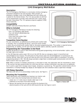
Figure 1: 1139 Bill Trap
Bill Trap Housing Base
Bill Trap Transmitter Housing
Bill Trap -
Slide one end of bill
underneath clip
to hold in place.

Digital Monitoring Products 1139 Wireless Bill Trap Installation Guide
2
Selecting the Proper Location (LED Survey Operation)
Note:RefertoFigure2toremovethe1139housingbaseandFigure3forthe1139PCBLEDandtamperswitch
locations.
The1139BillTrapprovidesasurveycapabilitytoallowonepersontoconrmtransmittercommunicationwith
thereceiverwhilethecoverisremoved.The1139BillTrapPCBRedSurveyLEDturnsonwheneverdataissent
to the receiver then immediately turns off when the
receiver acknowledgement is received. Pressing the
tamper switch is a convenient way to send data to the
receivertoconrmoperation.Whenthetamperswitch
ispressedorreleased,theLEDblinksoncetoindicate
proper operation. When the transmitter does not receive
anacknowledgementfromthereceivertheLEDremains
onforabout8secondsorashesmultipletimesin
quick succession to let you know communication is not
established. Relocate the transmitter or receiver until
theLEDimmediatelyturnsoffindicatingthetransmitter
and receiver are communicating properly. Proper
communication between the transmitter and receiver
isveriedwhenforeachpressorreleaseofthetamper
switch,theLEDblinksimmediatelyonandimmediately
off.Repeatthistesttoconrmveseparateconsecutive
LEDblinks.Anyindicationotherwisemeansproper
communication has not been established.
Installing the Bill Trap
Slide a bill into the Bill Trap on the 1139 as shown in Figure 1. The 1139 Bill Trap unit easily slides into a bill slot of a
cash drawer. Place additional bills above the trapped bill for standard cash drawer operation.
Installing or Replacing the Battery
Observepolaritywheninstallingthebattery.Useonly3.0Vlithiumbatteries,DMPModelCR2450,ortheequivalent
battery from a local retail outlet.
Note: When setting up a wireless system, it is recommended to program zones and connect the receiver before
installing batteries in the transmitters.
ToinstallorreplacebatteriesoraccessthetamperswitchandviewtheLED
ash:
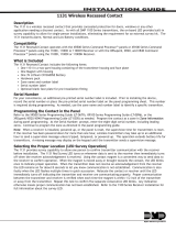
1.UseaPhillipsscrewdrivertoremovethethreescrewsholdingthebase
andhousingtogether.SeeFigure2.
2.GentlyliftthePCBoutofthehousing.
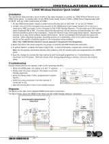
3. If installed, push and slide each old battery out of the holder in the
direction of the arrow to remove it. See Figure 3.
4.Verifythepositivesideofthenewbatteryisup.
5.Slideeachnew3.0Vlithiumbatteryintoitsholderandpushinto
place.
Lever Alarm
Switch
Universal
Antenna
CR2450 Coin Cell Batteries
with Positive Side Up
Tamper
Switch
Push the Battery
Edge to Slide
Battery Out
Red LED
Figure 3: Bill Trap Battery Locations
Bill Trap Housing
Base Mounting
Screw Locations
Figure 2: Bill Trap Base and Mounting Screw Locations

1139 Wireless Bill Trap Installation Guide Digital Monitoring Products
3
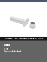
6.GentlyslidethePCBbackintothehousingmakingsuretheleveralarmswitchisinpositiontoactivate.See
Figure4.
Correct
Lever Alarm
Switch Location
Red LED
Antenna
Incorrect
Lever Alarm
Switch Location
Red LED
Antenna
Figure 4: Lever Alarm Switch Location Detail
7.UseaPhillipsscrewdrivertoreplacethebaseontothehousing.
8. Slide the bill trap back into the cash drawer.
Caution:Properlydisposeofunusedbatteries.Donotrecharge,disassemble,heatabove212°F(100°C),or
incinerate.Riskofre,explosion,andburns.
Battery Life Expectancy
Typical battery life expectancy for DMP Model 1139 Bill Trap is 1 year. DMP wireless equipment uses two‑way
communication to extend battery life.
The following situations can reduce battery life expectancy:
• Ifareceiverisunplugged,toofaraway,ornotinstalled.
Note: Transmitters continue to send supervision messages until a receiver returns an acknowledgement.
• Frequenttransmissions,suchasconstantremovingandreplacingthetrappedbill.
• Wheninstalledinextremehotorcoldenvironments.
The following situation can extend battery life expectancy:
• Extendtransmittersupervisiontimeinpanelprogramming.
• Infrequenttransmissiontrips.
FCC Information
ThisdevicecomplieswithPart15oftheFCCRules.Operationissubjecttothefollowingtwoconditions:
(1)Thisdevicemaynotcauseharmfulinterference,and
(2)thisdevicemustacceptanyinterferencereceived,includinginterferencethatmaycauseundesiredoperation.
Theantennausedforthistransmittermustbeinstalledtoprovideaseparationdistanceofatleast20cmfromall
persons.Itmustnotbeco-locatedoroperatedinconjunctionwithanyotherantennaortransmitter.
Changesormodicationsmadebytheuserandnotexpresslyapprovedbythepartyresponsibleforcompliancecould
void the user’s authority to operate the equipment.
NOTE:ThisequipmenthasbeentestedandfoundtocomplywiththelimitsforaClassBdigitaldevice,pursuant
topart15oftheFCCRules.Theselimitsaredesignedtoprovidereasonableprotectionagainstharmful
interference in a residential installation. This equipment generates, uses and can radiate radio frequency
energy and, if not installed and used in accordance with the instructions, may cause harmful interference
to radio communications. However, there is no guarantee that interference will not occur in a particular
installation. If this equipment does cause harmful interference to radio or television reception, which can be
determined by turning the equipment off and on, the user is encouraged to try to correct the interference by
one or more of the following measures:
‑ Reorient or relocate the receiving antenna.
‑ Increase the separation between the equipment and receiver.
- Connecttheequipmentintoanoutletonacircuitdifferentfromthattowhichthereceiverisconnected.
- Consultthedealeroranexperiencedradio/TVtechnicianforhelp.

LT-0693 © 2013 Digital Monitoring Products, Inc.
800-641-4282
www.dmp.com
Designed, Engineered and
Assembled in U.S.A.
INTRUSION • FIRE • ACCESS • NETWORKS
2500 North Partnership Boulevard
Springfield, Missouri 65803-8877
13215
Specications
Battery
LifeExpectancy 1yearsusing2batteries
Type 3.0VlithiumCR2450
SeeBatteryLifeExpectancyfordetails.
Transmit condition Alarm, Tamper
Dimensions
5.375”Hx2.625”Wx.625”D
Color Ivory
Housing material Flame retardant ABS
Patents
U.S.PatentNo.7,239,236
Compatibility
1100D Wireless Receiver
1100DH Wireless High Power Receiver
1100DI Wireless In‑line Receiver
1100X Wireless Receiver
1100XH Wireless High Power Receiver
XTLPanelwithintegratedwirelessreceiver
XTLCPanelwithintegratedwirelessreceiver
XTLNPanelwithintegratedwirelessreceiver
XTLN-WiFiwithintegratedwirelessreceiver
XT50Seriespanelwithintegratedwirelessreceiver
Listings and Approvals
FCCPart15RegistrationIDCCKPC0103
IndustryCanada:5251A-PC0103
/