Page is loading ...

In accordance with our policy of continuous product development and improvement,
this information is subject to change at any time without notice.
EI212147 Revision B (KAK) 3 August, 2001
Manitowoc Beverage Equipment
2100 Future Drive Sellersburg, IN 47172-1868
Tel: 812.246.7000, 800.367.4233 Fax: 812.246.9922
www.manitowocbeverage.com
Foodservice Group
Multiplex Beverage Equipment Installation Instructions for
CO2 Tank Conversion Kit
P.N. 00212147, P.N. 00212505, and P.N. 00215099
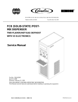
Figure 1
CO2 Caution
Label
Nylon Clamp Screw
and Washer
Tank Bracket and
Chain Assembly
1
/4 - 20 x
1
/2"
Hex Head Screw
and Nut
Introduction
The following instructions cover the installation and oper-
ating procedures of a Multiplex CO2 tank conversion kit. This
kit is designed for use with a Multiplex Model 37K and Model
44K Refrigeration Units and Stands only.
Model 37K installation
1. Locate the tank bracket and chain assembly provided with
kit.
2. Mount the tank bracket to the Model 37K unit stand with
the four (4)
1
/4-20 x
1
/2" Hex Head screws and nuts pro-
vided in kit as shown in figure 1.
Note: Since bracket is not supplied with back-up regulator
kit, the CO
2 tank(s) should be secured to the wall or stand
using eyebolt with chain supplied. Chain is on the upper third
of the CO
2 tank(s).

2
EI212147 Revision B (KAK) 3 August, 2001
Equipment Installation Instructions
Caution: To Avoid Serious Injury
Important: Read the following warnings before beginning an installation. Failure to do so
may result in possible death or serious injury.
DO Adhere to all National and Local Plumbing and Electrical Safety Codes.
DO Turn “off” incoming electrical service switches when servicing, installing, or
repairing equipment.
DO Check that all flare fittings on the carbonation tank(s) are tight. This check
should be performed with a wrench to ensure a quality seal.
DO Inspect pressure on Regulators before starting up equipment.
DO Protect eyes when working around refrigerants.
DO Use caution when handling metal surface edges of all equipment.
DO Handle CO
2 cylinders and gauges with care. Secure cylinders properly against
abrasion.
DO Store CO2 cylinder(s) in well ventilated areas.
DO NOT Throw or drop a CO2 cylinder. Secure the cylinder(s) in an upright position
with a chain.
DO NOT Connect the CO2 cylinder(s) directly to the product container. Doing so will
result in an explosion causing possible death or injury. Best to connect the
CO2 cylinder(s) to a regulator(s).
DO NOT Store CO2 cylinders in temperature above 125°F (51.7°C) near furnaces,
radiator or sources of heat.
DO NOT Release CO2 gas from old cylinder.
DO NOT Touch Refrigeration lines inside units, some may exceed temperatures of
200°F (93.3°C).
Notice: Water pipe connections and fixtures directly connected to a potable water supply
shall be sized, installed and maintained in accordance with Federal, State, and Local codes.

3
EI212147 Revision B (KAK) 3 August, 2001
Equipment Installation Instructions
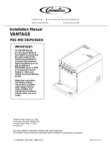
Figure 2
Figure 3
3
/8 OD Tubing
Tank Change-over
Valve Assembly
Screw, Handle, and
Retainer Ring
1
/4" MPT x
3
/8" MF Adapter
Remove and discard.
1
/4" MPT x
3
/8" OD
Compression Fitting
Primary CO2
Tank
Regulators
and Gaskets
8 ft (2.4 m)
Line Assembly
CO
2 Tanks
3. Position two (2) CO2 tanks against the edge of the tank
bracket. Secure CO
2 tanks in place with chains (refer to
figure 2).
4. Locate the two (2) primary CO
2 tank regulators labeled
“A” and “B”, and gaskets supplied with the kit. Attach a
primary CO
2 tank regulator and gasket to each CO2 tank
as shown in figure 2.
Note: If the CO
2 tanks with metric threads are supplied, the
nuts on the regulators must be changed. To replace the nuts,
remove the nipple and nut assembly from the regulator. Lo-
cate the metric nuts (supplied) and reinstall the nipple and
nut assembly. Be sure to apply the thread sealer to nipple
threads to avoid leaks.
5. Open the Model 37K Control Panel door. Remove and dis-
card the
1
/4" MPT x
3
/8" MF adaptor fitting located at the
top of the CO
2 manifold. Replace adaptor fitting with
the
1
/ 4" MP x
3
/8" OD compression fitting and compression
nut supplied in kit (refer to figure 3).
Note: When installing backup regulator kit, you must use the
1
/4" MPT x
3
/8" MF adaptor on side "B" of the tank Change-over
Valve assembly.
6. Locate the tank Change-over Valve assembly and the one
(1)
3
/8 OD piece of tubing supplied in kit. Cut tubing to
size and insert the tubing into the Change-over Valve com-
pression fitting. Do not tighten compression fitting nut at
this time (refer to figure 3).
7. Remove the screw, handle, and retainer nut or ring from
the CO
2 Change-over Valve. Install the Change-over Valve
in the control panel opening labeled CO2 Change-over Valve
tank A & B. Tighten the compression nuts at the Change-
over Valve and the CO
2 manifold. Replace retainer nut,
handle, and screw (refer to figure 3).
8. Locate the two (2) 8 ft (2.4 m) line assemblies supplied
with the kit. Attach the end of the line assembly with
swivel nut fitting to the elbow fitting of the two (2) high
pressure regulators (refer to figure 2).
9. Neatly route the opposite ends of the two (2) 8 ft line
assemblies up through the opening in the Control Panel
door. Attach the line coming from the primary regulator
marked “A” to the Barb fitting on the “A” side of the
Change-over Valve. Attach the line coming from regulator
marked “B” to the Barb fitting on the “B” side of the
Change-over Valve (refer to figure 3).

4
EI212147 Revision B (KAK) 3 August, 2001
Equipment Installation Instructions
Figure 4 Figure 5
10. Attach the two (2) 8 ft line assemblies to the refrigera-
tion unit stand with the nylon clamp, screw, and washer
provided in kit (refer to figure 1).
11. Attach the CO
2 warning label to the side of the refrigera-
tion unit (refer to figure 1).
12. Once system is installed, turn the handle of the tank
Change-over Valve assembly to the “A” position. Turn “on”
the CO
2 tank and allow CO2 to enter the system. Check
the “A” tank pressure gauge. It should read 90 psi (6.2
bar). If not, adjust the regulator accordingly. Turn the
handle of the tank Change-over Valve to the “B” position
and repeat this procedure.
Model 44K installation
1. Locate the tank bracket and chain assembly provided with
kit.
2. Mount the tank bracket to the Model 44K unit stand with
the four (4)
1
/4-20 x
1
/2" Hex Head screws and nuts pro-
vided in kit as shown in figure 5.
Note: If the CO
2 tanks with metric threads are supplied, the
nuts on the regulators must be changed. To replace the nuts,
remove the nipple and nut assembly from the regulator. Lo-
cate the metric nuts (supplied) and reinstall the nipple and
nut assembly. Be sure to apply the thread sealer to nipple
threads to avoid leaks.
3. Position two (2) CO
2 tanks against the edge of the tank
bracket. Secure CO
2 tanks in place with chains (see fig-
ure 6).
4. Locate the two (2) primary CO
2 tank regulators labeled
“A” and “B”, and gaskets supplied with the kit. Attach a
primary CO
2 tank regulator and gasket to each CO2 tank as
shown in figure 6.
“B” Side
“A” Side
8 ft Line
Assembly
CO2 Caution
Label
Tank
Bracket
and Chain
Assembly
1
/4" - 20 x
1
/2"
Hex Head Screw
and Nut
Figure 6
Primary CO2 Tank
Regulators and
Gasket
8 ft Line
Assembly
CO
2 Tanks
5. Locate the tank Change-over Valve assembly provided in
kit. Using the #10-32 screws provided in kit, mount the
valve on unit control panel (location for valve will be
marked "CO
2 Change-over Valve - Tanks A and B").
6. Locate the two (2) 8 ft line assemblies supplied with the
kit. Attach the end of the line assembly with swivel nut
fitting to the elbow fitting of the two (2) high pressure
regulators (refer to figure 6).

5
EI212147 Revision B (KAK) 3 August, 2001
Equipment Installation Instructions
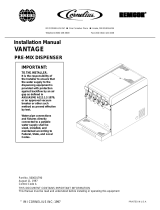
Figure 7
7. Neatly route the opposite ends of the two (2) 8 ft line
assemblies underneath the top of the stand and to the
unit's control panel. Attach the line coming from the pri-
mary regulator marked “A” to the fitting on the “A” side
of the Change-over Valve. Attach the line coming form
the regulator marked “B” to the fitting on the “B” side of
the Change-over Valve (refer to figure 7).
Note: When installing backup regulator kit, a
1
/4" MPT x
3
/8"
MF adaptor should be installed on the “B” side of the Change-
over Valve.
8. Attach the two (2) 8 ft line assemblies to the refrigera-
tion unit stand with the nylon clamp, screw, and washer
provided in kit.
9. Locate the
1
/4" line assembly provided in kit. Attach one (1)
end of the line assembly to the remaining side of the
Change-over Valve. Route remaining end of line assembly
to the CO
2 Supply Manifold and trim excess line accord-
ingly.
11. Connect the swivel nut adaptor (supplied in kit) to the
end of
1
/4" line assembly. Secure with tab clamp. Route
and connect the line assembly to the CO
2 Supply Manifold
(refer to figure 7).
12. Attach the CO
2 warning label to the side of the refrigera-
tion unit (refer to figure 5).
13. Once system is installed turn the handle of the tank
Change-over Valve Assembly to the “A” position. Turn “on”
the CO
2 tank and allow CO2 to enter the stem. Check the
“A” tank pressure gauge. It should read 90 psi (6.2 bar).
If not, adjust the regulator accordingly. Turn the handle
of the tank Change-over Valve to the “B” position and
repeat this procedure.
CO2 Supply
Manifold
“A” Side
“B” Side
To CO
2 Supply
Manifold
/