Page is loading ...

User guide
Please read the sections “Important notice” and “Warnings” at the end of this document
002-34870 Rev. *B
www.infineon.com
2023-06-24
CY8CKIT-040T PSoC™ 4000T CAPSENSE™
Evaluation Kit guide
About this document
Scope and purpose
This guide helps you get acquainted with the CY8CKIT-040T PSoC™ 4000T CAPSENSE™ Evaluation Kit (EVK). The
document explains the kit operation, describes the out-of-the-box (OOB) example and its operation, and the
hardware details of the board.
Intended audience
This kit is intended for all technical specialists familiar with PSoC™ 4 MCU and CAPSENSE™.
Note: This kit is intended to be used under laboratory conditions.

User guide
2
002-34870 Rev. *B
2023-06-24
CY8CKIT-040T PSoC™ 4000T CAPSENSE™ Evaluation Kit guide
Important notice
Important notice
“Evaluation Boards and Reference Boards” shall mean products embedded on a printed circuit board
(PCB) for demonstration and/or evaluation purposes, which include, without limitation, demonstration,
reference and evaluation boards, kits and design (collectively referred to as “Reference Board”).
Environmental conditions have been considered in the design of the Evaluation Boards and Reference
Boards provided by Infineon Technologies. The design of the Evaluation Boards and Reference Boards
has been tested by Infineon Technologies only as described in this document. The design is not qualified
in terms of safety requirements, manufacturing and operation over the entire operating temperature
range or lifetime.
The Evaluation Boards and Reference Boards provided by Infineon Technologies are subject to functional
testing only under typical load conditions. Evaluation Boards and Reference Boards are not subject to the
same procedures as regular products regarding returned material analysis (RMA), process change
notification (PCN) and product discontinuation (PD).
Evaluation Boards and Reference Boards are not commercialized products, and are solely intended for
evaluation and testing purposes. In particular, they shall not be used for reliability testing or production.
The Evaluation Boards and Reference Boards may therefore not comply with CE or similar standards
(including but not limited to the EMC Directive 2004/EC/108 and the EMC Act) and may not fulfill other
requirements of the country in which they are operated by the customer. The customer shall ensure that
all Evaluation Boards and Reference Boards will be handled in a way which is compliant with the relevant
requirements and standards of the country in which they are operated.
The Evaluation Boards and Reference Boards as well as the information provided in this document are
addressed only to qualified and skilled technical staff, for laboratory usage, and shall be used and
managed according to the terms and conditions set forth in this document and in other related
documentation supplied with the respective Evaluation Board or Reference Board.
It is the responsibility of the customer’s technical departments to evaluate the suitability of the
Evaluation Boards and Reference Boards for the intended application, and to evaluate the completeness
and correctness of the information provided in this document with respect to such application.
The customer is obliged to ensure that the use of the Evaluation Boards and Reference Boards does not
cause any harm to persons or third party property.
The Evaluation Boards and Reference Boards and any information in this document is provided "as is"
and Infineon Technologies disclaims any warranties, express or implied, including but not limited to
warranties of non-infringement of third party rights and implied warranties of fitness for any purpose, or
for merchantability.
Infineon Technologies shall not be responsible for any damages resulting from the use of the Evaluation
Boards and Reference Boards and/or from any information provided in this document. The customer is
obliged to defend, indemnify and hold Infineon Technologies harmless from and against any claims or
damages arising out of or resulting from any use thereof.
Infineon Technologies reserves the right to modify this document and/or any information provided
herein at any time without further notice.

User guide
3
002-34870 Rev. *B
2023-06-24
CY8CKIT-040T PSoC™ 4000T CAPSENSE™ Evaluation Kit guide
Safety precautions
Safety precautions
Note: Please note the following warnings regarding the hazards associated with development systems
Table 1 Safety precautions
Caution: The evaluation or reference board contains parts and assemblies sensitive to
electrostatic discharge (ESD). Electrostatic control precautions are required when
installing, testing, servicing or repairing the assembly. Component damage may result
if ESD control procedures are not followed. If you are not familiar with electrostatic
control procedures, refer to the applicable ESD protection handbooks and guidelines.

User guide
4
002-34870 Rev. *B
2023-06-24
CY8CKIT-040T PSoC™ 4000T CAPSENSE™ Evaluation Kit guide
Table of contents
Table of contents
About this document ....................................................................................................................... 1
Important notice ............................................................................................................................ 2
Safety precautions .......................................................................................................................... 3
Table of contents ............................................................................................................................ 4
1 Introduction .......................................................................................................................... 5
1.1 Kit contents ............................................................................................................................................. 6
1.2 Getting started......................................................................................................................................... 7
1.3 Board details ........................................................................................................................................... 7
1.4 Additional learning resources ................................................................................................................. 7
1.5 Technical support.................................................................................................................................... 8
1.6 Documentation conventions .................................................................................................................. 8
2 Kit operation ......................................................................................................................... 9
2.1 Theory of operation ................................................................................................................................. 9
2.2 Using the OOB example – CE234752 ..................................................................................................... 12
2.3 Creating a project and program/debug using ModusToolbox™ software .......................................... 15
3 Hardware ............................................................................................................................. 20
3.1 Schematics ............................................................................................................................................ 20
3.2 Functional description .......................................................................................................................... 20
3.2.1 Features ............................................................................................................................................ 20
3.2.1.1 PSoC™ 4000T device power ........................................................................................................ 21
3.2.1.2 PSoC™ 4000T device 10-pin programming/debugging header ................................................. 23
3.2.1.3 PSoC™ 4000T device 4-pin I2C/UART expansion header ........................................................... 24
3.2.1.4 Reset button ................................................................................................................................ 24
3.2.2 PSoC™ 5LP based KitProg3 programmer and debugger ................................................................ 25
3.2.2.1 KitProg3 onboard target voltage measurement ........................................................................ 26
3.2.2.2 KitProg3 programming mode selection button and status LED ............................................... 26
3.2.3 Power supply system ....................................................................................................................... 27
3.2.3.1 Voltage regulators ....................................................................................................................... 27
3.2.4 CAPSENSE™ ...................................................................................................................................... 28
3.2.4.1 Capacitive sensing ...................................................................................................................... 28
3.2.5 User LED and serial RGB LEDs .......................................................................................................... 29
3.2.6 Enclosure of PSoC™ 4000T CAPSENSE™ EVB .................................................................................. 30
3.3 CY8CKIT-040T kit rework for evaluating additional features .............................................................. 31
3.3.1 Enabling the external programming/debugging interface to PSoC™ 4000T device...................... 31
3.3.2 Enabling the external host I2C/UART interface to PSoC™ 4000T device ........................................ 32
3.3.3 Enabling the KitProg3 UART interface to PSoC™ 4000T device ...................................................... 33
3.4 Bill of materials ...................................................................................................................................... 33
Glossary ....................................................................................................................................... 34
Revision history............................................................................................................................. 36
Disclaimer..................................................................................................................................... 37

User guide
5
002-34870 Rev. *B
2023-06-24
CY8CKIT-040T PSoC™ 4000T CAPSENSE™ Evaluation Kit guide
Introduction
1 Introduction
Wearable technology devices from fitness trackers to smart glasses and smart clothes are becoming
increasingly popular. Capacitive sensing is one of the key features of any wearable solution. Battery life is the
major challenge in any wearable technology today; therefore, there is a constant need to lower the power
consumption while still needing the devices to be ON and responsive all the time.
PSoC™ 4000T series MCU (hereafter called “PSoC™ 4000T”) addresses this challenge by introducing the new
fifth-generation CAPSENSE™ and multi-sense low-power (MSC-LP) technology, offering an ultra-low-power
touch HMI solution based on an integrated “Always-on” sensing technology. It enables scanning low-power
buttons such as power/wakeup buttons while the device is in deep sleep and processing the results to wake the
device in the event of a touch. This technology has an inherent autonomous scanning capability, which doesn’t
need CPU intervention for scanning sensors; the device can be kept in deep sleep while scanning, thus reducing
the power in active mode as well.
The CY8CKIT-040T PSoC™ 4000T CAPSENSE™ EVK lets you evaluate the features of the PSoC™ 4000T device. The
board has the following features:
• A PSoC™ 4000T device
• An onboard programmer/debugger (KitProg3)
• A capacitive button
• A capacitive proximity sensor
• A capacitive touchpad
• User LEDs (both serial RGB and single-color LEDs)
This kit demonstrates the following key capabilities of the fifth-generation CAPSENSE™ technology OOB:
1. Superior touch-sensing performance
− Best-in-class sensitivity, SNR, and immunity to harsh environmental conditions such as temperature and
moisture.
2. Ultra-low-power capability based on “Always-On” sensing.
− Ability to obtain power numbers as low as 3.6 µA in the Wake-On-Touch mode and 74 µA in Active mode
(see CE235111 for the scan conditions for achieving this), making it ideal for battery-operated wearable
devices.
3. Superior liquid tolerance
− The kit can be dipped into liquids such as soap water, seawater, and mineral water up to the immersible
line or sprayed with liquid droplets without reporting any false touches (demonstrated in the CE234752).
− A touchpad with a proximity sensor emulates a wearable screen with a bezel around it. Liquid tolerance
on the touchpad is showcased in the CE234752, even with this loop grounded.
See the AN85951 - PSoC™ 4 and PSoC™ 6 MCU CAPSENSE™ design guide for details of the features of the fifth-
generation CAPSENSE™ - MSC-LP.
You can use ModusToolbox™ software to develop and debug your PSoC™ 4 projects. ModusToolbox™ software
is a set of tools that enables you to integrate Infineon devices into your existing development methodology.
If you are new to PSoC™ 4 and ModusToolbox™ software IDE, see the application note AN79953 - Getting started
with PSoC™ 4 to help familiarize yourself with the PSoC™ 4 and help you create your own design.

User guide
6
002-34870 Rev. *B
2023-06-24
CY8CKIT-040T PSoC™ 4000T CAPSENSE™ Evaluation Kit guide
Introduction
1.1 Kit contents
The CY8CKIT-040T PSoC™ 4000T CAPSENSE™ EVK contains the following, as shown in Figure 1.
• PSoC™ 4000T CAPSENSE™ EVB with enclosure
• USB Type-A to Micro-B cable
• Water dropper
• Quick start guide (part of packaging)
CY8CKIT-040T PSoC™ 4000T CAPSENSE™ EVK contents
Inspect the kit’s contents; if you find any part missing, contact your nearest Infineon sales office for help:
www.infineon.com/support.

User guide
7
002-34870 Rev. *B
2023-06-24
CY8CKIT-040T PSoC™ 4000T CAPSENSE™ Evaluation Kit guide
Introduction
1.2 Getting started
This guide helps you get acquainted with the PSoC™ 4000T CAPSENSE™ EVK:
• See the Kit operation chapter for an overview of PSoC™ 4000T device features and follow section 2.2 to have
a quick review of the OOB project pre-programmed in this kit. It also provides the steps to create a project
and program/debug using the ModusToolbox™ software.
• See the Hardware chapter for detailed hardware description, kit schematics, rework instructions, and the
bill of materials (BOM).
• Use ModusToolbox™ software for application development using the PSoC™ 4000T CAPSENSE™ EVK. See
the kit webpage for the latest software support for this development kit.
− ModusToolbox™ software is a free development ecosystem that includes the Eclipse IDE for
ModusToolbox™ software. Using ModusToolbox™ software, you can enable and configure device
resources, middleware libraries, and program and debug the device. You can download the software
from the ModusToolbox™ software home page. See the ModusToolbox™ software user guide for
additional information.
• See the wide range of code examples to evaluate the PSoC™ 4000T CAPSENSE™ EVB. These examples help
you familiarize yourself with the PSoC™ 4000T device and create your design. You can also find code
examples on the GitHub page dedicated to ModusToolbox™ software-based examples.
− To access code examples through ModusToolbox™ software, see the “Code examples” section in AN79953
- Getting started with PSoC™ 4 under “ModusToolbox™ software resources”.
1.3 Board details
PSoC™ 4000T CAPSENSE™ EVK has the following peripherals:
• PSoC™ 4000T MCU - CY8C4046LQI-T452. See the device datasheet.
• Capacitive touchpad with four rows and five columns supporting self-capacitance (CSD) and mutual-
capacitance (CSX) sensing modes, a capacitive button and a capacitive proximity loop with a 3.5 cm
diagonal length supporting a self-capacitance (CSD) sensing enclosed in a 1.2-mm thick surface of
polycarbonate enclosure (act as overlay) to support smooth touch sensing and liquid-tolerant operation.
• Three serial addressable RGB LEDs, an user LED, and a reset button for the PSoC™ 4000T MCU.
• A Micro-B connector for power input to the kit and KitProg3 USB device interface.
• Selectable input supply voltages of 1.8 V, 3.3 V, and 5 V for the PSoC™ 4000T MCU.
• KitProg3 onboard SWD programmer/debugger, USB-to-UART, and USB-I2C bridge functionality.
• KitProg3 programming mode selection button a status LED
• I2C/UART header provision to interface PSoC™ 4000T device with an external host device.
1.4 Additional learning resources
Infineon provides a wealth of data in the PSoC™ 4 product webpage to help you to select the suitable PSoC™
device for your design and to help you quickly and effectively integrate the device into your design.

User guide
8
002-34870 Rev. *B
2023-06-24
CY8CKIT-040T PSoC™ 4000T CAPSENSE™ Evaluation Kit guide
Introduction
1.5 Technical support
For assistance, visit Infineon support or visit community.infineon.com to ask your questions in the Infineon
developer community.
You can also use the following support resources if you need quick assistance:
• Self-help (Technical documents)
• Local sales office locations
1.6 Documentation conventions
Table 2 Document conventions for guides
Convention
Usage
Courier New
Displays commands, user entered text, and source code:
cd mtb
Italics
Displays file names and reference documentation:
Read about the sourcefile.hex file in the PSoC™ Creator User Guide.
File > Open
Represents menu paths: File > Open > New Project
Bold
Displays commands, menu paths, and icon names in procedures:
Click the File icon and then click Open.
Times New Roman
Displays an equation: 2 + 2 = 4
Text in gray boxes
Describes Cautions or unique functionality of the product.

User guide
9
002-34870 Rev. *B
2023-06-24
CY8CKIT-040T PSoC™ 4000T CAPSENSE™ Evaluation Kit guide
Kit operation
2 Kit operation
This chapter provides an overview of the features of the PSoC™ 4000T device and a quick review of the OOB
project pre-programmed in this kit. It also provides the steps to create a project and program/debug using the
ModusToolbox™ software.
2.1 Theory of operation
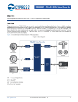
The PSoC™ 4000T CAPSENSE™ EVK is built around a PSoC™ 4000T device. Figure 2 shows the block diagram of
the PSoC™ 4000T device used on the board. For details of device features, see the device datasheet.
Peripherals
CPU Subsystem
System Interconnect (Single Layer AHB)
PSoCTM 4000T
IOSS GPIO (5x ports)
IO Subsystem
Peripheral Interconnect (MMIO)
PCLK
FLASH
64 KB
Read Accelerator
SPCIF
SRAM
8 KB
SRAM Controller
ROM
8 KB
ROM Controller
32-bit
AHB-Lite
1x SCB-I2C/SPI/UART
21x GPIOs (fine pitch)
DeepSleep
Active/Sleep
Power Modes
Digital DFT
Test
Analog DFT
System Resources
Lite
Power
Clock
Reset
Clock Control
IMO
Sleep Control
REFPOR
Reset Control
TestMode Entry
WIC
XRES
WDT
ILO
PWRSYS
2x TCPWM
High Speed I/O Matrix
SWD/TC
NVIC, IRQMUX
Cortex®
M0+
48 MHz
FAST MUL
MSC-LP
REF
IMO
S8PUMP
1x SCB-I2C
PSoC™ 4000T device block diagram

User guide
10
002-34870 Rev. *B
2023-06-24
CY8CKIT-040T PSoC™ 4000T CAPSENSE™ Evaluation Kit guide
Kit operation
Figure 3 shows the block diagram of the PSoC™ 4000T CAPSENSE™ EVB.
KitProg3
(PSoC5LP)
HW ID 0x09
Status LED Mode
Switch
KitProg3 USB
(Micro-B)
Voltage
Monitoring
KitProg3
HW ID
PSoC 4000T
SWD
I2C
No-Load
Non-IFX parts
IFX MCU
Legend
RESET
Reset
Button
GPIO
UART
Proximity
Loop
SWD
10-Pin
Header
User
LED
I2C 4-Pin
Header
Serial RGB
LED
(x3)
CSD
Button
4x5
Keypad
Sensors
Functional block diagram of CY8CKIT-040T PSoC™ 4000T CAPSENSE™ EVK
PSoC™ 4000T CAPSENSE™ EVB details

User guide
11
002-34870 Rev. *B
2023-06-24
CY8CKIT-040T PSoC™ 4000T CAPSENSE™ Evaluation Kit guide
Kit operation
PSoC™ 4000T CAPSENSE™ EVK focuses on demonstrating the capabilities of 5th-generation CAPSENSE™
technology like low power operation with always-on sensing, and improved touch sensing performance with
robust and liquid tolerant CAPSENSE™ widgets using PSoC™ 4000T device. This kit supports the following
features:
1. PSoC™ 4000T device (CY8C4046LQI-T452, U1): This kit highlights the features of the PSoC™ 4000T device
and has been designed for the 24-pin QFN part with 64KB flash capacity.
2. PSoC™ 4000T device I2C/UART interface header (J8) (footprint only): This 4-pin header provision allows
to interface of the PSoC™ 4000T device with an external host device over I2C/UART.
3. PSoC™ 5LP-based KitProg3 programmer and debugger (CY8C5868LTI-LP039, U2): The PSoC™ 5LP
device (CY8C5868LTI-LP039) serving as KitProg3 is a multi-functional system, which includes an SWD
programmer, debugger, USB-I2C bridge, and USB-UART bridge. For more details, see the KitProg3 user
guide.
4. KitProg3 programming mode selection button (SW3): This button is used to get into the Bootloader
mode. The button connects the PSoC™ 5LP pin to the ground when pressed. For more details, see the
KitProg3 user guide.
5. Voltage regulator (TLS205B0LDVXUMA1; U15 and U16): The kit has two onboard regulators configured to
generate 1.8 V and 3.3 V; the input voltage to the regulator is derived from the USB connector.
6. PSoC™ 4000T device reset button (SW1): This button resets the PSoC™ 4000T device. It connects the
PSoC™ 4000T device reset (XRES) pin to the ground when pressed.
7. PSoC™ 4000T device current measurement header (J4): An ammeter can be connected to this header to
measure the current consumed by the PSoC™ 4000T device.
8. Target voltage selection switch (SW2): A slide switch (SW2) to select the 5 V, 3.3 V, and 1.8 V target
voltages.
9. KitProg3 USB connector (J1): Use the USB cable provided along with the EVB to connect the board to a PC
to power the board and program/debug using the KitProg3 onboard programmer and debugger.
10. Programming header for PSoC™ 5LP (J2) (footprint only): This 5-pin header provision can be used to
program the PSoC™ 5LP device. By default, the PSoC™ 5LP device is loaded with KitProg3 firmware.
11. PSoC™ 4000T device program and debug interface header (J6) (footprint only): This 10-pin standard
SWD/JTAG header provision allows to interface external programmers such as MiniProg4 for programming
and debugging.
12. Power LED (LED4 - Green): Indicates the status of the power supplied to the board.
13. KitProg3 status LED (LED5 - Green): Indicates the status of the KitProg3. See the KitProg3 user guide.
14. Single color user LED (LED6): This user LED operates at the entire operating voltage range of the
PSoC™ 4000T device. The LED is active LOW; therefore, the pin must be driven to the ground to turn ON the
LED.
15. Serial RGB LED (U12, U13, and U14): These three user LEDs are serial RGB LEDs driven by the SPI master
and operate at the entire operating voltage range of the PSoC™ 4000T device. These can be used to show
the capacitive button and touchpad statuses.
16. Capacitive button (CSB1): One 7-mm diameter capacitive sensing button, configured as a self-capacitance
(CSD) button, allows you to evaluate Infineon’s fifth-generation CAPSENSE™ technology. It has a 1.2-mm
thick surface of polycarbonate enclosure for smooth touch sensing.
17. Capacitive CSD Proximity Sensor (CSP1): Capacitive proximity loop with 3.5 cm diagonal length.
18. Capacitive Touchpad (CST1): 20-segment capacitive touchpad that has four rows and five columns, which
can be configured as a self-capacitance (CSD) touchpad or a mutual-capacitance (CSX) touchpad.
See 3.2 Functional description for details on various hardware blocks.

User guide
12
002-34870 Rev. *B
2023-06-24
CY8CKIT-040T PSoC™ 4000T CAPSENSE™ Evaluation Kit guide
Kit operation
2.2 Using the OOB example – CE234752
The PSoC™ 4000T CAPSENSE™ EVB is pre-programmed with the CE234752 – PSoC™ 4: MSC-LP robust low-power
liquid-tolerant CAPSENSE™ code example (CE). This CE demonstrates the key features of fifth-generation
CAPSENSE™ technology in PSoC™ 4000T, such as the following:
• Robust operation of the capacitive touchpad and capacitive button
• Low-power wake-on-touch approach using a ganged sensor (power consumption is optimized for battery-
powered devices)
• Tolerance in the presence of various liquids (immersible in freshwater and saltwater)
Do the following to use the example. For a detailed description of the project, see the example’s README file in
the GitHub repository or from the application’s top-level directory when the example has been created using
ModusToolbox™ software.
Note: At any point in time, if you overwrite the OOB example, you can restore it by programming the
PSoC™ 4: MSC-LP Robust Low-Power Liquid-Tolerant CAPSENSE™ code example. See Creating a
project and program/debug using ModusToolbox™ software for programming the board. Ensure
that the voltage selection switch (SW2) must be at the 1.8 V position.
1. Connect the board to your PC using the provided USB cable through the KitProg3 USB connector as Figure 5
shows. Ensure that the voltage selection switch (SW2) is at 1.8 V before programming the OOB code
example.
Connect USB cable to USB connector on the board
2. Touch the Capacitive button with your finger and observe the LED1 (U12) turn ON with blue color as
Figure 6 shows.

User guide
13
002-34870 Rev. *B
2023-06-24
CY8CKIT-040T PSoC™ 4000T CAPSENSE™ Evaluation Kit guide
Kit operation
CAPSENSE™ button operation with LED indication
3. Touch the touchpad with your finger as shown in the image and observe that LED1 (U12) and LED3 (U14)
turn ON in green with medium brightness as Figure 7 shows.
a) Move your finger horizontally and observe the variation in the brightness of LED1 (U12) accordingly.
b) Move your finger vertically and observe the variation in the brightness of LED3 (U14) accordingly.
Capacitive touchpad operation with LED indication
4. Evaluate the low-power performance by measuring the current values in active, active low refresh rate, and
wake-on-touch modes as explained in the “Measure current at different application states” section of the
code example’s README.
5. Evaluate the water tolerance performance by doing the following and observe that there is no false touch
triggered (no serial RGB LEDs are ON):
Attention: Immerse the kit until the immersible line because there is an opening on the top side of the
enclosure. Before immersion of the kit in water, ensure that the enclosure is assembled
correctly.

User guide
14
002-34870 Rev. *B
2023-06-24
CY8CKIT-040T PSoC™ 4000T CAPSENSE™ Evaluation Kit guide
Kit operation
a) Spray water droplets on top of the widgets, as shown in Figure 8.
Water tolerance with water droplets sprayed on sensors
a) Place water droplets on top of the sensors using a water dropper.
b) Dip the kit inside the water (up to the immersible line) for some time and remove it. Repeat it multiple
times. Observe that all LEDs are in an OFF state continuously, indicating that no false trigger occurs
because of water immersion.
Immersing the kit inside water (up to immersible line)
See the README file of the PSoC™ 4: MSC-LP robust low-power liquid-tolerant CAPSENSE™ code example for
further evaluation of the performance using the CAPSENSE™ Tuner.

User guide
15
002-34870 Rev. *B
2023-06-24
CY8CKIT-040T PSoC™ 4000T CAPSENSE™ Evaluation Kit guide
Kit operation
Note: More code examples are available in Eclipse IDE for ModusToolbox™ software (see Figure 13) or on
the GitHub page dedicated to ModusToolbox™ software based examples to evaluate the board:
PSoC™ 4: Blinky, PSoC™ 4: MSC LP CAPSENSE™ low power, PSoC™ 4: MSC-LP self-capacitance
button tuning, etc.
2.3 Creating a project and program/debug using ModusToolbox™ software
This section briefly introduces project creation, programming, and debugging using ModusToolbox™ software.
For detailed instructions, see Help > ModusToolbox™ General Documentation > ModusToolbox™ User Guide
1. Connect the board to the PC using the USB cable through the KitProg3 USB connector (J1).
The kit enumerates as a USB composite device if you are connecting it to your PC for the first time. KitProg3
operates in CMSIS-DAP Bulk mode; the status LED (green) is always ON in CMSIS-DAP Bulk mode.
If you do not see the correct LED status, see the KitProg3 user guide for details on the KitProg3 status and
troubleshooting instructions.
Connect the USB cable to the USB connector on the board
2. In Eclipse IDE for ModusToolbox™ software, import the required code example (application) into a new
workspace.
a) On the Quick Panel tab, click New Application.
New Application in Quick Panel

User guide
16
002-34870 Rev. *B
2023-06-24
CY8CKIT-040T PSoC™ 4000T CAPSENSE™ Evaluation Kit guide
Kit operation
On the Choose Board Support Package (BSP) - Project Creator 2.0 window, expand PSoC™ 4 BSPs, select
CY8CKIT-040T, and click Next, as shown in Figure 12.
Creating a new application: Choose Board Support Package

User guide
17
002-34870 Rev. *B
2023-06-24
CY8CKIT-040T PSoC™ 4000T CAPSENSE™ Evaluation Kit guide
Kit operation
b) Select the required application and click Create, as shown in Figure 13.
The right pane shows the description of the code example and the link to view the README file on GitHub.
Creating a new application: Select Application

User guide
18
002-34870 Rev. *B
2023-06-24
CY8CKIT-040T PSoC™ 4000T CAPSENSE™ Evaluation Kit guide
Kit operation
3. To build and program a PSoC™ 4000T device application, in the Project Explorer tab, select <App_Name>
project. In the Quick Panel tab, scroll to the Launches section, and click the <App_Name> Program
(KitProg3_MiniProg4) configuration, as shown in Figure 14.
Building and programming the code example

User guide
19
002-34870 Rev. *B
2023-06-24
CY8CKIT-040T PSoC™ 4000T CAPSENSE™ Evaluation Kit guide
Kit operation
4. ModusToolbox™ software has an integrated debugger. To debug a PSoC™ 4000T device application, in the
Project Explorer tab, select <App_Name> project. In the Quick Panel, scroll to the Launches section, and
click the <App_Name> Debug (KitProg3_MiniProg4) configuration, as shown in Figure 15. For a detailed
explanation on how to debug using ModusToolbox™ software, see “Program and debug” section in Eclipse
IDE for ModusToolbox™ user guide.
Debugging the code example

User guide
20
002-34870 Rev. *B
2023-06-24
CY8CKIT-040T PSoC™ 4000T CAPSENSE™ Evaluation Kit guide
Hardware
3 Hardware
3.1 Schematics
See the schematic files available on the kit webpage.
3.2 Functional description
This section describes the individual hardware blocks. The kit comes with a PSoC™ 4000T CAPSENSE™ EVB. It
consists of the PSoC™ 4000T device, KitProg3 programmer/debugger and bridge, voltage regulators,
CAPSENSE™ button, CAPSENSE™ proximity sensor, CAPSENSE™ 4x5 touchpad, user LED, serial RGB LEDs, and
other passives required for the essential operation of the kit.
3.2.1 Features
This kit features a PSoC™ 4000T device, a member of the PSoC™ 4 platform with scalable and reconfigurable
architecture with an Arm® Cortex®-M0+ CPU. It combines a high-performance capacitive sensing subsystem,
and programmable, reconfigurable analog and digital blocks.
For more information, see the PSoC™ 4000T device family datasheet.
Schematics of the PSoC™ 4000T device
Table 3 Pin assignment of PSoC™ 4000T device in the EVB
Pin details
Primary onboard function
Secondary onboard function
P0[0]
Capacitive touchpad (CST_C4) – Col4
–
P0[1]
Capacitive touchpad (CST_C3) – Col3
–
P0[2]
Capacitive touchpad (CST_C2) – Col2
–
P0[3]
Capacitive touchpad (CST_C1) – Col1
–
P0[4]
Capacitive touchpad (CST_C0) – Col0
–
P1[0]
Capacitive touchpad (CST_R3) – Row3
–
P2[0]
Capacitive touchpad (CST_R2) – Row2
–
P2[1]
Capacitive touchpad (CST_R1) – Row1
–
/