Page is loading ...

865 STYLE W/X NOTIFICATION
MODULE
Installation Guide
DESCRIPTION
5
6
7
8
9
10
11
4
3
2
1
AUX
PWR
TRBL
BELL
SILENCE
BELL POWER
GROUNDED
AT PANEL
NORMAL
MODEL 865
GND
FAU LT
GND
ALARM
INPUT
BELL
PWR +
INPUT
BELL
PWR -
INPUT
BELL A+
OUTPUT
BELL A-
OUTPUT
BELL B+
OUTPUT
BELL B-
OUTPUT
BELL
TRBL
BELL
TRBL
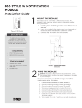
The 865 NAC module provides
Style W or X supervision for
ground faults, opens, and shorts
on notification appliance circuits
connected to fire alarm control
panels. The 865 is suitable for use
with 2 or 4-wire circuits.
The module also includes a Trouble
LED, Ground Fault LED, and a set of
Normally Closed Trouble contacts
to indicate o normal conditions.
Additionally, the module includes
a Bell Silence switch for use during
testing or service.
Connect a maximum 5 Amp,
12 or 24 VDC regulated, power
limited power supply listed for Fire
Protective Signals to the module to
support alarm power requirements
beyond the panel alarm output
capacity.
Compatibility
• XT30/XT50 Series panels
• XR150/XR550 Series panels
What is Included?
• One 865 NAC Module
• One Model 308 10k Ohm Resistor
with Leads
• Hardware Pack
1
MOUNT THE MODULE
Themodule can be mounted in a
DMP enclosure using the standard
3-hole mounting pattern. Refer
to Figure 2 as needed during
installation.
1. Hold the plastic standos
against the inside of the
enclosure side wall.
2. Insert the included Phillips
head screws from the
outside of the enclosure into
the standos. Tighten the
screws.
3. Carefully snap the module
onto the standos.
WIRE THE MODULE
2
Caution: Disconnect all power from the panel before wiring
the module. Failure to do so may result in equipment damage
or personal injury.
For power connections, use 22 AWG or larger wire. Refer to
Figure 3 and Figure 4 when wiring themodule.
1. Connect module Terminal 1 to panel Terminal 7.
2. Connect module Terminal 2 to panel Terminal 10.
3. Connect module Terminal 3 to panel Terminal 5.
4. Wire power supply positive to module Terminal 4.
5. Wire power supply negative to module Terminal 5.
6. If powering the NACs from the control panel, connect a
jumper between module Terminals3 and 4 and between
Terminals 2 and 5. For supervised circuits, ground fault is
detected at 0 (zero) Ohms.
7. For Style W connections, wire module Terminals 6-11
as shown in Figure 3. Install the included 10k Ohm EOL
resistor across Bell Output A + and Bell Output A –.
8. For Style X connections, wire module Terminals 6-11 as
shown in Figure 4. Trouble contacts are connected to a
zone on the panel to indicate NAC trouble or ground faults.
The common relay is rated 30 VDC @ 1 Amp, resistive.
9. For Style W and Style X circuits, install a jumper on the
Bell Ground Header. The jumper also disables the alarm
bell output in the event of a ground fault on either side of
the notification circuit.
Figure 1: 865 Module
Figure 2: Stando and Module
Installation
BACK
1
2
3

Designed, engineered, and
manufactured in Springfield, MO
using U.S. and global components.
LT-0179 1.02 20145
865 STYLE W/X
NOTIFICATION MODULE
Specifications
Operating Voltage
Terminal 1 9.6 to 14.2VDC
Operating Current
Terminal 1 26mA idle and 85mA in alarm
Terminal 3 33mA max
Max Alarm Current
Terminal 4 30VDC @ 5Amps with listed power supply
Ordering Information
865 Style W/X Notification Module
Accessories
308 10k Ohm Replacement Resistor
Compatibility
XT30/XT50 Series Panels
XR150/XR550 Series Panels
Certifications
California State Fire Marshal (CSFM)
New York City (FDNY COA #6167)
Underwriters Laboratory (UL) Listed
ANSI/UL 1023 Household Burglar Alarm System Units
ANSI/UL 864 Fire Protective Signaling Systems
5
6
7
8
9
10
11
4
3
2
1
AUX
PWR
TRBL
BELL
SILENCE
BELL POWER
GROUNDED
AT PANEL
NORMAL
MODEL 865
GND
FAULT
GND
ALARM
INPUT
BELL
PWR +
INPUT
BELL
PWR -
INPUT
BELL A+
OUTPUT
BELL A-
OUTPUT
BELL B+
OUTPUT
BELL B-
OUTPUT
BELL
TRBL
BELL
TRBL
INTRUSION • FIRE • ACCESS • NETWORKS
2500 North Partnership Boulevard
Springfield, Missouri 65803-8877
800.641.4282 | DMP.com
© 2020
ADDITIONAL INFORMATION
Wiring Specifications
DMP recommends using 18 or 22 AWG for all LX-Bus and Keypad Bus connections. The maximum wire distance between
any module and the DMP Keypad Bus or LX-Bus circuit is 10 feet. To increase the wiring distance, install an auxiliary
power supply, such as a DMP Model 505-12. Maximum voltage drop between a panel or auxiliary power supply and any
device is 2.0 VDC. If the voltage at any device is less than the required level, add an auxiliary power supply at the end of
the circuit.
To maintain auxiliary power integrity when using 22-gauge wire on Keypad Bus circuits, do not exceed 500 feet. When
using 18-gauge wire, do not exceed 1,000 feet. Maximum distance for any bus circuit is 2,500 feet regardless of wire
gauge. Each 2,500 foot bus circuit supports a maximum of 40 LX-Bus devices.
For additional information refer to the LX-Bus/Keypad Bus Wiring Application Note (LT-2031) and the 710 Bus Splitter/
Repeater Module Installation Guide (LT-0310).
Bell Silence Switch
A bell silence toggle prevents the indicating device from sounding during a system test. When the Bell Silence position
is selected, a 15-second delay occurs before the module bell trouble contacts open. After testing, return the bell silence
switch to the Normal position to return the module to normal operation.
LED Operation
• Trouble: Lights during an open, short, or short-to-ground on the indicating circuit.
• Ground Fault: Lights during a short-to-ground on the indicating circuit.
5
6
7
8
9
10
11
4
3
2
1
AUX
PWR
TRBL
BELL
SILENCE
BELL POWER
GROUNDED
AT PANEL
NORMAL
MODEL 865
2-WIRE
(STYLE W)
GND
FAULT
GND
ALARM
INPUT
BELL
PWR +
INPUT
BELL
PWR -
INPUT
BELL A+
OUTPUT
BELL A-
OUTPUT
BELL B+
OUTPUT
BELL B-
OUTPUT
BELL
TRBL
BELL
TRBL
To Panel Terminal 7
To Panel Terminal 10
To Panel Terminal 5
From Power Supply +
From Power Supply –
+
–
To Bell Output A –
To Bell Output A +
To N/C Trouble Contact
To N/C Trouble Contact
Bell Silence Toggle
Bell Ground Header
Trouble and Ground Fault LEDs
10k Ω EOL
Optional Jumpers
5
6
7
8
9
10
11
4
3
2
1
AUX
PWR
TRBL
BELL
SILENCE
BELL POWER
GROUNDED
AT PANEL
NORMAL
MODEL 865
4-WIRE
(STYLE X)
GND
FAULT
GND
ALARM
INPUT
BELL
PWR +
INPUT
BELL
PWR -
INPUT
BELL A+
OUTPUT
BELL A-
OUTPUT
BELL B+
OUTPUT
BELL B-
OUTPUT
BELL
TRBL
BELL
TRBL
To Panel Terminal 7
To Panel Terminal 10
To Panel Terminal 5
From Power Supply +
From Power Supply -
To Bell Output A +
To Bell Output A
–
To Bell Output B +
To Bell Output B
–
To N/C Trouble Contact
To N/C Trouble Contact
+
–
Bell Silence Toggle
Bell Ground Header
Trouble and Ground Fault LEDs
Optional Jumpers
Figure 3: Style W Wiring Connections Figure 4: Style X Wiring Connections
/