Page is loading ...

866 STYLE W NOTIFICATION
MODULE
Installation Guide
DESCRIPTION
5
6
7
8
4
3
2
1
AUX
PWR
GND
ALARM
INPUT
BELL
PWR +
INPUT
BELL +
OUTPUT
BELL -
OUTPUT
BELL
TRBL
BELL
TRBL
BELL
SILENCE
NORMAL
MODEL 866
The 866Notification Module
provides one 5Amp Style W
notification circuit for supervising
listed, polarized notification devices
such as bells, strobes, and horns.
Compatibility
• XT30/XT50Series panels
• XR150/XR550Series panels
What is Included?
• One 866NAC Module
• One Model 308 10k Ohm Resistor
with Leads
• Hardware Pack
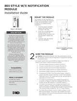
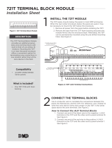
1MOUNT THE MODULE
Themodule can be mounted in a DMP enclosure using the
standard3‑hole mounting pattern. Refer to Figure 2 as needed
during installation.
1. Hold the plastic standos against the inside of the enclosure
side wall.
2. Insert the included Phillips head screws from the outside of
the enclosure into the standos. Tighten the screws.
3. Carefully snap the module onto the standos.
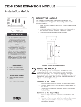
WIRE THE MODULE
2Caution: Disconnect all power from the panel before wiring
the module. Failure to do so may result in equipment damage
or personal injury.
For power connections, use 22AWG or larger wire. Refer to
Figure 3 when wiring themodule.
1. Connect module Terminal 1to panel Terminal 7.
2. Connect module Terminal 2to panel Terminal 10.
3. Connect module Terminal 3to panel Terminal 5.
4. Wire power supply positive to module Terminal 4.
5. Connect module Terminal 5to bell output positive.
6. Connect module Terminal 6to bell output negative.
7. Install the included 10k Ohm EOL resistor across module
Terminals5and 6.
8. Wire module Terminals 7and 8to a normally closed zone.
Figure 1: 866 Module
Figure 2: Stando and Module
Installation
BACK
1
2
3

Designed, engineered, and
manufactured in Springfield, MO
using U.S. and global components.
LT-0059 1.02 22295
866 STYLE W
NOTIFICATION MODULE
Specifications
Operating Current (from panel)
Standby: 45 mA
Alarm: 76 mA
Alarm Contact Rating 5 Amps @ 24 VDC resistive
Trouble Contact Rating 2 Amps @ 30 VDC resistive
Maximum impedance 100 Ohms
Ordering Information
866 Style W Notification Module
Accessories
308 10k Ohm Replacement Resistor
Compatibility
XT30/XT50 Series Panels
XR150/XR550 Series Panels
Certifications
California State Fire Marshal (CSFM)
New York City (FDNY)
Underwriters Laboratory (UL) Listed
ANSI/UL 1023 Household Burglar Alarm System Units
ANSI/UL 985 Household Fire Warning
ANSI/UL 864 Fire Protective Signaling Systems
5
6
7
8
4
3
2
1
AUX
PWR
GND
ALARM
INPUT
BELL
PWR +
INPUT
BELL +
OUTPUT
BELL -
OUTPUT
BELL
TRBL
BELL
TRBL
BELL
SILENCE
NORMAL
MODEL 866
INTRUSION • FIRE • ACCESS • NETWORKS
2500 North Partnership Boulevard
Springfield, Missouri 65803-8877
800.641.4282 | DMP.com
© 2022
ADDITIONAL INFORMATION
Programming
Program the trouble contacts on the module and the auxiliary
power supply as a Supervisory Zone (SV) selected for display in
the keypad status list. Refer to the appropriate panel programming
guide for more information.
Auxiliary Power Supply Supervision
The panel supervises the regulated, power limited auxiliary power
supply listed for Fire Protective Signals through the normally closed
trouble contacts on the power supply. The power supply trouble
contacts connect to Terminals7and8 on the module. The module
provides a relay and two bell trouble contacts at Terminals 7 and 8
to connect the zone input from the panel. When the bell circuit is in
a bad condition, these terminals provide an open condition to the
zone. These trouble contacts are rated for up to 2Amps at 30VDC
resistive. An open circuit causes an open condition to be reported to
the panel. For wiring information, refer to Figure 3.
Bell Silence Toggle
A bell silence toggle prevents the indicating device from sounding during a system test. When the Bell Silence position
is selected, a 15‑second delay occurs before the module bell trouble contacts open. After testing, return the bell silence
switch to the Normal position to return the module to normal operation.
BELL
SILENCE
NORMAL
MODEL 866
2-WIRE
(STYLE W)
Bell Silence Toggle
5
6
7
8
4
3
2
1
AUX
PWR
GND
ALARM
INPUT
BELL
PWR +
INPUT
BELL +
OUTPUT
BELL -
OUTPUT
BELL
TRBL
BELL
TRBL
To Panel Terminal 7
To Panel Terminal 10
To Panel Terminal 5
From Power Supply +
+
–
To Bell Output –
To Bell Output +
10k Ω EOL
To Bell Trouble Contact
To Bell Trouble Contact
866 Module Trouble Contacts
Normal = Contacts Shorted
Trouble = Contacts Open
Figure 3: Style W Wiring Connections
/