Page is loading ...

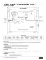
MODEL 505-12 POWER SUPPLY
WIRING DIAGRAM
LT-0454 1.02 © 2019 Digital Monitoring Products, Inc.
19151
DC
AC
Trouble
Batt
Trouble
Input:
120 VAC 60 Hz
1.5 Amps
Unswitched
Green
LED
AC
NAC
Module
GRAY
VIOLET
Red
LED
DC
RED
Battery Wires
(included)
AC and battery
output relay
connections
For Access Control
Applications (UL 294)
install a Model 307
Tamper Switch.
Factory
Installed
12 VDC @ 5 Amps
Output:
16 VAC @ 100 VA
Power Limited / Class 2
wire routing through
conduit knockouts
Battery
Start
Ground
wire
attached
to the
inside of
the
enclosure
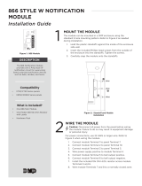
Optional DMP
Notication Modules.
See Figures 1, 2, and 3.
BLACK
BAT
To 867 NAC
Module
or panel
trouble zone
To panel
tamper zone
To Earth
Ground
BLACK
WHITE
GREEN
To NAC
Normal
Bell Silence
Model
866 NAC
Module
Figure 2: Conventional Class B NAC
From
505-12
DC
1 Aux Power
2 Ground
3 Alarm Input
4 Bell Power + Input
5 Bell + Output
6 Bell - Output
7 Bell Trouble
8 Bell Trouble
TRBL
GND
FAU LT
Model
865 NAC
Module
Figure 3: Conventional Class B NAC
To panel Terminal 5
To panel Terminal 10
To panel Terminal 7
To panel Terminal 5
To panel Terminal 10
To panel Terminal 7
1 Aux Power
2 Ground
3 Alarm Input
4 Bell Power + Input
5 Bell Power - Input
6 Bell A+ Output
7 Bell A- Output
8 Bell B+ Output
9 Bell B- Output
10 Bell Trouble
11 Bell Trouble
AC
Trouble
Batt
Trouble
From panel LX Bus
Bell Address
Supervisory Address
Bell Normal
Bell Silence
Model
867 NAC
Module
Figure 1: Addressable Power Booster
Model 505-12LX
1 Bell + Input
2 Bell - Input
3 Bell + Output
4 Bell - Output
5 Bell Trouble
6 Bell Trouble
7 Power Monitor
8 MON RTN
From 505-12
Model 505-12
NAC
Module
DC
From
505-12
DC
From
505-12
This area ts approximately two batteries.
Output Current
Output
Voltage
Voltage Type Normal Standby Standby Battery Min
Operating Time
Maximum
(Alarm)
Standby Battery Operating
Time
Ripple
Voltage
12VDC Direct Current 1.25Amps 24Hours 5.0Amps 5Minutes 350mV
Refer to the 505-12 Installation Guide (LT-0453) for complete descriptions of wiring connections and NAC Module information.
Specifications
12VDC Power Supply 5Amp Maximum
For UL 603 and UL 294 10.76-12.36VDC at 1.25Amps normal standby and 5Amps alarm
Note: Not intended to provide power for sounding devices in UL 609 Local Burglar System
Secondary Power Supply
1.5Amps maximum charge current. Use only 12VDC batteries. Replace every 3-5 years. Refer to LT-0453 for installation details.
Power Limited
All circuits in the Model 505 comply with the requirements for inherent power limitation and are Class 2 with exception of the red battery wire.
NFPA
This equipment should be installed in accordance with the Standard Fire-Protective Signaling Service (National Fire Protection Association,
Batterymarch Park, Quincy MA 02269)
Certifications
UL 1481 Power Supplies for Fire Protective Signaling Systems
UL 603 Power Supplies for Burglary Alarm Systems
UL 294 Power Supplies for Access Control System Units
/