Page is loading ...

Owners Manual
Models:
Xxx-xxx
US Water Systems Corporate Office
1209 Country Club Road
Indianapolis, IN 46234
info@uswatersystems.com
www.uswatersystems.com
1-800-608-8792
Visit us online at
www.uswatersystems.com
REVISION # 1.2
REVISION DATE June 28, 2017
US Water Systems Residential/Commercial
Fusion NLT Super-Filter

2
Safety Guide
Check and comply with your provincial /
state and local codes. You must follow
these guidelines.
Use care when handling the filter tank. Do
not turn upside down, drop, drag or set on
sharp protrusions.
The system works on 12 volt-60 Hz electri-
cal power only. Be sure to use only the in-
cluded transformer.
Transformer must be plugged into an in-
door 120 volt, grounded outlet only.
WARNING: This system is not intend-
ed for treating water that is microbiologi-
cally unsafe or of unknown quality without
adequate disinfection before or after the
system.
For your safety, the information in this manual must be followed to minimize the risk of elec-
tric shock, property damage or personal injury.
Be sure to check the entire unit for any shipping damage or missing parts. Also note damage
to the shipping cartons. Contact US Water Systems at 1-800-608-8792 for all damage and
loss claims. A damage claim must be made within 24 hours of receipt of the unit or the claim
may not be honored.
Small parts, needed to install the filter, are in a parts bag. To avoid loss of the small parts,
keep them in the parts bag until you are ready to use them.
Unpacking / Inspection
PAGE
Unpacking / Inspection 2
Safety Guide 2
Proper Installation 3
Specification 4
Before Starting Installation 5
Sizing Requirements 7
Installation Instructions 8
System Start Up 10
About The System 12
Maintenance 14
Main Repair Parts 16
Trouble Shooting 23
Warranty 24
Table of Contents
Installation, Operation and Maintenance Manual
Models: XXX

3
Proper Installation
This water filter system must be properly installed and located in accordance with the
Installation Instructions before it is used.
Do not install or store where it will not
be exposed to temperatures below freez-
ing or exposed to any type of weather.
Water freezing in the system will break it.
Do not attempt to treat water over 100°F.
Do not install in direct sunlight. Exces-
sive sun or heat may cause distortion or
other damage to non-metallic parts.
Properly ground to conform with all gov-
erning codes and ordinances.
Use only lead-free solder and flux for all
sweat-solder connections, as required by
state and federal codes.
Maximum allowable inlet water pressure is
125 psi. If daytime pressure is over 80 psi,
night time pressure may exceed the maxi-
mum. Use a pressure reducing valve to
reduce the pressure if necessary.
WARNING: Discard all unused parts
and packaging material after installation.
Small parts remaining after the installation
could be a choke hazard.
Installation, Operation and Maintenance Manual
Models: XXX

4
Specifications
Continuous operation at flow rates greater than the ser-
vice flow rate may affect capacity and efficiency perfor-
mance.
The manufacturer reserves the right to make product
improvements which may deviate from the specifications
and descriptions stated herein, without obligation to
change previously manufactured products or to note the
change.
Peak flow rates are intended for intermittent use only and
are for residential application only
At the stated service flow rates, the pressure drop
through these devices will not exceed 15 psig
Installation, Operation and Maintenance Manual
Models: XXX

5
Carbon Filter (Activated Carbon)
Unpleasant tastes and doors caused by chlo-
rine or organic substances, such as decayed
vegetation and run off, are absorbed by top
quality activated carbon. The filter will auto-
matically backwash to a predetermined
schedule. This frees the bed of accumulated
impurities and readies it for operation again.
Filter Ag Filter (Sediment)
Suspended particulate matter such as clay
and silt, which gives water a cloudy appear-
ance, is trapped in the filter bed to produce
clean, clear water. Gravel and Filter Ag Plus
facilitates more thorough backwashing and
prevents channeling. Periodic backwashing
cleans the bed.
Calcite Filter
The neutralizing filter contains blended media
which raises the pH of acidic water and neu-
tralizes its corrosive characteristics. In addi-
tion to protecting pipes, plumbing fixtures and
appliances, this filter also helps with the re-
moval of iron and manganese by raising the
pH. This enables an iron removal system to
operate optimally. Periodic backwashing
cleans the bed. Media replenishment may be
required six months to two years after instal-
lation, depending on the water’s pH and wa-
ter usage.
Before Starting Installation
Tools, Pipe, and Fittings, Other Materials
Pliers
Screwdriver
Teflon tape
Razor knife
Two adjustable wrenches
Additional tools may be required if modifi-
cation to home plumbing is required.
Plastic inlet and outlet fittings are included
with the filter. To maintain full valve flow,
3/4” or 1” pipes to and from the filter fittings
are recommended. The same, or larger,
pipe size should be maintained as the wa-
ter supply pipe, up to the filter inlet and
outlet.
Use copper, brass, or PEX pipe and fit-
tings.
Some codes may also allow PVC plastic
pipe.
ALWAYS install the included bypass valve,
or 3 shut-off valves. Bypass valves allow
the water to the filter to be shut off for re-
pairs if needed, but still have water in the
house pipes.
5/8” OD drain line is needed for the valve
drain.
Installation, Operation and Maintenance Manual
Models: XXX

6
Place the filter tank as close as possible to
the pressure tank (well system) or water
meter (city water).
Place the filter tank as close as possible to
a floor drain, or other acceptable drain
point (laundry tub, sump, standpipe, etc.).
Connect the filter to the main water supply
pipe BEFORE the water heater. DO NOT
RUN HOT WATER THROUGH THE FIL-
TER. Temperature of water passing
through the filter must be less than 100
deg. F.
Do not install the filter in a place where it
could freeze. Damage caused by freezing
is not covered by the warranty.
Put the filter in a place water damage is
least likely to occur if a leak develops. The
manufacturer will not repair or pay for wa-
ter damage.
A 120 volt electric outlet, to plug the includ-
ed transformer into, is needed within 6 feet
of the filter. The transformer has an at-
tached 6 foot power cable. Be sure the
electric outlet and transformer are in an
inside location, to protect from wet
weather.
If installing in an outside location, you must
take the steps necessary to assure the fil-
ter, installation plumbing, wiring, etc., are
as well protected from the elements, con-
tamination, vandalism, etc., as when in-
stalled indoors.
Keep the filter out of direct sunlight.
The sun’s heat may soften and distort
plastic parts.
Where To Install The Filter
Installation, Operation and Maintenance Manual
Models: XXX

7
IMPORTANT—PLEASE REFER TO THE PICTURE BELOW ON INLET/OUTLET SIDE OF THE VALVE
3-Valve Bypass Layout Drawing with Pressure Gauges
Installation, Operation and Maintenance Manual
Models: XXX

8
Typical Backwashing Filter
Installation, Operation and Maintenance Manual
Models: XXX

9
1. Remove the tank from carton.
2. Verify the distributor tube is centered
in the bottom center of the tank. A
flashlight may be necessary.
Installation, Operation and Maintenance Manual
Models: XXX
Fusion Backwashing Filter Tank Preparation
WATER PRESSURE: A minimum of 20 pounds of water pressure is required for regeneration valve to
operate effectively.
ELECTRICAL FACILITIES: An uninterrupted alternating current (A/C) supply is required. Note: Other
voltages are available. Please make sure your voltage supply is compatible with your unit before in-
stallation.
EXISTING PLUMBING: Condition of existing plumbing should be free from lime and iron buildup. Pip-
ing that is built up heavily with lime and/or iron should be replaced.
LOCATION OF INFUSION TANK AND DRAIN: The Infusion tank should be located close to a drain to
prevent air breaks and back flow.
BY-PASS VALVES: Always provide for the installation of a by-pass valve if unit is not equipped with
one.
CAUTION: Water pressure is not to exceed 80 psi, water temperature is not to exceed 110°F (43°C),
and the unit cannot be subjected to freezing conditions.

10
Installation, Operation and Maintenance Manual
Models: XXX
3. Place a piece of duct tape over the distributor tube so no gravel or media enters the
opening while filling.
4. Use the Blue Funnel provided, to pour the GRAVEL in FIRST and the MEDIA in SEC-
OND. Pour gravel and media evenly around the hole to ensure it is well distributed
in the tank. Pour it slow enough, to prevent the funnel from plugging. A helper may be
needed to hold the funnel during the filling process. It is recommended that a dust mask
and safety goggles be worn to prevent possible injury. A shop vacuum can be held in
the area to help control the dust created by the filling process. Pour all the gravel and
media that was shipped in the tank. US Water Systems DOES NOT ship extra gravel or
media.
5. When the gravel and media are installed move tank side to side to settle the media. Re-
move the funnel and tape from the distributor tube. It is a good practice to fill the tank
with water and allow the media to saturate. This will reduce the backwash and rinse time
necessary to put the tank in service.

11
Installation, Operation and Maintenance Manual
Models: XXX
6. Lubricate the distributor O-ring and the tank O-ring on the bottom of the control valve.
Then install the upper basket on the bottom of the valve by lining up the tabs then turning
the basket clockwise to lock it in place. Place the upper basket over the distributor tube
and push the valve on the tank. Thread the valve on the tank by turning it clockwise. Be
sure not to cross-thread the valve on the tank. Tighten the valve hand tight, then snug it
further by tapping it with the palm of the hand on the pipe connection side of the valve.
DO NOT use tools to tighten the valve or damage could occur.

12
Installation, Operation and Maintenance Manual
Models: XXX
7. Lubricate the O-rings on the bypass valve and 1” threaded connectors. Remove the red
clips and install the bypass on the control valve. Re-install the red clips once the bypass
is in place.
8. Apply Teflon tape to the 1” connectors. Remove the red clips from the previously in-
stalled bypass and install the 1” connectors in the bypass valve. Re-install the red clips
for the 1” connectors.

13
Installation, Operation and Maintenance Manual
Models: XXX
10. Install the Fusion system close to the water source. BE SURE to install the Fusion sys-
tem directly after the well pressure tank. It is a good practice to add a sediment filter pri-
or to the Fusion system between the pressure tank and the Fusion tank. However, a
sediment cartridge filter is not necessary prior to Fusion backwashing sediment filters.
Shut off the main water supply and relieve the pressure on the system.
11. Install the inlet plumbing on the inlet side of the control valve and the outlet plumbing on
the outlet of the control valve. The inlet and outlet can be identified by the arrows on the
control valve. The arrow pointing toward the control valve is the inlet. The arrow point-
ing away from the control valve is the outlet. (Flexible connectors shown utilize rubber
washer seals and do not require Teflon tape).
NOTE: The Fusion system is equipped with a bypass valve. If a 3 valve bypass in the
plumbing system is in place or preferred, the supplied bypass is not required.

14
Installation, Operation and Maintenance Manual
Models: XXX
12. Install the drain line on the 3/4” threaded elbow This should be a 3/4” solid pipe con-
veyed to a floor drain, sink drain or stand pipe. This drain line can be any material al-
lowed by the local code (photos show PEX but PVC is typically the piping used). An air
gap should be established if the local code requires it. Drain line smaller than 3/4” could
cause a restriction on the system and prevent it from backwashing properly. If you re-
duce the drain line to a size smaller than 3/4” BE SURE it can provide the backwash flow
rate requirement of the unit being installed. Drain line larger than 3/4” is acceptable.
The system will drain with pressure, so the drain line can be ran vertically for up to 5’. If
the drain line is ran vertically then along the wall horizontally, make sure the horizontal
pipe has a drop to the final drain point. The system should be plumbed with the least
amount of back pressure on the drain line.
13. The drain elbow can be removed by removing the red clip and pulling the elbow out of
the valve. This will make it easer to connect the plumbing fitting used. BE CAREFUL
not to cross thread the fitting on the elbow. There is a small thread tolerance for this fit-
ting to help reduce a possible leak
NOTE: It may be necessary to install drain line larger than 3/4” on a linear stretch of
drain line that exceeds 15’.

15
Sizing Requirements
Water Pressure
The water system must have a pump large enough to deliver the recommended backwash
rate with a minimum pressure at the inlet of the filter of 30 psi. If the existing system cannot
do this, it must be upgraded to do so. Whenever possible, the water system should be ad-
justed to deliver at least 30 psi for even more satisfactory results.
Backwash Flow Rates
The most important criteria in sizing a filter is the capacity of the pump/supply flow and pres-
sure. The water must pass through the filter media at the proper service flow rate. The filter
must also be backwashed at a flow rate sufficient to dislodge and remove the captured parti-
cles. Failure to provide sufficient water will cause a build-up of particles in the filter media,
impairing its ability. In order for your filter to backwash and rinse properly, your pump/supply
flow and pressure must be capable of providing the backwash flow rates indicated on page
4.
Checking Available Flow Rate
There are several ways to check the available flow rate of the water supply. The following
method is intended to be simple for any application. A bucket of known volume (5 gallon
buckets are typically used) and a stop watch is required.
1. Go to a point of use that will allow full flow when opened. This can be a garden spigot
or a fully ported valve or faucet.
2. Open the point of use and allow the water to run in the bucket. If the water source is
supplied by a well pump allow the water to run until the pump starts then convey into
the bucket.
3. Use the stop watch to monitor how long it takes to fill the 5 gallon bucket. Use the fol-
lowing equation to find the flow rate available;
60 Seconds / Bucket fill time (seconds) * Bucket Volume = Flow rate (GPM)
Installation, Operation and Maintenance Manual
Models: XXX

16
Maintenance
System Care
To retain the attractive appearance of the new water filter, clean occasionally with mild soap
solution. Do not use abrasive cleaners, ammonia or solvents. Never subject the system to
freezing or to temperatures above 100°F.
Maintenance of the water filter requires very little time or effort but it is essential. Regular
maintenance will ensure many years of efficient and trouble-free operation.
1. Periodically make sure the supply pump is performing satisfactorily to ensure sufficient
water is available for backwashing the filter.
2. Periodically test the raw and filtered water to ensure conditions are still the same for the
original settings and that the unit is working the way it is intended to. Water testing is of-
ten the best way to determine when the filter media will require replacement.
3. Periodically check that the drain line is clear and free from any obstructions.
Calcite Filter - the media bed in a calcite filter is slowly dissolved and has to be replaced.
The frequency of replacement varies, depending on water quality - consult US Water Sys-
tems to determine the expected life of the media bed. Calcite filters have tanks with a dome
hole. This can be removed and new calcite can be added without removing the control
valve.
Carbon Filter - under normal operating conditions the effective life of the filter media is ap-
proximately one to three years, depending on the water quality, after which, taste and odor
problems may return. When this happens, contact US Water Systems for a replacement me-
dia bed.
Sediment Filter - under normal operating conditions, the media should never need to be
replaced. However, if a pressure loss is experienced and cannot be corrected it with a man-
ual regeneration, the media bed may need replacing - contact US Water Systems.
Replacing the Media Bed
Installation, Operation and Maintenance Manual
Models: XXX

17
Loading the Media Pak
1. Place the distributor tube back down the center of the tank.
NOTE: The top of this tube should be covered with duct tape to prevent media from
entering the tube during the filling process. It is important that the distributor
tube is not moved or pulled out as it is not possible to put it down to the bot-
tom of the tank once gravel or media are in the tank.
Pour the gravel in the tank first.
Pour the bag(s) of media into the tank second.
The duct tape should be removed from the distributor tube. Clean off the top of the tank. Fi-
nally place the control valve on the tank and on to the distributor tube. Tighten the control
valve on to the tank. Connect or reconnect the inlet and outlet and drain. The control valve
should be in the backwash position. Slowly open the inlet valve water supply and slowly fill
the filter tank until water appears at the open drain line. Return the control to the service po-
sition and shut the inlet off for approximately one hour to allow the media to soak in the wa-
ter.
After one hour, turn inlet water on slowly and place the control into the backwash position
and plug the unit’s electrical cord into a constant power source. Let the unit continue through
its regeneration cycle automatically. The regeneration is necessary so all media fines are
backwashed down the drain to ensure clean filtered water.
Installation, Operation and Maintenance Manual
Models: XXX
1. Check to ensure all media parts are received.
2. Shut off the water supply to the filter.
3. Place the unit into the backwash position to release any pressure in the lines. At this
point, disconnect the plumbing from the inlet and outlet.
4. Unscrew the control valve from the fibreglass tank. Once this has been done, remove
the distributor tube.
5. Remove the filter media and gravel from the tank. The quickest way to do this is by
simply tipping the tank upside down into a large drum or pail or a shop vac can be
used on larger tanks. The tank must be rinsed out completely and have no media or
gravel left in it at all.
Installation & Replacement Filter Media Pak

18
Note: As the picture shows, connect the inlet and outlet according to
the arrow direction which can be seen from the top view of the control
valve.
The installation of 1“ integrated bypass valve:
If you use the 1” integrated bypass instead of a three manual valve, the in-
stallation method is showed as the picture below.
1 Use the clips to install the 1” bypass valve between the standard inlet and
outlet connector assembly and the inlet and outlet connector, make sure
the O-ring is coated with grease;
2. Connection method of inlet and outlet connector:same as the above,
make sure to connect according to the direction of arrow seeing from the
top view;
Installation, Operation and Maintenance Manual
Models: XXX

19
1. It is also recommended to install the inlet and outlet pressure gauge and
the inlet Y-type filter;
2. When the two knobs on the bypass valve is parallel, the inlet and outlet
are open, this state of operation is “Service”;
3. Rotate each of the two knobs in clockwise and anticlockwise respective-
ly, when the knobs on the bypass is in one line, the inlet and outlet are
both closed, this state of operation is “By-pass”.
Installation, Operation and Maintenance Manual
Models: XXX

20
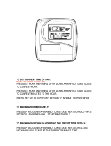
Programming Levels
There are 3 levels to the valve program. Master options and Factory options are typically adjusted at the facto-
ry. These options link the PCB function with the type of control valve and should not be tampered with. Ad-
vanced options are used to configure the unit when the valve is assembled to the tank so that it can function as
the proper size and intended system operation. Settings are the final options chosen when the unit is installed
to a specific location.
Button Configuration
Key Pad Configuration
MENU This function is to enter the basic set up information required at the time of installation.
SET This function is to accept the values if changed and advance to the next page in the menu.
+ / -
These buttons are used to increase or decrease the value of the settings while in the pro-
gramming mode.
Main Display Options
The main display page shows the Flow Rate, Date, Time Of Day, Remaining Volume, and Total Volume. The
display will alternate between the main page and the dealer information page.
PROGRAM LEVEL USER ACCESS
USER SETTINGS(I)
These settings are programmed when the unit is installed. The settings should only be adjusted by
a qualified person.
MAIN MENU (II)
These settings are programmed when the unit is installed. The settings should only be adjusted by
a qualified person.
ADVANCED MENU
(II)
These settings are programmed by the factory and should be adjusted when the valve is assem-
bled into a unit or system. It contains important settings so the valve will operate properly for the
type of system it is intended for. The settings should only be changed by qualified person.
HISTORY MENU (IV)
This menu contains key diagnostics for trouble shooting the system.
FACTORY MENU (V)
These settings are programmed by the factory. The settings are important for the operation of the
valve that should only be changed by a qualified person.
Flow Rate: 24.5 GPM
18-Apr-2015 10:35AM
Remain: 1,280 GAL
Capacity: 1,500 GAL
+
-
MENU
SET
Installation, Operation and Maintenance Manual
Models: XXX
/