Page is loading ...

Flexx Oxi-Gen Aeration Iron
and Sulfur Filter
081-FX-XXX

Table of Contents
Unpacking and Inspection ......................................................................................... 3
Safety Guide ...................................................................................................... 3
Before Starting Installation ........................................................................................ 4
Proper Installation .............................................................................................. 4
Tools, Pipe, Fittings, and Other Materials .......................................................... 4
About The System ..................................................................................................... 5
System Dimensions .................................................................................................. 6
Specifications ............................................................................................................ 7
How the Water System Works ................................................................................... 8
Where to Install the System ...................................................................................... 9
Preparation .............................................................................................................. 10
System Tank Preparation ................................................................................. 10
Media Installation ............................................................................................. 10
Installation Instructions ............................................................................................ 15
Programming Using Onboard Buttons .................................................................... 20
Master Programming Using Onboard Buttons ................................................. 21
Programming Using Water Logix App ..................................................................... 23
System Start-Up ...................................................................................................... 28
System Features ..................................................................................................... 29
Automatic Bypass During Regeneration ................................................................. 31
Power Head Exploded View .................................................................................... 32
Power Head Parts List ..................................................................................... 33
Valve Body Exploded View ...................................................................................... 34
Valve Body Parts List ....................................................................................... 35
Tank Assembly Exploded View ............................................................................... 36
Tank Assembly Parts List ................................................................................. 37
Bypass Exploded View / Parts List .......................................................................... 38
Troubleshooting ....................................................................................................... 39
Warranty .................................................................................................................. 40
Need help? 1.800.608.8792 2 www.uswatersystems.com

Unpacking and Inspection
Be sure to check the entire unit for any shipping damage or lost parts. Also note damage
to the shipping cartons. Contact US Water Systems at 1-800-608-8792 to report any ship-
ping damage within 24 hours of delivery. Claims made after 24 hours may not be honor-
ed. Small parts, needed to install the unit, will be in a parts bag. To avoid loss of the small
parts, keep them in the parts bag until you are ready to use them.
Safety Guide
For your safety, the information in this manual must be followed to minimize the risk of
electric shock, property damage or personal injury.
• Check and comply with provincial / state
and local codes. These codes must be
followed.
• Use care when handling the system. Do
not turn upside down, drop, drag or set
on sharp protrusions.
• The water system works on 12 volt-60 Hz
electrical power only. Be sure to use only
the included transformer.
• Transformer must be plugged into an in-
door 120 volt, grounded outlet only.
• WARNING: This system is not intended
for treating water that is micro biologically
unsafe or of unknown quality without ad-
equate disinfection before or after the
system. Contact US Water Systems for
disinfection treatment equipment.
Need help? 1.800.608.8792 3 www.uswatersystems.com

Before Starting Installation
Proper Installation
This water system must be properly installed and located in accordance with the Installa-
tion Instructions before it is used or the warranty will be void.
• Do not Install or store where it will be ex-
posed to temperatures below freezing or
exposed to any type of weather. Water
freezing in the system will break it. Do
not attempt to treat water over 100°F.
• Do not install in direct sunlight. Exces-
sive sun or heat may cause distortion or
other damage to non-metallic parts.
• Properly ground to conform with all gov-
erning codes and ordinances.
• Use only lead-free solder and flux for all
sweat-solder connections as required by
state and federal codes.
• Maximum allowable inlet water pressure
is 100 psi. If daytime pressure is over 80
psi, night time pressure may exceed the
maximum. Use a pressure reducing valve
(PRV) to reduce the pressure.
• Warning: Discard all unused parts and
packaging material after installation.
Small parts remaining after the installa-
tion could be a choke hazard.
Tools, Pipe, Fittings, and Other Materials
• Channel Locks
• Screwdriver
• Teflon Tape
• Razor Knife
• Two adjustable wrenches
• Additional tools may be required if modifi-
cation to home plumbing is required.
• To maintain full valve flow, be sure the
plumbing size matches the size of the
valve. The outlet pipe should be the
same size or larger than the water supply
pipe.
• Use copper, brass, or PEX pipe and fit-
tings. Some codes may also allow PVC
Plastic pipe.
• ALWAYS install the included bypass
valve or install a 3 shut-off valve hard pi-
ped bypass. Bypass valves allow the wa-
ter to be turned off to the system but can
still provide water to the house for water
use during repairs or service.
• 5/8" OD, 1/2" ID drain line is needed for
the valve drain.
Need help? 1.800.608.8792 4 www.uswatersystems.com

About The System
The Flexx Oxi-gen uses the air we breath to naturally reduce the effects of Iron, Manga-
nese, and Sulfur Gas. By introducing oxygen to the water, contaminants chemically
change to a physical particle that can be mechanically filtered out of this water. This natu-
ral process, called oxidation, is usually accomplished in other systems by using chemi-
cals such as H2O2 or potassium permanganate. Since the Flexx Oxi-gen does not use
chemicals to treat the water, maintenance and chemical byproducts associated with these
types of systems are eliminated. The energy required to operate this system is provided
by using extra power that is available in your well pump to inject free air into the water.
There are several normal side effects that may or may not occur when water is treated in
this manner:
• Cloudy or milky appearance to the treated water - This side effect is usually more
pronounced when the iron, manganese, or sulfur gas levels are low. Since the Flexx
Oxi-gen uses oxygen for the treatment of these contaminants, it can be expected to
have some amount left over in the treated water. The higher the contamination levels
are, the less oxygen there will be. It is the oxygen that gives the cloudy or milky ap-
pearance. Once the faucet is opened and the water is drawn, pressure is released and
allows the oxygen to escape. This usually will take from a few seconds to a minute de-
pending on the amount of oxygen and the pressure. This noticeable side effect tells
you the system is working properly and also will enhance the palatability of the water.
It's oxygen that gives water its fresh, crisp taste.
• Sputtering or slight coughing from the hot water side faucets - This is a normal
phenomenon that usually occurs first thing in the morning. As the highly oxygenated
Flexx Oxi-gen water is exposed to heat in the hot water tank, a small amount of oxygen
will separate. The longer the water is allowed to sit in the hot water tank, the more this
will be noticed.
Usually, this will only occur if the hot water is allowed to sit idle for eight (8) hours or
more. Consequently, when hot water is drawn after an extended period of no water
use, a slight sputtering or coughing may be experienced for a few seconds. If this cau-
ses the hot water to splash out of the sink, the problem is reduced by simply turning on
the cold water first and blending in the hot for several seconds. If there is a large
amount of free air noticed on the cold water side, there is a possible malfunction of the
system and US Water Systems should be contacted to service the unit.
Need help? 1.800.608.8792 5 www.uswatersystems.com

System Dimensions
Model Tank Size A B C D
FX-150 10" x 54" 61" 52" 10" 21"
FX-250 13" x 54" 61" 52" 13" 24"
Need help? 1.800.608.8792 6 www.uswatersystems.com

Specifications
Please review operating pressures, temperatures and water chemistry limitations to en-
sure compatibility.
Model Number FX-150 FX-250
Tank Size 10" x 54" 13" x 54"
Capacity (cu/ft) 1.5 2.5
Gravel Under-bedding 15 lbs. 25 lbs.
Backwash Flow Control (GPM) 5.0 7.0
Service Flow Rates 7 GPM 15 GPM
Peak Flow Rates 10 GPM 20 GPM
Pressure Drop @ Service Flow 5-7 PSI
Pressure Drop @ Peak Flow 15-20 PSI
Water Pressure 20 PSI Min / 100 PSI Max
Water Temperature 39°F Min / 100°F Max
Plumbing Connections 3/4" or 1" MPT
Electrical Requirements 100-240V, 50/60 Hz, 0.3 A / Output 12V, 500mA
Iron ≤ 12 ppm
Hydrogen Sulfide ≤ 20 ppm
Manganese ≤ 0.7 ppm
pH 6 - 9
Need help? 1.800.608.8792 7 www.uswatersystems.com

How the Water System Works
• Air is injected into the top of the tank, converting ferrous iron to ferric iron and oxidizing
sulfur after untreated water has passed through the control valve, preventing the con-
trol valve from fouling with iron and/or sulfur. The sludge that forms in most Air Injection
systems is simply gone and the iron and sulfur is eradicated with ease.
• Water Logix App and meter control give you total and advanced control over system
regeneration, efficiency, and ease of operation. All it takes is 30 seconds to program
the Flexx Oxi-gen.
• Simple 9 volt battery back-up keeps electronic motor active and will return the control
valve to service position in case of power failure during regeneration.
• Includes meter to provide water usage history.
• Air draw cycle can be initiated without a backwash cycle, saving 1000's of gallons of
water annually.
• The control valve slowly releases compressed air charge prior to backwash cycle, elim-
inating the explosive blast that can dislodge the drain line.
• Fully adjustable cycle times.
• Built-in bypass valve
NSF Approved Components - The US Water Systems Flexx Oxi-gen Aeration Iron and
Sulfur Filter is a fully automatic backwashing filtration system. It uses all NSF and FDA
approved components, including the Catalytic Carbon filter media, which is tested and
certified by the WQA to NSF/ANSI 61.
Water Logix App
• Communicates with your smartphone via Bluetooth
• Simply set the time of day, time of regeneration, and backwash frequency
• Uses a 9 volt battery so that, if power goes out during regeneration, it automatically re-
turns to service so as not to continually waste water to the drain.
• Monitors remaining battery life
• Fully programmable cycles
• Can be "precision tuned"
Need help? 1.800.608.8792 8 www.uswatersystems.com

Where to Install the System
• Place the system as close as possible to
the pressure tank (well system) or water
meter (city water).
• Place the system as close as possible to
a floor drain or other acceptable drain
point (laundry tub, sump, standpipe, etc)
• Connect the unit to the water system BE-
FORE the water heater (10' or more). DO
NOT RUN HOT WATER THROUGH THE
SYSTEM. Temperature of water passing
through the system must be less than
100°F.
• Do not install the system in a place
where it could freeze. Damage caused
by freezing is not covered by the war-
ranty.
• Put the system in a place where water
damage is least likely to occur if a leak
develops. The manufacturer will not re-
pair or pay for water damage.
• A 120 volt electric outlet is needed within
6 ft of the system. The transformer has
an attached 6 foot power cable. Be sure
the electrical outlet and transformer
are in an inside location so they are
protected from wet weather.
• If installing in an outside location, you
must take the steps necessary to ensure
the system, installation plumbing, wiring,
etc are protected from the elements and
contamination sources.
• Keep the system out of direct sun-
light. The suns heat may soften and dis-
tort plastic parts.
Need help? 1.800.608.8792 9 www.uswatersystems.com


4. Use the blue funnel provided to pour the gravel and carbon into the tank. Pour it
evenly around the hole to ensure it is well distributed in the tank and pour slow
enough to keep from plugging the hole. A helper may be needed to hold the funnel
during the filling process. The gravel is poured in first and the carbon second. Install
all the gravel and carbon that was sent. US Water Systems does NOT send extra
media. NOTE: It is recommended that a dust mask and safety goggles be worn to
prevent possible injury.
5. When the media is installed, move the tank side to side to settle the media. Remove
the funnel and clear cap from the distributor tube. Now install the Ferric iron collec-
tion spheres. Install all the spheres in the tank. Fill the tank with water and allow it to
soak for at least an hour before startup. Re-install the threaded plastic cap on the
tank.
Need help? 1.800.608.8792 11 www.uswatersystems.com

6. Lubricate the distributor O-rings on the valve connectors.
Need help? 1.800.608.8792 12 www.uswatersystems.com


8. Install the valve fastening bolt in the bottom of the valve through the support arm
bracket. Push the plastic air tube in the fitting on the side of the valve.
Need help? 1.800.608.8792 14 www.uswatersystems.com

Installation Instructions
1. If your hot water tank is electric, turn off the power to it to avoid damage to the ele-
ment in the tank.
2. If you have a private well, turn the power off to the pump and then shut off the main
water shut off valve. If you have municipal water, simply shut off the main valve. Go
to a faucet or spigot (preferably on the lowest floor of the house) and turn on the cold
water until all pressure is relieved and the flow of water stops.
3. Locate the media tank close to a drain where the system will be installed. The sur-
face should be clean and level.
NOTE: Any solder joints being soldered near the valve must be done before con-
necting any piping to the valve. Always leave at least 6" (152 mm) between the con-
trol valve and joints being soldered when soldering pipes that are connected to the
valve. Failure to do this could cause damage to the valve.
The system is equipped with male pipe threaded ports on the control valve bypass.
The bypass is marked with arrows to show proper flow direction. The arrow pointing
toward the valve indicates the inlet. The arrow pointing away from the valve is the
outlet.
Need help? 1.800.608.8792 15 www.uswatersystems.com

4. Insert the provided plumbing fittings into the bypass. 3/4" and 1" male pipe thread fit-
tings are supplied so ensure you pick the correct one for your plumbing. Tighten the
retaining nuts hand tight, ensuring that the fittings are not cross threaded.
Need help? 1.800.608.8792 16 www.uswatersystems.com

5. Be sure to use Teflon tape or other pipe sealant on the plumbing fitting threads and
install them in the bypass accordingly. Use an adjustable wrench to ensure they are
tight.
NOTE: All piping should be secured to prevent stress on the bypass valve and
connectors.
NOTE: Connections above are made using a stainless steel flex connector with
a rubber gasket and do not require Teflon tape.
Need help? 1.800.608.8792 17 www.uswatersystems.com


7. Turn both bypass handles perpendicular to the bypass to place the unit in the bypass
position. Slowly turn on the main water supply. At the nearest cold treated faucet or
spigot, open the faucet and let water run a few minutes or until the system is free of
any air or foreign material resulting from the plumbing work. If a faucet is used, make
sure the screen is removed first.
8. Make sure there are no leaks in the plumbing system before proceeding. Close the
water tap when the water runs clean. Check for leaks again.
9. Proceed to programming then to the start up instructions.
NOTE: The unit is not ready for service until you complete the start-up instruc-
tions. Be sure to program the unit first.
Need help? 1.800.608.8792 19 www.uswatersystems.com

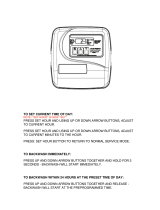
Programming Using Onboard Buttons
Plug the transformer into the port marked "P" on the valve. The LED screen will be flash-
ing between the time of day and the number of days between backwash cycles.
NOTE: The unit will recharge with air every night. The days between a full back-
wash cycle are what the flashing number represents.
1. To enter the Main Menu, press the Menu/Enter button. (Time of Day will flash)
2. To set the Time of Day, press the Set/Change button. (First digit will flash)
• To change digit value, press the Set/Change button.
• To accept the digit value, press the Menu/Enter button.
• Next digit will flash to begin setting.
• Once the last digit display is accepted, all digits will flash.
3. To set A.M. or P.M., press the Menu/Enter button.
• To change digit value, press the Set/Change button.
• To accept the digit value, press the Menu/Enter button.
• Once A.M. or P.M. is accepted, the next menu item will flash.
4. Days Between Backwash
• Press Menu/Enter button. This display is used to set the maximum amount of time
(in days) the unit can be in service without a backwash. This option setting is iden-
tified by the letter "A" in the left digit. Backwash will begin at the set Backwash
time. A "00" setting will cancel this feature. The max value for this setting is 29.
• To adjust this value, press the Set/Change button.
• To accept the digit value, press the Menu/Enter button.
Need help? 1.800.608.8792 20 www.uswatersystems.com
/