Page is loading ...

Tier1 Technical Support:
1-855-378-9116
Owners Manual
Air Induction Oxidation Filter
WH-IRN-MG-SLFR-BW-1054
1. Read all instructions carefully before operation.
2. Avoid pinched o-rings during installation by applying NSF certified lubricant to all seals (provided with install
kit).
3. This system is not intended for treating water that is microbiologically unsafe or of unknown quality without
adequate disinfection before or after the system.
CAUTION!
The unit should be
depressurized before
installing or replacing media

Table of Contents

3
Table of Contents
4
5
6
7
8
9
10
12
READ THIS PAGE FIRST
BEFORE STARTING INSTALLATION
SPECIFICATION
S
SULFIDE LIFE EXPECTANCY
CONTAMINANTS FOUND IN WATER
INSTALLATION
UNPACKING / INSPECTION
BEFORE INSTALLATION
PREPARATIONS
FILTER INSTALLATION
OPERATION
STARTUP INSTRUCTIONS
MAINTENANCE INSTRUCTIONS
16
BACKWASHING INSTRUCTIONS
17
18
19
20
21
CARE
CLEAN INJECTOR ASSEMBLY / PISTON AND/OR BRINE VALVE ASSEMBLY
PARTS BREAKDOWN
TROUBLE SHOOTING GUIDE
MASTER PROGRAMMING GUIDE
13

4
Read this manual thoroughly to become familiar with the
device and its capabilities before installing or operating your
Water Filter. Failure to follow instructions in this manual
could result in personal injury or property damage. This
manual will also help you to get the most out of your filter.
This system is intended for use on municipal water only and
its installation must comply with all State, provincial or local
regulations. Check with your local public works department
for plumbing and sanitation codes. In the event the codes
conflict with any content in this manual the local codes
should be followed. Consult your licensed plumber for
installation of this system.
This water filter is designed to operate on pressures of 30 psi
to 125 psi. If the water pressure is higher than the maximum
use a pressure reducing valve in the water supply line to the
filter.
This unit is capable of operating at temperatures between
40°F and 110°F (4°C - 43°C). Do not use this water filter on hot
water supplies.
Do not install this unit where it may be exposed to wet
weather, direct sunlight, or temperatures outside of the
range specified above.
Avoid pinched o-rings during installation by applying
(provided with install kit) NSF certified lubricant to all seals.
Filters are commonly exposed to high levels of iron,
manganese, sulfur, and sediments. Damage to pistons, seals,
and or spacers within the control valve are not covered in
this warranty due to the harsh environment.
It is recommended to regularly inspect and service the
control valve on an annual basis. Cleaning and or replacement
of piston, seals, and or spacers may be necessary depending
on how harsh the conditions are. An Annual Maintenance kit
(Part # 60010564) is available for this purpose.
Do not use water that is microbiologically unsafe without
adequate disinfection before or after this system.
This publication is based on information available when
approved for printing. Continuing design refinement could
cause changes that may not be included in this publication.
The manufacturer reserves the right to change the
specifications referred to in this literature at any time,
without prior notice.
READ THIS PAGE FIRST
BEFORE STARTING INSTALLATION
INSTALL NOTES &
SAFETY MESSAGES
Watch for the following
messages in this manual:
NOTE
Do not remove or destroy
the serial number. It must be
referenced on request
for warranty repair or
replacement
CAUTION!
Disassembly while
under pressure can
result in flooding.
WARNING!
ELECTRICAL SHOCK
HAZARD! UNPLUG THE UNIT
BEFORE REMOVING THE
COVER OR ACCESSING ANY
INTERNAL CONTROL PARTS
NOTE: used to emphasize
installation, operation or
maintenance information
which is important but does
not present a hazard.
CAUTION: used when
failure to follow directions
could result in damage to
equipment or property.
WARNING: used to
indicate a hazard which
could cause injury or death if
ignored.

4 5
Model
Media
Cu Ft
Flow Rate USGPM
Mineral Tank
Size
Pipe Size
Inches
Ship
Weight Lbs
Service Peak Backwash
AIOB150 1.5 4 10 5 10 x 54 3/4” - 1” 101
Water and Time Consumed During Regeneration
Model
Backwash
Minutes
Rapid Rinse
Minutes
Air Draw
Minutes
Total Time of
Regeneration
Total Water
Consumed During
Regeneration (GAL)
AIO150 15 0 45 60 80
SPECIFICATIONS
Working Temperature = 34-110°F (1-43°C)
(Do not subject the unit to freezing temperatures)
Working Pressure = 30-125 PSIG (137-861 kPa)
Voltage = 120V / 60 Hz
Pipe Size = 3/4” and 1”
• At the stated service flow rates, the pressure drop
through these devices will not exceed 15 psig.
• The manufacturer reserves the right to make
product improvements which may deviate from the
specifications and descriptions stated herein, without
obligation to change previously manufactured products
or to note the change.
* Do not use water that is microbiologically unsafe
without adequate disinfection before or after the
system.
Peak flow rates intended for intermittent use only (10
minutes or less) and are for residential applications only.
Do not use peak flow rate for commercial applications
or for a continuous rate when treated water supplies are
geothermal heat pump, swimming pool, etc.
For satisfactory operation, the pumping rate of the
well system must equal or exceed indicated backwash
flow rate.
All units come with plastic bypass
Maximum Iron = 30.0ppm
Hydrogen Sulde = Trace and 5ppm for AIOC Filters
Manganese = 1.0 ppm
pH = 6.5 to 8.5
Media Loaded in 75,10 and 15 Models Only. Models
ending in ‘M’ are required when raw water has up to
1.0 mg/l of manganese or when pH is below 7.0. Over a
period of time, it may become
necessary to add more media to the unit. Adding media is
necessary only when water has low pH or manganese is
present. only
A
B
Models A (Inches) B (Inches)
150
61.5 10"
SYSTEM DIMENSIONS
HOW DOES THE CHEMICAL FREE AIO IRON FILTER WORK?
This filter works by adding oxygen to the incoming water by passing it through a bubble of compressed air. The water is then passed through a special filter bed.
The special media not only increases the pH of the water to enhance iron removal but also acts as a physical barrier to trap iron precipitate.
As more water passes through this iron filter, the oxygen in the unit is used up, and the media gets loaded with iron. The regeneration process then begins in order to replenish
the supply of oxygen, and to backwash the precipitated iron trapped in the media bed.
The iron removal efficiency will be
more effective with high pH water.
This media acts as a catalyst for the removal of iron and manganese from the water but require pre-oxidation. The water is pre-oxidized from the air bubble on the top of the tank and this media
removes the iron and manganese from the water. This is not recommended to remove hydrogen sulfide from the water and requires high pH water. The media is not sacrificial hence no
replenishment is required.

6
Step1 Step 2
Sulde (ppm) 25 GPD* 50 GPD* 100 GPD* 125 GPD* 150 GPD* 200 GPD* 250 GPD* 300 GPD*
0.5 31,623 15,811 7,906 6,325 5,270 3,953 3,126 2,635
1 15,811 7,906 3,953 3,126 2,635 1,976 1,581 1,318
1.5 10,541 5,270 2,635 2,108 1,757 1,318 1,054 878
2 7,906 3,953 1,976 1,581 1,318 988 791 659
2.5 6,325 3,162 1,581 1,265 1,054 791 632 527
3 5,270 2,635 1,318 1,054 878 659 527 439
3.5 4,518 2,259 1,129 904 753 565 452 376
4 3,953 1,976 988 791 659 494 395 329
4.5 3,514 1,757 878 703 586 439 351 293
5 3,162 1,581 791 632 527 395 316 264
5.5 2,875 1,437 719 575 479 359 287 240
6 2,635 1,318 659 527 439 329 264 220
* Gallons Per Day
To calculate bed life for carbon volumes other than 1 cu. ft. multiply value in table by actual carbon volume (in cu. Ft.). A minimum of 4 ppm of Dissolved Oxygen is required for
efficient removal for all sulfide concentrations listed above.
When removing Iron and Hydrogen Sulfide, dealers must compensate the additional load on the media by increasing bed size and backwash frequency.
Usage rates are based on a maximum total organic carbon (TOC) loading of 10 percent by weight. For higher loadings, the usage listed in the table will increase and bed life
and volume treated will decrease.
Sulfide problems in surface water sources are much less frequent because of the natural aeration that occurs in most flowing surface water sources. Aeration is the most
common treatment method in terms of volume of water treated annually because it’s inexpensive, easy to maintain and doesn’t produce potentially harmful reaction products
such as tri-halo-methanes (THMs).
Another method is the use of catalytic carbon to sulfide reduction through oxidation of sulfides with dissolved oxygen present in the water. Reduction of sulfides with catalytic
activated carbon first involves adsorption of the sulfide species and then catalytic oxidation. The dissolved oxygen (minimum required 4 ppm) reacts with sulfides and oxidizing
them to elementary sulfur and sulfates.
Our Hydrogen Sulfide reduction AIO filter combines aeration with catalytic carbon technology to effectively reduce sulfur from water. Following is the information on our AIO
Filter System for the reduction of sulfides from water.
Life Expectancy for media based on sulfide influent (Days for 1 cu. ft. unit)
Step1 Step 2
Step 3
Step 3
The application and system recommendation should be performed by an authorized dealer.
AIO Control Valve Regeneration Sequence
The regeneration cycle goes through 3 steps.
1. Backwash (minimum 30 psi inlet pressure required): During the backwash cycle, water
flows upwards through the bed, expanding the media and carrying any precipitated
contaminants trapped within it to the drain. The air is evacuated from the tank.
2. Air Draw: The air is injected to oxidize the tank. With the new design, the filter pulls the
air into the tank to perform the oxidation. The unit is replenished with a new bubble of air.
During this step water will run to the drain. There is a delay at the start of the cycle while the
pressure of the air within the tank reaches atmospheric pressure. During this time no air is
drawn into the tank. Once the pressure has equalized you can usually hear the sound of air
being drawn in to the unit.
3. In-Service Position: The unit then returns to the In-Service position. While this happens
water continues to enter the tank, compressing the air into a bubble in the top of the tank.
The actual size of the bubble will vary depending on the on-site conditions.
6

7
IRON (Fe)
Iron concentrations as low as 0.3 ppm will cause staining. The iron concentration, together with the flow rate demand and the consumption rate of the water determines the
basic size filter system. The higher these factors are, the larger the required system. The filter system is capable of filtering out the three main types of iron found in water
supplies: Soluble iron (also known as “clear water” or ferrous iron), precipitated iron (also known as “red water” or ferric iron) and bacterial iron (also known as iron bacteria).
There is no apparent upper limit of iron concentration for the filter, but special care must be taken when selecting a filter model if your water has a combination of high iron,
very low pH and/or manganese.
MANGANESE (Mn)
The presence of manganese can be bothersome, even for a chemical free iron filter. As little as 0.05 ppm of manganese can produce a brownish or black stain. The ability of the
filter to remove manganese depends on its concentration and the pH of the water.
Manganese tends to “coat” the filter media, rendering it incapable of increasing the pH, and therefore ineffective in removing either the iron or the manganese. Manganese,
however, will precipitate in the filter bed when the pH is increased. To accomplish this a special “MN” type media can be provided that contains additional quantities of the pH
raising component (“MN adder”). The use of “MN” type media is for applications where the manganese is not more than 1.5 ppm, and the pH is at least 6.5.
pH
The pH of water measures its acidity or its alkalinity. Water with a pH of less than 7.0 is acidic, above 7.0 it is alkaline, and a pH of 7.0 is neutral. The lower the pH value is
below 7.0 the greater the acidity, and the higher the pH value is above 7.0 the more alkaline. Acidic water (pH less than 7.0) is corrosive to pipes, appliances, etc. A pH of 7.0 or
higher facilitates iron removal — which is why the filter is designed to increase the pH when it is less than 7.0.
TANNINS (Humic Acid)
Tannins (also known as humic acid) which are present in some water supplies, are the result of decaying vegetable matter. If the tannin concentration is above approximately
0.5 ppm, it will form a sticky coating on the media, thus rendering it incapable of filtering the iron. A chemical free iron filter is not recommended under this condition. If the
tannin concentration is less than 0.5 ppm, a chemical free iron filter may be installed.
HYDROGEN SULFIDE (H2S)
Hydrogen sulphide (often referred to as “sulphur”), is easily detectable by its objectionable “rotten egg” odour. Sulphur corrodes iron, brass, copper and silver. A chemical free
iron filter is capable of removing sulphur in concentrations of up to 3 to 5 ppm. Whenever hydrogen sulphide is present, backwashing must be performed at more frequent
intervals.
CONTAMINANTS FOUND IN WATER

8
8
1. Control Valve
2. Tank
3. Parts Box
4. Owners Manual
5. Drain Hose & Clamp (Not included in some brands)
UNPACKING / INSPECTION
Be sure to check the entire unit for any shipping damage or parts loss. Also note damage to the shipping cartons. Contact the transportation company for all damage and loss
claims. The manufacturer is not responsible for damages in transit.
Small parts, needed to install the filter, are in a parts box. To avoid loss of the small parts, keep them in the parts bag until you are ready to use them.
What is included in the boxes?
1. Control Valve
2. Tank
Distributor
Tube Inside
the Tank
Media Inside
the Tank.
Brine Line Air
Check
18280
Upper Basket
3. Parts Box
60090003
2X 1” Straight
Adapter
60010006
Bypass Tool
60010026
O Rings Attached
60090010
2 X 3/4”
Elbow
Adapter)
60010630
Transformer
92360
Grease
Packet
1” Check Valve
There are 7 Red clips.
Please check to make
sure you have all of
them.
Control Valve

8QILOWHUHG:DWHU%\SDVV
/RRS&XW&DSSHG
*URXQG6WUDS5HTXLUHG%HFDXVH
RI%UHDNLQ&RQWLQXLW\
)LOWHUHG:DWHU/LQHLQ+RPH
Fig. 1.
BEFORE INSTALLATION
Make sure you have a copy of your most recent water test results. If your water has not been tested previously you can contact
your supplier of this product to obtain a water sample bottle to be sent to one of our facilities for a free analysis. It is important
that this product not be installed until you have this information.
In all cases where metal pipe was originally used and is later interrupted by poly pipe or the Noryl bypass valve or by physical
separation, an approved ground clamp with no less than #6 copper conductor must be used for continuity, to maintain proper
metallic pipe bonding.
Inspecting and Handling
Inspect the equipment for any shipping damage. If damaged, notify the transportation company and request a damage
inspection. Damage to cartons should also be noted.
Handle the filter unit with care. Damage can result if it is dropped or set on sharp, uneven projections on the floor.
Do not turn the filter unit upside down.
To Ensure this Product Functions Properly:
Your feed water line size to the unit must be a minimum of 3/4 inch with an operating pressure of no less than 30
psi
and no more than 125 psi.
MECHANICAL:
Do not use petroleum based lubricants such
as petroleum jelly, oils or hydrocarbon based lubricants. Use only 100% silicone
lubricants (grease packet provided in parts kit). All plastic connections should be hand tightened only. Teflon tape may be used
on connections that do not use an O-ring seal. Do not use pliers or pipe wrenches except where indicated by Nut shape (eg. pipe
adapters) All plumbing must be completed according to local codes. Soldering connections should be done before connecting
any pieces to the pipe as excessive heat can damage them.
Tools Required for Installation:
NOTE: We recommend installation only be completed by a competent installer or
plumbing professional to insure this product is installed in accordance with local
plumbing codes.
sTwo adjustable wrenches
sAdditional tools may be required if modification to home plumbing is required.
sPlastic inlet and outlet fittings are included with the filter. To maintain full valve flow, 3/4” or 1” pipes to and from the
filter fittings are recommended. You should maintain the same, or larger, pipe size as the water supply pipe, up to the filter
inlet and outlet.
sUse copper, brass, or PEX pipe and fittings.
sSome codes may also allow PVC plastic pipe.
sALWAYS install the included bypass valve, or 3 shut-off valves. Bypass valves let you turn off water to the filter for repairs if
needed, but still have water in the house pipes.
s5/8” OD drain line is needed for the valve drain. A 10’ length of hose is not included with some brands.
9
NOTE
All government codes and
regulations governing the
installation of these devices
must be observed.
NOTE
If a severe loss in water
pressure is observed when
the filter unit is initially
placed in service, the filter
tank may have been laid on
its side during transit. If this
occurs, backwash the filter
to “reclassify” the media.
*NOTE
Due to transportation
and climatic conditions all
connections including the
valve to the tank need to be
checked at time of
installation and tightened if
necessary.
NOTE
Check your local electrical
code for the correct clamp
and cable size.
CAUTION!
If the ground from the
electrical panel or breaker
box to the water meter or
underground copper pipe
is tied to the copper water
lines and these lines are cut
during installation of the No-
ryl bypass valve and/or poly
pipe, an approved grounding
strap must be used between
the two lines that have been
cut in order to maintain
continuity. The length of the
grounding strap will depend
upon the number of units
being installed and/or the
amount of copper pipe being
replaced with plastic pipe.
See Fig. 1.

14
PREPARATIONS
Water Lines
Outside faucets used to water lawns and gardens should not supply softened water. A new water line is often required to be connected to supply hard water to the inlet of
the water softener and to the outside faucets. Cut the water line between where it enters the house and before any lines that branch o to feed the hot water heater or
other xtures in the house and as near the desired location of the water softener as possible. Install a tee tting on the feed end of the cut pipe, and an elbow tting on the
other end. Install piping from the tee to the inlet of the water softener and from the elbow to the outlet of the softener. To sever the water lines which branch o to feed any
outside faucets, cut the branch lines approximately two inches from the tting on the main water line. Install an elbow on the end of the pipe nearest the outside faucet and
a cap on the end connected to the existing water line. Install piping from the tee installed on the inlet line to the water softener to the elbow installed on the pipe to the
outside faucet. Following this procedure will result in all lines in the house, with the exception of the outside faucets, but including the water heater and therefore the hot
10
water lines, being supplied with soft water.
Inlet
Outlet
Determine the best location for your water Softener, bearing in mind the location of your water supply lines,
drain line and 120 volt AC electrical outlet. Subjecting the Softener to freezing or temperatures above
43°C (110°F) will void the warranty.
INSTALLATION STEPS
Please notice the inlet and outlet
labels on the valve as shown here
to determine the position of the
equipment:
Facts to Remember When Planning Your Installation
1. All installation procedures must conform to local and state or provincial plumbing codes.
2. Outside faucets used to water lawns and gardens should not supply untreated water, replace untreated water with feed water
to the unit. If necessary to do this please install check valve, see page 14. A new water line is often required to be connected to
supply untreated water to the inlet of the water lter and to the outside faucets.
3. Make sure the bypass is attached well to the control valve. Connect the straight or elbow connectors to the bypass with red
clips. Connect the inlet and outlet of the water lter to the plumbing of the house. The control valve must not be submitted
to temperatures above 43°C (110°F). When sweat ttings are used, to avoid damaging the control valve, solder the threaded
copper adapters to the copper pipe and then, using Teon tape, screw the assembly into the bypass valve.
Do not use pipe thread compound as it may attack the material in the valve body.
4. Apply Teon Tape and Orings to the ttings
5. Connect Filter to the house plumbing. Any solder joints near the valve must be done before connecting any piping to the valve.
Always leave at least 6” (152 mm) between the valve and joints when soldering pipes that are connected to the valve. Failure to
do this could cause damage to the valve.
6. Drain Line connection: Using Teon tape, screw the 1/2” hose barb and attach oring into the drain port in the valve. Attach
1/2” drain hose (Supplied with some models and brands) to the hose barb and tighten securely with a hose clamp (Supplied
with some models and brands). Run the drain line to a oor drain or a laundry drain. Complete any necessary plumbing.
7. Using the Allen Key (included), place the unit in the bypass position. Slowly turn on the main water supply. At the nearest cold
treated water tap nearby remove the faucet screen, open the faucet and let water run a few minutes or until the system is free
of any air or foreign material resulting from the plumbing work.
8. Make sure there are no leaks in the plumbing system before proceeding. Close the water tap when water runs clean.
9. Open the brine tank / cabinet salt lid and add water until there is approximately 3” (75 mm) of water in the tank. Do not add
salt to the brine tank at this time.

11
NOTE
Inspect and check that the
brine line air check assembly
is connected to the valve.
NOTE
Ensure that the brass and
plastic nut connected to the
air check assembly is tight.
Make sure both brass and
plastic nuts are tightened well
There are 7 Red clips.
Please check to make
sure you have all of
them.
Make sure the bypass is attached well to the control valve. Connect the straight or elbow connectors to the bypass
with red clips. Connect the inlet and outlet of the water lter to the plumbing of the house. The control valve must
not be submitted to temperatures above 43°C (110°F). When sweat ttings are used, to avoid damaging the control
valve, solder the threaded copper adapters to the copper pipe and then, using Teon tape, screw the assembly into the
bypass valve.
Do not use pipe thread compound as it may attack the material in the valve body.
Drain Line connection: Using Teon tape, screw the 1/2” hose barb and attach oring into the
drain port in the valve. Attach 1/2” drain hose (Supplied with some models and brands) to the
hose barb and tighten securely with a hose clamp (Supplied with some models and brands).
Run the drain line to a oor drain or a laundry drain. Complete any necessary plumbing.
Drain Line Connection

16
12
5
Outlet
Inlet
NOTICE - THERE ARE RAISED
ARROWS ON THE BYPASS
ASSEMBLY INDICATING
DIRECTION OF WATER FLOW
Inlet
*Check Valve
Outlet
*NOTE
Check local plumbing codes
in regards to requirements
for use of Check Valve or
back flow prevention or
vacuum breaker
Cold (Raw water)
Cold (Filtered water)
Cold (Raw water
)
*Check Valve
Water Heater
Hot (Soft Water)
Water Softener
AIO
Filter
InIn Ou
tI
nOut
Out
Cold (Soft Water)
T
o Outside Faucet
Connect Filter to the house plumbing. Any solder joints near the valve must be done before connecting any piping to the valve. Always leave at least 6” (152 mm) between
the valve and joints when soldering pipes that are connected to the valve. Failure to do this could cause damage to the valve.
Correct Installation of the Check Valve: Install 1” check valve on inlet of bypass valve. The check valve needs to be installed at the highest possible level of the plumbing line to
avoid air trap. Please see an example below:
CAUTION!
Never insert drain line
directly into a drain, sewer line, or trap.
Always allow an air gap between the drain
line and the wastewater to prevent the
possibility of sewage being back-siphoned
into the conditioner.
NOTE
Waste connections or drain
outlet shall be designed and
constructed to provide for
connection to the sanitary
waste system through an
air-gap of 2 pipe diameters
or 1 inch (22 mm) whichever
is larger.
FILTER INSTALLATION

13
TIME
05:22 PM
Sample
Connection
Sample
Connection
SERVICE
BYPASS
Sample
Connection
Sample
Connection
SERVICE
BYPASS
MANUAL REGEN
Delay Immediate
BACKWASH
IIIIIIIIIIIIIIIIIIIIIIII 15 Minutes
BRINE DRAW
IIIIIIIIIIIIIIIIIIIIIIIIIIIIIIIIIIIIIIIIIIIIIIII 50 Minutes
BACKWASH
BRINE DRAW
RINSE (SKIP)
REFILL (SKIP)
Regen Sequence - Once in Regeneration, the cycle can be skipped by pressing any button.
The controller will show the
following on the screen - Time,
Date and number of Days
Remaining for Regeneration.
STARTUP INSTRUCTIONS
1. Connect the Transformer to the Valve
Plug the 12-volt transformer into a 120 VAC 60 Hz outlet.
Familiarize with Button Configuration:
2. Screen Display
3. Manually Regenerate the Valve
Manually index the valve with the control knob to BA.WA. or press SET
and hold display will come up showing
delay ashing press Up and Down Arrows to immediat e and press MENU to initiate a manual
regeneration. Once the valve is in the Backwash position please unplug.
This function is to accept the values if changed and advance to the next page in
the menu.
These buttons are used to increase or decrease the value of the settings while in
the programming mode.
This function is to enter the basic set up information required at the time of
installation.
Key Pad Configuration:

18
14
SERV.
Service
BRINE RINSE REFILL
BA.WA.
BACKWASH
4. Manual Regeneration
To start an immediate regeneration turn the knob clockwise from the service position (9:00) to the 10:00 position. Within a few seconds the an immediate regeneration will
begin. Using the knob you can manually advance to the next position. Pressing any button will also advance to the next position.
For Delayed Regeneration, Press SET Button Once

15
STARTUP INSTRUCTIONS (CONTINUED)
4. Manually Regenerate the Valve (Continued)
CALENDAR
CLOCK
TIME
10:15 AM
REMAIN
DAYS 03
TIME
10:15 AM
REMAIN
GAL 1075
TIME
10:15 AM
REMAIN
GAL 1075
TIME
10:15 AM
REMAIN
DAYS 03
REMAIN
GAL 1075
METER
IMMEDIATE
METER
DELAYED
METER
OVERRIDE
MAIN DISPLAY OPTIONS
The main display page according to the regeneration mode setting. The display will alternate between the time of day, remaining
gallons, and remaining days..
Key Pad Conguration:
4a. Open the inlet on the bypass valve slowly and allow water to enter the unit. (The outlet of the bypass should remain closed to prevent any nes or debris from entering the
plumbing system. Allow all air to escape from the unit before turning the water on fully then allow water to run until the drain water appears to be clear of any nes or color.
4b. Plug in the valve. Allow the valve to continue its cycles until complete and back in service. Do not manually shorten this cycle as it is critical to have the valve go through all
cycles normally to purge all air from the control valve for the upow injection system to work correctly.
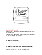
4c. The Valve is already programmed from factory. Please set up date and time of day and and days between regenerations.
Press MENU key
to advance to TIME OF DAY. TIME OF DAY will ash.
Press the Up and Down keys
to adjust the TIME OF DAY . Press & hold he Up and Down keys
to quickly advance the hour & minutes. When
desired time is displayed press SET
to advance to the HARDNESS setting. HARDNESS will ash.
Press the Up and Down keys
to adjust the HARDNESS (Min 1/Max 199). When desired hardness is displayed press SET
to advance to the PEOPLE
setting (Min 1/Max 9). PEOPLE will ash.
When desired number of people is displayed press SET
to complete programming.
NOTE** All units are factory programmed for the correct size and regeneration cycle, alteration should only be done by a factory
trained technician or after consultation with one of our technical representatives if you have any questions please
call: 1-855-378-9116
This function is to accept the values if changed and advance to the next page in
the menu.
These buttons are used to increase or decrease the value of the settings while in
the programming mode.
This function is to enter the basic set up information required at the time of
installation.
Key Pad Configuration:

20
16
1. Verify the pumping rate of the system - do not refer to a pumping curve for this data. Follow the instructions found on page 7. If the measured pumping rate is less than the
backwash rate of the lter, see page 39, Trouble Shooting.
2. Have your water tested - for pH, iron and manganese on both the treated and raw water to ensure your water conditions haven’t changed.
3. Inspect the Control Valve and the piping between the iron lter and the pressure tank to ensure they are not plugged with raw iron. If the line becomes plugged, the ow of water
to the home will be reduced. This will result in a reduction of water available for backwashing the unit which will inhibit operation of the system.
4. Air-to-water pressure tank - periodically drain and ush your tank to prevent a build-up of precipitated iron from forming in the bottom of the tank.
5. Bladder tank - periodically check that the bladder air pressure remains at 2 psi lower than the cut-in pressure of your pump.
6. For applications with low pH, manganese or hydrogen sulde, consult your local dealer for specic instructions to maintain the eciency and operation of your lter.
7. Periodic cleaning of the air vent assembly with mild acid or vinegar will ensure that it continues to vent excess air properly.
8. The lter tank can be cleaned with a mild soap solution.
9. Never subject the unit to freezing
Care of Your Filter
To retain the attractive appearance of your new water filter, clean occasionally with a mild soap solution. Do not use abrasive cleaners, ammonia or solvents. Never subject your
filter to freezing or to temperatures above 43°C (110°F).
Servicing Components
The seals and cartridge should be inspected and cleaned , depending on the inlet water quality and water usage.
MAINTENANCE INSTRUCTIONS
Your iron filter requires some minor maintenance to ensure optimum performance and years of trouble-free clean water. The following steps should be performed once or twice a
year (more often under harsh conditions):

17
PEOPLE
IN
FAMILY
IRON CONTENT (PPM)
2 4 6 8 10 12 14 16 18 20
1 1 1 1 1 1 1 1 1 1 1
2 1 1 1 1 1 2 2 2 2 2
3 1 1 1 2 2 2 3 3 3 3
4 1 1 2 2 2 3 3 4 4 4
5 1 1 2 2 3 3 4 4 6 6
6 1 2 2 3 3 4 6 6 6 6
To Calculate Backwash Frequency - Special Applications
To ensure adequate reserve capacity and prevent loss of water pressure between backwashes the gure of 15,000 (not the full 30,000 ppm capacity) is used to calculate backwash
frequency. Determine your backwash frequency as follows:
1. Estimate daily iron removal requirements using the following calculation:
No. of people in family
x 75 gallons of water per person
+ No. of gallons of water for special use
= No. of gallons of water required per day
x Iron concentration (ppm)
= Daily iron removal requirements (ppm)
2. Establish backwash frequency using daily iron removal requirements to complete the following calculation:
15,000 iron removal capacity (ppm)
÷ Daily iron removal requirements (ppm)
= No. of backwashes required in 12 day schedule
Example: You have four in the family, 8 ppm of iron and a swimming pool requiring 46 gallons of water per day.
4 People in the family
x 75 Gallons of water per person
300 Gallons of water for family
+ 46 Gallons of water for the pool
346 Gallons of water required per day
x 8 Iron concentration
2,768 Daily iron removal requirements (ppm)
1 5,000 Iron removal capacity (ppm)
÷ 2,768 Daily iron removal requirements (ppm)
5.4 Backwash frequency (days)
The calculation indicates the need to backwash every 5.4 days. The control can only be programmed to backwash at intervals of two, three, four, six and twelve days. The control
would be programmed to the closest more frequent setting i.e. every four days.
1.
Locate the box intersected by the number of people in your family and
the parts per million (ppm) of iron in your water (if your ppm is
between two numbers on the guide, use the higher number).
2. The number in the box represents how many times your lter has to
backwash in a twelve day schedule.
Backwash frequency for households with average water use can be determined using the following guide. The guide cannot be used if the ltered water supplies a swimming
pool, geothermal pump, outside spigots or other high water demand devices or activities. If your application includes any of the foregoing refer to the paragraph on “Special
Applications” below:

3.
2.
4.
1.
18
CLEAN INJECTOR ASSEMBLY
1. Remove two screws of the injector cap.
2. Pull the Injector Cap Out
3. Remove the injector assembly, oring and screen
4. Clean the injectors and replace cap

28
1” Check Valve
Control Valve
Distributor
Upper Diffuser
Check Valve
Bypass
19
PARTS BREAKDOWN

32
20
TROUBLE SHOOTING GUIDE
1. Water is clear when drawn, turns red upon standing (stain producing)
a) Insucient air drawn by the valve- Check Air Draw time
b) Bypass open or leaking - Close bypass valve and/or repair as necessary
c) Filter bed backwashed at improper intervals - Refer to backwash frequency chart in operation manual to ensure unit is set correctly
d) Do not increase the backwash frequency unless required to based on the chart, since the media needsto be some what iron-fouled for best
performance (in more severe iron-fouling cases, lter bed may need chemicalcleaning — contact dealer)
e) Presence of manganese or tannins - Recheck water analysis
f) Loss of air pocket in unit - generally caused by the check valve failing - clean and or replace the check valve
2. Water is red when drawn from tap
a) Filter bed overloaded with precipitated iron due to insucient backwash ow rate - causing channelling a) Recheck well pumping rate and correct as required
b) Check for obstructions or kink in drain line, or for improper drain line ow controller (see specs). Upon correction of this problem, if manually backwashing does not clear bed
of iron, lter bed may need chemical cleaning
c) Filter bed backwashed at improper intervals - Refer to backwash frequency chart in operation manual to ensure unit is set correctly. Do not
increase the backwash frequency unless required to based on the chart, since the media needs to be somewhat iron-fouled for best performance (in more severe iron-fouling
cases, lter bed may need chemical cleaning — contact dealer)
3. Excessive pressure loss through lter
a) Filter bed overloaded with precipitated iron - Refer to Section 2 above
b) Control inlet/outlet valve(s) not fully open - open valves
c) Sand, silt or mud collecting in lter media - check well for these conditions
d) Filter bed not properly “classied” - Manually backwash to reclassify
e) “Cementing” or “channelling” of lter media - Prod (stir) lter bed to break up hardened layer, backwash frequency to prevent recurrence increase
f) Pipes from pump or pressure tank to lter are clogged or restricted - clean or replace as required then refer to section 2 above
4. “MILKY” OR “BUBBLY” WATER (APPEARS TO CONTAIN SMALL BUBBLES)
a) Excess air-draw - Check adjustment for duration of draw in “Air Draw” cycle
b) Excess gases in water (carbon dioxide, hydrogen sulde, methane) - May require cleaning or installation or air-reliefcontrol (contact dealer)
c) Excessive ow rate through the unit - refer to specications for the unit do not exceed recommended service ow rates restrict manually with a valve or contact dealer for a
ow controller.
5. Valve not drawing air
a) Check direction of brine line check valve. The arrow on the check valve should be towards the valve
b) Check Programming
c) Check Valve Inlet and Outlet direction. Looking at the control valve from the front, the water should enter the valve from left hand side
d) Check the brass nut of the brine line assembly is not loose
/