Page is loading ...

Matrixx Greensand Plus Iron
Filtration System
081-MXF-GS-XXX

Table of Contents
Unpacking and Inspection ......................................................................................... 3
Safety Guide ...................................................................................................... 3
Before Starting Installation ........................................................................................ 4
Proper Installation .............................................................................................. 4
Tools, Pipe, Fittings, and Other Materials .......................................................... 4
System Dimensions .................................................................................................. 5
Backwashing Filter Introduction ................................................................................ 6
Where to Install the System ...................................................................................... 7
Water Meter Installation Instructions ......................................................................... 8
Chemical Solution Tank (With Pump) Installation Instructions ................................. 11
Chemical Pump Wiring Installation Instructions ............................................... 15
Retention Tank Installation ...................................................................................... 17
Preparation .............................................................................................................. 18
Filter Tank Preparation ..................................................................................... 18
Media Installation ............................................................................................. 18
Installation Instructions ............................................................................................ 22
Chemical Injection Pump Start-up Instructions ....................................................... 26
System Regeneration .............................................................................................. 27
Normal Operation ............................................................................................. 27
Starting a Regeneration Cycle ......................................................................... 27
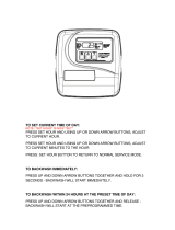
Programming Using Onboard Buttons .................................................................... 28
Programming Using Water Logix App ..................................................................... 29
Automatic Bypass During Regeneration ................................................................. 34
System Start Up ...................................................................................................... 35
Chlorine Injection Setting ........................................................................................ 36
Features .................................................................................................................. 37
What to Expect ........................................................................................................ 39
Routine Maintenance .............................................................................................. 40
Maintenance Schedule .................................................................................... 40
Power Head Exploded View / Parts List .................................................................. 41
Bypass Exploded View / Parts List .......................................................................... 42
Valve Body Exploded View / Parts List .................................................................... 43
Warranty .................................................................................................................. 44
Need help? 1.800.608.8792 2 www.uswatersystems.com

Unpacking and Inspection
Be sure to check the entire unit for any shipping damage or lost parts. Also note damage
to the shipping cartons. Contact US Water Systems at 1-800-608-8792 to report any ship-
ping damage within 24 hours of delivery. Claims made after 24 hours may not be honor-
ed. Small parts, needed to install the unit, will be in a parts bag. To avoid loss of the small
parts, keep them in the parts bag until you are ready to use them.
Safety Guide
• Check and comply with your provincial / state and local codes. You must follow these
guidelines
• Use care when handling the system. Do not turn upside down, drop, drag, or set on
sharp protrusions
• The water treatment system works on 120 volt-60 Hz electrical power only. Be sure to
use only the included transformers.
• Transformer must be plugged into an indoor 120 volt, grounded outlet only.
• Be sure to keep chlorine and other chemicals out of the reach of children.
• Keep the lid for the chlorine solution tank in place.
• DO NOT inhale air from the solution tank.
Need help? 1.800.608.8792 3 www.uswatersystems.com

Before Starting Installation
Proper Installation
This water treatment system must be properly installed and located in accordance with
the Installation Instructions before it is used or the warranty will be void.
• Do not Install or store where it will be ex-
posed to temperatures below freezing or
exposed to any type of weather. Water
freezing in the system will break it. Do
not attempt to treat water over 100°F.
• Do not install in direct sunlight. Exces-
sive sun or heat may cause distortion or
other damage to non-metallic parts.
• Properly ground to conform with all gov-
erning codes and ordinances.
• Use only lead-free solder and flux for all
sweat-solder connections as required by
state and federal codes.
• Maximum allowable inlet water pressure
is 100 psi. If daytime pressure is over 80
psi, night time pressure may exceed the
maximum. Use a pressure reducing valve
(PRV) to reduce the pressure.
• Warning: Discard all unused parts and
packaging material after installation.
Small parts remaining after the installa-
tion could be a choke hazard.
• Periodic control testing for the contami-
nant being treated is recommended to
ensure system performance.
Tools, Pipe, Fittings, and Other Materials
• Channel Locks
• Screwdriver
• Teflon Tape
• Razor Knife
• Two adjustable wrenches
• Additional tools may be required if modifi-
cation to home plumbing is required.
• To maintain full valve flow, be sure the
plumbing size matches the size of the
valve. The outlet pipe should be the
same size or larger than the water supply
pipe.
• Use copper, brass, or PEX pipe and fit-
tings. Some codes may also allow PVC
Plastic pipe.
• ALWAYS install the included bypass
valve or install a 3 shut-off valve hard pi-
ped bypass. Bypass valves allow the wa-
ter to be turned off to the system but can
still provide water to the house for water
use during repairs or service.
• 5/8" OD, 1/2" ID drain line is needed for
the valve drain.
• 1" Pipe drains are required for the reten-
tion tank.
Need help? 1.800.608.8792 4 www.uswatersystems.com

System Dimensions
Model Tank Size A B C
MXF-GS-150 10" x 54" 61.00" 55.25" 10"
MXF-GS-200 12" x 52" 59.00" 53.25" 12"
MXF-GS-250 13" x 54" 61.00" 55.25" 13"
MXF-GS-300 14" x 65" 71.00" 66.25" 14"
Need help? 1.800.608.8792 5 www.uswatersystems.com

Backwashing Filter Introduction
The Matrixx Greensand Plus Iron system is designed to remove iron and manganese
from the water using chlorine as an oxidizer. Once a residual chlorine is produced follow-
ing the system, the iron is removed. Chlorine is injected in the feed water line to oxidize
the iron then the water goes in to a high speed retention / reaction tank to complete the
reaction. After retention is completed and the chlorine concentration reaches equilibrium,
the water then goes through the Greensand Plus filter. This filter acts as the substrate to
catch the precipitated / oxidized iron. The Greensand Plus filter is periodically backwash-
ed to flush out the iron that has been collected. There is a drain on the bottom of the re-
tention tank that allows any iron sludge that may have accumulated in the tank to be
flushed periodically.
PROPORTIONAL INJECTION SYSTEM
This proportional injection system consists of a holding tank for the chlorine, a chemical
injection pump that mounts to the top of the tank, and a water meter that sends a signal
to the chemical pump when water is used. The flow meter will be the first thing plumbed
in the system followed by a tee for the chemical injection. From there, water is conveyed
to the retention tank.
CHLORINE RETENTION TANK
The water comes into contact with the chlorine and mixes thoroughly in the chlorine re-
tention tank. Roughly twenty minutes (20) of contact time is required for effective oxida-
tion of iron. This can now be done in a third of the time with half the space requirement
when using our new style of retention tank.
BACKWASHING MATRIXX GREENSAND PLUS FILTER
The Matrixx Backwashing Greensand Plus Filter with electronic computer control re-
moves the precipitated iron to deliver iron free water.
Greensand Plus Backwash Frequency
Contaminant Level Days Between Backwashes
1 - 3 PPM 3 Days
3 - 6 PPM 2 Days
> 6 PPM 1 Day
Need help? 1.800.608.8792 6 www.uswatersystems.com

Where to Install the System
• Place the system as close as possible to
the pressure tank (well system) or water
meter (city water).
• Place the system as close as possible to
a floor drain or other acceptable drain
point (laundry tub, sump, standpipe, etc)
• Connect the unit to the water system BE-
FORE the water heater (10' or more). DO
NOT RUN HOT WATER THROUGH THE
SYSTEM. Temperature of water passing
through the system must be less than
100°F.
• Do not install the system in a place
where it could freeze. Damage caused
by freezing is not covered by the war-
ranty.
• Put the system in a place where water
damage is least likely to occur if a leak
develops. The manufacturer will not re-
pair or pay for water damage.
• A 120 volt electric outlet is needed within
6 ft of the system. The transformer has
an attached 6 foot power cable. Be sure
the electrical outlet and transformer
are in an inside location so they are
protected from wet weather.
• If installing in an outside location, you
must take the steps necessary to ensure
the system, installation plumbing, wiring,
etc are protected from the elements and
contamination sources.
• Keep the system out of direct sun-
light. The suns heat may soften and dis-
tort plastic parts.
Need help? 1.800.608.8792 7 www.uswatersystems.com

Water Meter Installation Instructions
1. Install the water meter. There is a flow direction arrow on the meter. Be sure the inlet
plumbing is attached to the meter correctly. There should be 18" of horizontal pipe
before and after the water meter to ensure it is reading properly.
2. Slide the nut over the connection nipple, apply Teflon tape and install it in the inlet
plumbing. Do not over tighten the plastic nipple or damage could occur.
Need help? 1.800.608.8792 8 www.uswatersystems.com

3. Install the rubber washer gasket in the connecting nut and install the water meter
with the flow arrow pointing away from the inlet fitting. Tighten the nut hand tight. An
adjustable wrench can be used to tighten the nut an additional 1/4 to 1/2 turn. The
rubber washer gasket will seal the connection so the nut should not be over tight-
ened.
Need help? 1.800.608.8792 9 www.uswatersystems.com

4. Slide the nut over the outlet nipple and install the outlet nipple in the outlet plumbing.
Use Teflon tape to seal the connection and tighten with an adjustable wrench. Do not
over tighten the nipple in the outlet plumbing connection or damage could occur.
5. Install the rubber washer gasket in the nut and tighten the outlet plumbing to the wa-
ter meter outlet connection. Tighten it hand tight then turn it an additional 1/4 to 1/2
turn with an adjustable wrench. Do not over tighten or damage could occur.
Need help? 1.800.608.8792 10 www.uswatersystems.com

Chemical Solution Tank (With Pump) Installation Instructions
1. Install the chemical pump mounting bracket on the solution tank. Center the bracket
on the back side of the tank. Install two #10 x 3/4" screws in the outer holes. Tighten
all screws.
2. Install the chemical injection pump on the bracket that was installed on the tank us-
ing the screws taped to the bracket.
Need help? 1.800.608.8792 11 www.uswatersystems.com

3. Drill a 1/4" hole in the top of the solution tank and install the tubing into the tank.
4. Install the weighted suction screen on the tubing that was inserted in the tank. Push
the tubing down in the tank until the weighted suction screen is around 1" from the
bottom of the tank.
Need help? 1.800.608.8792 12 www.uswatersystems.com

5. Install the other end of the tank suction tube to the chemical injection pump inlet. The
inlet is identified by an arrow pointing toward the pump. Be sure the sleeve is instal-
led on the tubing properly. The beveled side of the sleeve should be facing the pump.
Tighten the nut hand tight while holding the pump fitting. Do not use tools. Hand
tightening will be sufficient.
Need help? 1.800.608.8792 13 www.uswatersystems.com

6. Install a piece of tubing on the outlet of the pump. Be sure to orient the sleeve prop-
erly and hand tighten the nut. The outlet is identified by an arrow that is pointing
away from the pump.
7. The other end of the outlet tube from the chemical pump will be installed in the injec-
tion check valve (installed next). Be sure to orient the sleeve properly and hand tight-
en.
Need help? 1.800.608.8792 14 www.uswatersystems.com

Chemical Pump Wiring Installation Instructions
1. The wire coming from the previously installed water meter should have three wires:
red, black, and blue. The blue wire is not used and should be folded back and taped
to prevent it from making contact with anything.
Need help? 1.800.608.8792 15 www.uswatersystems.com

2. The wire coming from the chemical injection pump will have several colors. Fold
back all wires but the red and black wire. Make sure the wires that are folded back
are not touching each other or anything else. Tape the wires back. Now connect the
black wires together with a wire nut or butt splice connector. Connect the two red
wires using the same method. There is no voltage on these wires. An enclosure is
recommended to house the wiring.
Need help? 1.800.608.8792 16 www.uswatersystems.com

Retention Tank Installation
1. Remove the retention tank from the packaging. Install the drain fitting and valve on
the bottom. Be sure to use Teflon tape when installing the valve. Install the nut, O-
ring and retaining clip on the supplied gray elbow fitting. Grease the O-ring with food
grade silicone grease. If that is not available, vegetable oil may be used. DO NOT
use petroleum based lubricants. Install the elbow in the bottom of the tank and tight-
en the nut hand tight. There is no need to tighten it with tools. This fitting will move in
the nut. This is normal. Once water pressure applied, the fitting will be secure.
2. Install the inlet from the water meter next. The 1" supplied tee must be installed prior
to the inlet of the retention tank. Once this is installed, install the 1" x 1/2" reducing
bushing into the offset port of the tee. Be sure to use Teflon tape when installing re-
ducing bushing.
3. Once the tee is installed in the retention tank inlet piping, install the injection check
valve for the chemical pump.
4. Now install the chemical pump outlet tubing to the check valve on the inlet piping of
the retention tank.
5. Install the outlet plumbing from the retention tank to the inlet on the Matrixx Green-
sand Plus filter.
Need help? 1.800.608.8792 17 www.uswatersystems.com


4. Use the blue funnel provided to pour the media into the tank. The order the media is
poured in is important. Begin by pouring the media labeled as Bag 1 (Quartz Gravel)
into the bottom of the tank. Pour it evenly around the hole to ensure it is well distrib-
uted in the tank and pour slow enough to keep from plugging the hole. Then proceed
to pour the media labeled as Bag 2 (Greensand Plus). A helper may be needed to
hold the funnel during the filling process. NOTE: It is recommended that a dust mask
and safety goggles be worn to prevent possible injury.
5. When the media is installed, move the tank side to side to settle the media. Remove
the funnel and cap from the distributor tube.
6. Lubricate the distributor O-ring and the outer tank O-ring
Need help? 1.800.608.8792 19 www.uswatersystems.com

7. Install the upper basket on the bottom of the valve by lining up the tabs then turning
the basket clockwise to lock it in place. Place the upper basket over the distributor
tube and push the valve onto the tank. Thread the valve on the tank by turning it
clockwise. Be sure not to cross thread the valve on the tank.
Need help? 1.800.608.8792 20 www.uswatersystems.com
/