Page is loading ...

US Water Systems, Inc.
1209 Country Club Road
Indianapolis, IN 46234
1-800-608-8792
info@uswatersystems.com
www.uswatersystems.com
REVISION 1.5, 10-31-14
Owners Manual
Models:
089-FSF-XXX-OG
US Water Systems Corporate Office
1209 Country Club Road
Indianapolis, IN 46234
info@uswatersystems.com
www.uswatersystems.com
1-800-608-8792
Visit us online at
www.uswatersystems.com
REVISION # 2.0
REVISION DATE July 12, 2017
US Water Fusion OXi-Gen Professional-
Grade Backwashing Filter For Iron, Sulfur
and Manganese Removal

2
Installation, Operation and Maintenance Manual
FSF-200-OG, FSF-250-OG, FSF-300-OG,
FSF-500-OG
Table of Contents
Unpacking/Inspection ................................................................................... 2
Safety Guide………………………………………………………………………..2
Proper Installation………………………………………………………………….3
Introduction…………………………………………………………………………3
Component Checklists…………………………………………………………….4
System Overview and Specifications……………………………………………5
How Your Fusion Superfilter Oxi-Gen Treatment System Works……………6
Fusion Superfilter Installation Instructions and Specifications…..………...…7
Superfilter Tank and Control Valve Preparation……………………………….7
Water Meter Installation………………………………………………………….9
Superfilter Carbon Tank Installation Instructions...………………..…...……..11
Chemical Solution Tank Injection Pump Mounting Instructions…………..….16
Chemical Pump Wiring Instructions……………………………...……….…….20
Injection Pump Control Keypad Functions and Start-up Instructions..………21
Control Valve Keypad Functions …………………………….…………......…..22
Control Valve Programming……………………………………………..…….…23
System Start-up Instructions……………………………………………………..25
H2O2 Injection Rate Adjustment Instructions (Bubble Method)………..........26
What To Expect and Routine Maintenance……………………………............27
Maintenance Schedule……………………………………………………...........28
Limited Lifetime Warranty………………………………………………..…….…29
Safety Guide
Be sure to check the entire system for any shipping damage or parts loss. Also note damage to the shipping
cartons. Contact US Water Systems at 1-800-608-8792 to report any shipping damage within 24 hours of de-
livery. Claims made after 24 hours may not be honored.
Small parts, needed to install the softener, are in a parts bag. To avoid loss of the small parts, keep them in the
parts bag until you are ready to use them.
Unpacking / Inspection
Check and comply with your provincial / state and
local codes. You must follow these guidelines.
Use care when handling the iron removal system.
Do not turn upside down, drop, drag or set on
sharp protrusions.
The iron removal system works on 12 volt-60 Hz
electrical power only. Be sure to use only the in-
cluded transformer.
Transformer must be plugged into an indoor 120
volt, grounded outlet only.
WARNING: This system is not intended for
treating water that is microbiologically unsafe or of
unknown quality without adequate disinfection be-
fore or after the system. Contact US Water Sys-
tems for disinfection treatment equipment.

3
Proper Installation
This water filtering system must be properly installed and located in accordance with the
Installation Instructions before it is used or the warranty will be void.
Do not install or store where it will be
exposed to temperatures below freezing or
exposed to any type of weather. Water
freezing in the system will break it. Do not
attempt to treat water over 100°F.
Do not install in direct sunlight. Exces-
sive sun or heat may cause distortion or
other damage to non-metallic parts.
Properly ground to conform with all govern-
ing codes and ordinances.
Use only lead-free solder and flux for all
sweat-solder connections, as required by
state and federal codes.
Maximum allowable inlet water pressure is
125 psi. If daytime pressure is over 80 psi,
night time pressure may exceed the maxi-
mum. Use a pressure reducing valve to re-
duce the pressure.
WARNING: Discard all unused parts and
packaging material after installation. Small
parts remaining after the installation could
be a choke hazard.
The Fusion Superfilter Oxi-Gen system provides iron, sulfur and manganese removal
throughout the home. The Fusion Superfilter Oxi-Gen system should be installed at the point of
entry to treat your entire home, both hot and cold water.
The Fusion Superfilter Oxi-Gen system’s backwashing tanks removes iron, sulfur and
manganese using oxidation. When water is used in the home, hydrogen peroxide is injected in
the Fusion Superfilter Oxi-Gen feed to create super oxidation during operation. The Catalytic
Carbon media in the Fusion Superfilter Oxi-Gen system tank provides filtration when the
system is in service to collect contaminants oxidized by the hydrogen peroxide. These
contaminants are backwashed from the media surface when the system regenerates.
Fusion Superfilter Benefits
Iron, Manganese & Sulfur Removal
Virtually maintenance free.
Improves the efficiency of water-using appliances
Simple installation
Safe for landscaping and lawn watering.
Compatible with all on-site and community wastewater treatment systems
Introduction
Installation, Operation and Maintenance Manual
FSF-200-OG, FSF-250-OG, FSF-300-OG,
FSF-500-OG

4
Component Checklists
Standard System
Backwashing Catalytic Carbon Filter
Control Valve
Tank
Funnel
Manual
Carbon (may be multiple boxes)
Gravel (Separate Box)
Distributor Tube
Upper Basket
Control Valve Parts Box
Solution Tank
Stenner Econ Pump
Stenner Econ Pump Bracket
Stenner Water Meter
(2) 3/4” Self Tapping Screws
(2) 1” Self Tapping Screws
(2) 1” x 3/4” Reinforced Reducing Bells
1” Stainless Steel Tee
1” x 1/2” Threaded Reducing Bushing
1” x 2” Stainless Steel Nipple
(2) 2.5 Gallons of Peroxide (1 Box)
Installation, Operation and Maintenance Manual
FSF-200-OG, FSF-250-OG, FSF-300-OG,
FSF-500-OG

5
US Water has pioneered the use of hydrogen peroxide in water treatment for the eradication of
iron (rust), sulfur (hydrogen sulfide odor) and manganese for nearly 20 years. It can truly be
called an "Eradication System" because it TOTALLY removes iron, sulfur and manganese.
Properly sized, an Fusion Superfilter Oxi-Gen Hydrogen Peroxide System from US WATER is
THE MOST EFFECTIVE METHOD for removing iron, rust, sulfur, manganese and hydrogen
sulfide (the rotten-egg odor) from your water supply. The Fusion Superfilter Oxi-Gen system
uses Catalytic Carbon media in the backwashing filter to collect the contaminants removed by
the hydrogen peroxide. Hydrogen Peroxide is not a hazardous chemical - to the contrary,
hydrogen peroxide (H2O2) is composed of the elements of water: Hydrogen and Oxygen.
There is nothing foreign or chemically added to the water supply. Unlike chlorine, hydrogen
peroxide requires no contact time and the reaction (oxidation of iron, rust, sulfur, manganese
and hydrogen sulfide) is immediate. The Fusion Superfilter Oxi-Gen Hydrogen Peroxide
System is the answer to practically any iron, rust, sulfur, hydrogen sulfide or manganese
problem, and is backed with our 90-Day 100% Satisfaction Guarantee. US Water Systems
guarantees 100% iron, manganese and sulfur removal with its Fusion Superfilter Oxi-Gen
System which utilizes Hydrogen Peroxide or H2O2.
Hydrogen peroxide or H2O2 is a powerful, yet
versatile oxidant that is both safe and effective.
Consider the H2O2 advantages and you’ll know
why this is the ONLY sure way to eradicate iron,
manganese and sulfur.
Powerful - H2O2 is one of the most powerful
oxidizers known and is much stronger than chlorine, chlorine dioxide, and potassium
permanganate.
Safe - H2O2 is formed by the action of sunlight on water and is a natural purification system for
our environment. Consequently, H2O2 has none of the problems of gaseous release or
chemical byproducts that are associated with other chemical oxidants. And since H2O2 is
totally miscible with water, it reverts back to hydrogen and oxygen after the reaction is
complete.
Versatile - Hydrogen Peroxide is lethal to iron, sulfur and manganese. PERIOD!
Selective - In itself, H2O2 is a fantastic oxidizer, much better than chlorine and potassium
permanganate. It poses no health hazard and ERADICATES 100% OF THE IRON, SULFUR
OR MANGANESE – ALL THE TIME – GUARANTEED!
Consult one of water specialists for higher flow rates. US Water offers Fuison Superfilter Oxi-
Gen systems up to 100 GPM and can custom design them at no extra charge. Call us at 800-
608-8792 or e-mail us at [email protected] .
Installation, Operation and Maintenance Manual
FSF-200-OG, FSF-250-OG, FSF-300-OG,
FSF-500-OG
System Overview and Specifications

6
The Fusion Superfilter Oxi-Gen iron, sulfur and manganese eradication system uses Hydrogen
Peroxide (H2O2) to oxidize contaminants in your water source. The chemical name for
hydrogen peroxide is H2O2. As you can see it is very similar to water (H2O) but with one
additional oxygen molecule. Hydrogen peroxide is injected into the water stream
proportionally. The water meter will engage the chemical injection pump based on the flow
rate of the feed source water and the settings on the pump control.
When water is being used the water meter sends a pulse to engage the pump. So when large
amounts of water are being used the pump will run more frequently during the usage period
than in times when a small amount of water is being used. The standard programming is set to
a 5 second control. At 100% the pump will stay engaged for 5 seconds. At 50% the pump will
stay engaged for 2.5 seconds. In some applications with high flow rates or high contaminant
levels, this setting may need to be changed if a residual H2O2 cannot be achieved. There are
internal settings that can be changed to adjust the output rate. The pump settings can be
changed to 10 seconds at 0-100% or 20 seconds at 0-100% if need be. 80% of the
applications will use the standard setting (5 seconds).
When hydrogen peroxide is injected into the water stream, it oxidizes the iron, sulfur and
manganese from solution. This reaction is immediate. When these contaminants are oxidized
with hydrogen peroxide (H2O2) the extra oxygen molecule oxidizes the contaminants and the
by product is H2O (water). This is much safer than using chlorine in that chlorine can cause
other problems in the water stream such as chloramines and trihalomethanes (THM’s).
Once the hydrogen peroxide has been injected in the water it passes through the backwashing
Catalytic Carbon filter. The backwashing Catalytic Carbon filter uses Catalytic Carbon media
to act as a “catalysis” to remove the oxidized contaminants. As the water passes through
Catalytic Carbon filter, the oxidized contaminants are removed from the water and collected on
the Catalytic Carbon media. Once the water has passed through the Catalytic Carbon filter,
the water is iron, sulfur and manganese free! Extreme levels of manganese may require a
water softener in addition to the Fusion Superfilter Oxi-Gen system to polish the remaining
manganese.
The Catalytic Carbon filter will need to be backwashed at a specified/determined frequency. In
some applications this can be extended to 4-5 days. The typical frequency is 1-3 days.
Contact US Water Systems and a Certified Water Specialist will be able to determine the
frequency that can be used when considering the feed water contaminant levels. The factory
default will be 3 days.
Installation, Operation and Maintenance Manual
FSF-200-OG, FSF-250-OG, FSF-300-OG,
FSF-500-OG
How Your Fusion Oxi-Gen Superfilter Water Treatment System Works

7
WATER PRESSURE: A minimum of 20 pounds of water pressure is required for re-
generation valve to operate effectively.
ELECTRICAL FACILITIES: An uninterrupted alternating current (A/C) supply is
required. Note: Other voltages are available. Please make sure your voltage supply is
compatible with your unit before installation.
EXISTING PLUMBING: Condition of existing plumbing should be free from lime
and iron buildup. Piping that is built up heavily with lime and/or iron should be replaced.
LOCATION OF FUSION SUPERFILTER TANK AND DRAIN: The Fusion Superfilter
tank should be located close to a drain to prevent air breaks and back flow.
BY-PASS VALVES: Always provide for the installation of a by-pass valve if unit is not
equipped with one. The Catalytic Carbon Superfilter is equipped with a bypass valve.
CAUTION: Water pressure is not to exceed 80 psi, water temperature is not to exceed
110°F (43°C), and the unit cannot be subjected to freezing conditions or direct sunlight.
1) Use a piece of duct tape to cover the top of the distributor tube in the tank. Be sure the
distributor tube is centered in the tank. The distributor tube should be flush with the top of
the tank or no more than 1/4” below flush. Install the supplied funnel and pour the gravel
in the tank first. Each system will ship with gravel and Catalytic Carbon media. Pour the
gravel in the tank first then pour in all the Catalytic Carbon media that was shipped in the
tank last. US Water does not ship “extra” media.
Installation, Operation and Maintenance Manual
FSF-200-OG, FSF-250-OG, FSF-300-OG,
FSF-500-OG
Fusion Superfilter Installation Instructions and Specifications
Superfilter Tank and Control Valve Preparation

8
2) Lubricate the distributor O-ring and the tank O-ring. Then install the upper basket (may
look different than the pictures below) on the bottom of the valve by lining up the tabs then
turning the basket clockwise to lock it in place. Place the upper basket over the distributor
tube and push the valve on the tank. Thread the valve on the tank by turning it clockwise.
Be sure not to cross-thread the valve on the tank. Tighten the valve hand tight, then snug it
further by tapping it with the palm of the hand. DO NOT use tools to tighten the valve or
damage could occur.
Installation, Operation and Maintenance Manual
FSF-200-OG, FSF-250-OG, FSF-300-OG,
FSF-500-OG
Superfilter Tank and Control Valve Preparation

9
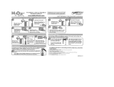
1. After the sediment filter, install the water meter. There is a flow direction arrow on the meter.
Be sure the inlet plumbing is attached to the meter correctly. There should be 18” of hori-
zontal pipe before and after the water meter to ensure it is reading properly.
2. Slide the nut over the connection nipple, apply Teflon tape and install it in the inlet plumbing.
Do not over tighten the plastic nipple or damage could occur.
3. Install the rubber washer gasket in the connecting nut and install the water meter with the
flow arrow pointing away from the inlet fitting. Tighten the nut hand tight channel locks can
be used to tighten the nut an additional 1/4 to 1/2 turn. The rubber washer gasket will seal
the connection so the nut should not be over-tightened.
FLOW
DIRECTION
ARROW
Water Meter Installation Instructions
Installation, Operation and Maintenance Manual
FSF-200-OG, FSF-250-OG, FSF-300-OG,
FSF-500-OG

10
4. Slide the nut over the outlet nipple and install the outlet nipple in the outlet plumbing. Use
Teflon tape to seal the connection and tighten with channel locks. Do no over-tighten the
nipple in the outlet plumbing connection or damage could occur.
5. Install the rubber washer gasket in the nut and tighten the outlet plumbing to the water me-
ter outlet connection. Tighten it hand tight then turn it an additional 1/4 to 1/2 turn with
channel locks. Do not over-tighten or damage could occur.
Water Meter Installation Instructions
Installation, Operation and Maintenance Manual
FSF-200-OG, FSF-250-OG, FSF-300-OG,
FSF-500-OG

11
Any solder joints being soldered near the valve must be done before connecting any piping
to the valves. Always leave at least 6" (152 mm) between the control valve and joints being
soldered when soldering pipes that are connected to the valves. Failure to do this could
cause damage to the valves.
The Fusion Backwashing Filter is equipped with 1” removable connectors. It is recommend-
ed that these connectors are installed in the plumbing fitting using Teflon tape then lubricate
the o-ring on the connector. Remove the red clips and push the connectors into the bypass
valve once they are tight in the plumbing fitting. The red clips can then be re-installed to se-
cure the connectors in the bypass valve.
The inlet and outlet can be identified on the bypass valve. There are arrows stamped in the
bypass valve showing flow direction. The arrow pointing toward the valve is the inlet and the
arrow pointing away from the valve is the outlet
1. Apply Teflon tape to the inlet connector and install the supplied Tee fitting on the inlet
connector of the Superfilter control valve. ATTENTION! If the injection panel is used, the
injection tee is not used because the injection point is on the injection panel. If the injec-
tion panel is used skip to step 5.
All piping should be secured to prevent stress on the bypass valve and connectors.
Installation, Operation and Maintenance Manual
FSF-200-OG, FSF-250-OG, FSF-300-OG,
FSF-500-OG
Superfilter Carbon Tank Installation Instructions

12
2. Install the supplied 1” x 1/2” reducing bushing in the Tee fitting outlet. Be sure to use Tef-
lon tape on the reducing fitting.
3. Apply Teflon tape to the supplied nipple and install it in the outlet of the installed Tee fitting.
Installation, Operation and Maintenance Manual
FSF-200-OG, FSF-250-OG, FSF-300-OG,
FSF-500-OG
Superfilter Carbon Tank Installation Instructions

13
4. Install the injection check valve in the reducing bushing. Be sure to use Teflon tape on the
injection check valve.
5. Lubricate the O-rings on the connectors. Remove the red clips from the bypass on the
valve and install both connectors. Be sure the Tee fitting in on the inlet port.
Installation, Operation and Maintenance Manual
FSF-200-OG, FSF-250-OG, FSF-300-OG,
FSF-500-OG
Superfilter Carbon Tank Installation Instructions

14
6. Attach the inlet and outlet plumbing to the Superfilter control valve. Be sure to check the
stamped arrows on the valve and bypass for inlet/outlet orientation.
All piping should be secured to prevent stress on the bypass valve and connectors.
Installation, Operation and Maintenance Manual
FSF-200-OG, FSF-250-OG, FSF-300-OG,
FSF-500-OG
Superfilter Carbon Tank Installation Instructions

15
Installation, Operation and Maintenance Manual
FSF-200-OG, FSF-250-OG, FSF-300-OG,
FSF-500-OG
Superfilter Carbon Tank Installation Instructions
7. Install the drain line on the 3/4” threaded elbow This should be a 3/4” solid pipe con-
veyed to a floor drain, sink drain or stand pipe. This drain line can be any material al-
lowed by the local code (photos show PEX but PVC is typically the piping used). An air
gap should be established if the local code requires it. Drain line smaller than 3/4” could
cause a restriction on the system and prevent it from backwashing properly. If you re-
duce the drain line to a size smaller than 3/4” BE SURE it can provide the backwash flow
rate requirement of the unit being installed. Drain line larger than 3/4” is acceptable.
The system will drain with pressure, so the drain line can be ran vertically for up to 5’. If
the drain line is ran vertically then along the wall horizontally, make sure the horizontal
pipe has a drop to the final drain point. The system should be plumbed with the least
amount of back pressure on the drain line.
8. The drain elbow can be removed by removing the red clip and pulling the elbow out of
the valve. This will make it easer to connect the plumbing fitting used. BE CAREFUL
not to cross thread the fitting on the elbow. There is a small thread tolerance for this fit-
ting to help reduce a possible leak
NOTE: It may be necessary to install drain line larger than 3/4” on a linear stretch of
drain line that exceeds 15’.

16
1. Install the chemical pump mounting bracket on the solution tank. Center the bracket on the
back side of the tank. Install the two longer screws (supplied) in the outer holes. Tighten all
screws.
Chemical Solution Tank (with Pump) Installation Instructions
Installation, Operation and Maintenance Manual
FSF-200-OG, FSF-250-OG, FSF-300-OG,
FSF-500-OG

17
2. Install the chemical injection pump on the bracket that was installed on the tank us-
ing the screws taped to the bracket.
3. Drill a 1/4” hole in the top of the solution tank and install the tubing into the tank.
Installation, Operation and Maintenance Manual
FSF-200-OG, FSF-250-OG, FSF-300-OG,
FSF-500-OG
Chemical Solution Tank (with Pump) Installation Instructions

18
4. Install the weighted suction screen on the tubing that was inserted in the tank. Push
the tubing down in the tank until the weighted suction screen is around 1” from the
bottom of the tank.
5. Install the other end of the tank suction tube to the chemical injection pump inlet.
The inlet is identified by an arrow point toward the pump. Be sure the sleeve is in-
stalled on the tubing properly. The beveled side of the sleeve should be facing the
pump. Tight the nut hand tight holding the pump fitting. Do not use tools. Hand
tightening will be sufficient.
Installation, Operation and Maintenance Manual
FSF-200-OG, FSF-250-OG, FSF-300-OG,
FSF-500-OG
Chemical Solution Tank (with Pump) Installation Instructions

19
6. Install a piece of tubing on the outlet of the pump. Be sure to orient the sleeve
properly and hand tighten the nut. The outlet is identified by and arrow that is point-
ing away from the pump.
7. Install the other end of the chemical pump outlet tubing to the previously installed in-
jection check valve. Be sure to orient the sleeve properly and hand tighten.
Installation, Operation and Maintenance Manual
FSF-200-OG, FSF-250-OG, FSF-300-OG,
FSF-500-OG
Chemical Solution Tank (with Pump) Installation Instructions

20
1. The wire coming from the previously installed water meter should have three wires.
A black, red and blue wire. The blue wire is not used and should be folded back and
taped to prevent it from making contact with anything.
2. The wire coming from the chemical injection pump will have several colors. Fold
back all wires but the red and black wire. Make sure the wires that are folded back
are not touching each other or anything else. Tape the wires back. Now connect the
black wires together with a wire nut or butt splice connector. Connect the two red
wires using a wire nut or butt splice connector. There is no voltage on these wires.
An enclosure can be used or the wires connections can simply be taped to insulate
the wires if desired.
Installation, Operation and Maintenance Manual
FSF-200-OG, FSF-250-OG, FSF-300-OG,
FSF-500-OG
Chemical Pump Wiring Installation Instructions
/