Page is loading ...

PWFGAC PWFMZ PWFC Series
IOM-WQ-PWFGAC-PWFMZ-PWFCAL
Do not use with water that is microbiologically unsafe or of un-
known quality adequate disinfection before and after the system.
WARNING
!
NOTICE
Hydrocarbons such as Kerosene, Benzene, Gasoline,
etc., may damage products that contain O-rings or plastic
components. Exposure to such hydrocarbons may cause the
products to leak. Do not use the product(s) contained in this
document on water supplies that contain Hydrocarbons such
as Kerosene, Benzene, Gasoline, etc.
WARNING
!
Read this Manual BEFORE using this equipment.
Failure to read and follow all safety and use information can
result in death, serious personal injury, property damage, or
damage to the equipment.
Keep this Manual for future reference.
You are required to consult the local building and plumbing
codes prior to installation. If the information in this manual
is not consistent with local building or plumbing codes,
the local codes should be followed. Inquire with governing
authorities for additional local requirements.
WARNING
!
Need for Periodic Inspection/Maintenance: This product must
be tested periodically in compliance with local codes, but at least
once per year or more as service conditions warrant. All prod-
ucts must be retested once maintenance has been performed.
Corrosive water conditions, and/or unauthorized adjustments or
repair could render the product ineffective for the service intended.
Regular checking and cleaning of the product’s internal compo-
nents helps assure maximum life and proper product function.
WARNING
!
Series PWFGAC, PWFMZ, PWFCAL
Installation, Operation
and Maintenance Manual
System Specification Table ................................2
Safety Information .......................................3
General Warnings ..................................... 3-4
How to Use this Manual ...................................... 4
Control Valve Function and Cycles of Operation .................... 4
Installation Preview .......................................... 4
Pre-Installation Considerations ...................................5
General Installation Instructions ...................................6
Bypass Valve Installation ...................................... 7
Move Filter System Into Place .................................. 8
Connect the Drain Line ...................................8
Start Up...............................................9
PWF System Programming ...............................10
PWF Quick Programming Guide ...........................11
PWF OEM System Setup Programming................... 12-13
PWF Installer Display and Settings....................... 14-15
PWF User Displays .................................. 15-16
NOTES ..............................................17
Table of Contents

2 PWF Filter Systems
Specifications
Feed Water Parameters
Minimum inlet pressure: 30 psig
Maximum operating pressure: 125 psig
Minimum water temperature: 40°F (5°C)
Maximum water temperature: 110°F (43°C)
Power
Voltage: 120VAC
Frequency: 60Hz
Power consumption: 7 Watts Maximum
Installation
Location: Indoors (Protect from direct sunlight)
Minimum ambient temperature: 40°F (5°C)
Maximum ambient temperature: 110°F (50°C)
Drain Flow Rates
The drain system these filters are plumbed to must be able to accept
the listed drain volumes for a period of 27 minutes.
Micro Z™ Filters
9" X 48", 1 cubic ft. 5.3 gpm
10" X 54", 1.5 cubic ft. 7.5 gpm
12" X 52", 2 cubic ft. 11 gpm
13" X 65", 3 cubic ft. 15 gpm
Carbon Filters:
9" X 48", 1 cubic ft. 4.2 gpm
10" X 54", 1.5 cubic ft. 5.3 gpm
12" X 52", 2 cubic ft. 7.5 gpm
13" X 65", 3 cubic ft. 10 gpm
16" X 65", 4 cubic ft. 11 gpm
Calcite Filters:
10" X 54", 1.5 cubic ft. 7.5 gpm
12" X 52", 2 cubic ft. 11 gpm
13" X 65", 3 cubic ft. 15 gpm
MODEL NO. VALVE MINERAL TANK
SIZE
MEDIA CUBIC
FOOT
GRAVEL (LBS) PEAK SERVICE FLOW
(GPM)
PRESSURE DROP
(PSI)
BACK WASH
(GPM)
FLOOR SPACE
LXWXH
PWFGAC1 Time Clock 9" X 48" 1 10 4 <15 4.2 16" X 10" X 55"
PWFGAC15 Time Clock 10" X 54" 1.5 10 6 <15 5.3 16" X 11" X 62"
PWFGAC2 Time Clock 12" X 52" 2 30 8 <15 7.5 17" X 13" X 60"
PWFGAC3 Time Clock 14" X 65" 3 40 11 <15 10 18" X 14" X 74"
PWFGAC4 Time Clock 16" X 65" 4 60 14 <15 11 20" X 17" X 74"
MODEL NO. VALVE MINERAL TANK
SIZE
MEDIA CUBIC
FOOT
GRAVEL
(LBS)
PEAK SERVICE FLOW
(GPM)
PRESSURE DROP
(PSI)
BACK WASH
(GPM)
FLOOR SPACE
LXWXH
PWFMZ1 Time Clock 9" X 48" 1 10 5 - 9 15 5.3 16" X 10" X 55"
PWFMZ15 Time Clock 10" X 54" 1.5 10 7 - 10 15 7.5 16" X 11" X 62"
PWFMZ2 Time Clock 12" X 52" 2 30 9 - 15 15 11 17" X 13" X 60"
PWFMZ3 Time Clock 14" X 65" 3 40 13 - 21 15 15 18" X 14" X 74"
MODEL NO. VALVE MINERAL TANK
SIZE
MEDIA CUBIC
FOOT
GRAVEL
(LBS)
PEAK SERVICE FLOW
(GPM)*
PRESSURE DROP BACK WASH
(GPM)
FLOOR SPACE
L X W X H
PWFCAL15 Time Clock 10" X 54" 1.5 10 7 - 10 <15 7.5 16" X 11" X 62"
PWFCAL2 Time Clock 12" X 52" 2 30 9 - 15 <15 11 17" X 13" X 60"
PWFCAL3 Time Clock 13" X 65" 3 40 13 - 21 <15 15 18" X 14" X 74"
*Note: Peak service flow rate is for intermittent use only and is not to be interpreted as continuous service flow rate capability. These systems are designed to treat the domestic water used in a
single family dwelling. For irrigation water treatment or higher volume applications please contact your Watts representative. Peak service flow rates are based on a 15 psi drop.
Optimum service flow rate is specific to water chemistry and will vary.
PWFMZ Series
PWFGAC Series
PWFCAL Series

PWF Filter Systems 3
WARNING
!
This water conditioner’s control valve conforms to UL/
CE Standards. Generic valves were tested and certified for
compliance as verified by the agency listing. This water
conditioning system is to be used only for potable water.
Inspect the water conditioning system for carrier shortage or
shipping damage before beginning installation.
Operating Perameters:
• Operating ambient temperature: 40° to 110°F (5° to 43°C).
• Operating water temperature: 40° to 110°F (5° to 43°C).
• Operating water pressure range : 25 to 120 psi (1.7 to
8.27bar).
Installation Perameters: All plumbing should be done in
accordance with local plumbing codes.
• Do not use pipe dope or other sealants on threads. Use Teflon
tape on the threaded inlet, outlet and drain fittings. Teflon tape
is not necessary on the nut connection or caps because of
o-ring seals.
• All plastic connections should be hand tightened. Teflon® tape
may be used on connections that do not use an O-ring seal.
Do not use pipe dope type sealants on the valve body. Do not
use pliers or pipe wrenches.
• Observe drain line requirements.
• Keep the media tank in the upright position. Do not turn upside
down or drop. Turning the tank upside down or laying the tank
on its side can cause media to enter the valve.
• The pipe size for the drain line should be a minimum of ½”.
Backwash flow rates in excess of 7 gpm (26.5 lpm) or length in
excess of 20’ (6.1m) require ¾” drain line.
• Do not support the weight of the system on the control valve
fittings, plumbing, or the bypass.
Environmental:
• Use only regenerants designed for water conditioning. Do not
use ice melting salt, block salt or rock salt.
During cold weather it is recommended that the installer warm
the valve to room temperature before operating.
Teflon
®
is a trademark of E.I. duPont de Nemours.
• Do not use petroleum-based lubricants such as Vaseline, oils
or hydrocarbon-based lubricants. Use only 100% silicone
lubricants.
• Do not allow this water conditioning system to freeze. Damage
from freezing will void this water conditioning system’s
warranty.
• HYDROCARBONS SUCH AS KEROSENE, BENZENE,
GASOLINE, ETC., MAY DAMAGE PRODUCTS THAT
CONTAIN O-RINGS OR PLASTIC COMPONENTS.
EXPOSURE TO SUCH HYDROCARBONS MAY
CAUSE THE PRODUCTS TO LEAK. DO NOT USE THE
PRODUCT(S) CONTAINED IN THIS DOCUMENT ON
WATER SUPPLIES THAT CONTAIN HYDROCARBONS
SUCH AS KEROSENE, BENZENE, GASOLINE, ETC.
• THIS WATER METER SHOULD NOT BE USED AS THE
PRIMARY MONITORING DEVICE FOR CRITICAL OR
HEALTH EFFECT APPLICATIONS.
• Do not use Vaseline, oils, other hydrocarbon lubricants or spray
silicone anywhere. A silicone lubricant may be used on black
o-rings but is not necessary.
General Installation Guidelines
Electrical:
• Use only the power transformer supplied with this water
conditioning system.
• All electrical connections must be completed according to local
codes.
• The power outlet must be grounded.
• All electrical connections must be connected according to local
codes. (Be certain the outlet is uninterrupted.)
• Install grounding strap on metal pipes.
• The power adapter comes with a 15 foot power cord and is
designed for use with the control valve. The power adapter is for
dry location use only. The control valve remembers all settings
until the battery power is depleted if the power goes out.
• After the battery power is depleted, the only item that needs to
be reset is the time of day; other values are permanently stored
in the nonvolatile memory. The control valve battery is not
rechargeable but is replaceable.
• No user serviceable parts are on the PC board, the motor or
the power adapter. The means of disconnection from the main
power supply is by unplugging the power adapter from the
wall.
• Install an appropriate grounding strap across the inlet and
outlet piping of the water conditioning system to ensure that a
proper ground is maintained.
• To disconnect power, unplug the AC adapter from its power
source.
Soldering:
• Use only lead-free solder and flux, as required by federal and
state codes, when installing soldered copper plumbing.
• Use caution when installing soldered metal piping near the
water conditioning system. Heat can adversely affect the
plastic control valve and bypass valve.
• Solder joints near the drain must be done prior to connecting
the drain line flow control fitting. Leave at least 6” between the
drain line control fitting and solder joints when soldering pipes
that are connected on the drain line control fitting. Failure to do
this could cause interior damage to the drain line flow control
fitting.
• When assembling the installation fitting package (inlet and
outlet), connect the fitting to the plumbing system first and
then attach the nut, split ring and o-ring. Heat from soldering
or solvent cements may damage the nut, split ring or o-ring.
Solder joints should be cool and solvent cements should be
set before installing the nut, split ring and o-ring. Avoid getting
primer and solvent cement on any part of the o-rings, split
rings, bypass valve or control valve.
Control Valve:
• This glass filled Noryl
1
(or equivalent) fully automatic control
valve is designed as the primary control center to direct and
regulate all cycles of a water softener or filter.
• The control valve, fittings and/or bypass are designed to
accommodate minor plumbing misalignments but are not
designed to support the weight of a system or the plumbing.
• The nuts and caps are designed to be unscrewed or tightened
by hand or with the special plastic wrench. If necessary a
pliers can be used to unscrew the nut or cap. Do not use a
pipe wrench to tighten or loosen nuts or caps. Do not place a
screwdriver in the slots on caps and/or tap with a hammer.
• After completing any valve maintenance involving the drive
assembly or the drive cap assembly and pistons unplug power
source jack from the printed circuit board (black wire) and plug
back in or press and hold NEXT and REGEN buttons for 3

4 PWF Filter Systems
1
Noryl is a trademark of Sabic.
How To Use This Manual
This installation manual is designed to guide the installer through
the process of installing and starting up water conditioning systems
featuring the PWF controller.
This manual is a reference and will not include every system
installation situation. The person installing this equipment should
have:
• Training on the control valve.
• Knowledge of water conditioning and how to determine proper
control settings.
• Adequate plumbing skills.
Control Valve Function and
Cycles of Operation
The time clock control valve has two calendar options for
regeneration frequency: 1. an option where the user can choose the
number of days (1-99) between each backwash; and 2. a seven-
day option where the user can choose which day(s) of the week a
backwash should occur.
The control valve uses no traditional fasteners (e.g. screws); instead
clips, threaded caps and nuts and snap type latches are used.
Caps and nuts only need to be firmly hand tightened because radial
seals are used. Tools required to service the valve include one small
blade screw driver, one large blade screw driver, pliers and a pair of
hands. A plastic wrench is available which eliminates the need for
screwdrivers and pliers. Disassembly for servicing takes much less
time than comparable products currently on the market. Control
valve installation is made easy because the distributor tube can be
cut ½" above to ½" below the top of tank thread. The distributor
tube is held in place by an o-ring seal and the control valve also has
a bayonet lock feature for upper distributor baskets.
The AC adapter power pack comes with a 15 foot power cord and is
designed for use with the control valve. The AC adapter power pack
is for dry location use only. If the power goes out, only the time of
day needs to be reset. All other values are permanently stored in the
nonvolatile memory.
Installation Preview
Conduct a visual check of all equipment for any damage that may
have occurred during shipment.
If there is obvious damage to any equipment, it should be noted
on the carrier’s Bill Of Lading. Open and inspect the contents of all
closed crates, cartons, etc. and inspect for concealed damage. The
manufacturer is not liable for any dam-age during transit.
Position the equipment in its proper location, setting on a flat
surface. Level equipment as required. Equipment out of plumb can
exhibit poor flow characteristics, which will affect the performance of
the system.
Units are shipped with media (resin & gravel), distributions tube, and
control valve installed. Double-check the valve installation on the
tank. Tighten if necessary.
Unit should be positioned with the valve control facing forward.
Check the main line water pressure. The softener is designed for a
minimum of 20 psi and a maximum of 125 psi working pressure. If
the line pressure exceeds this limit, a pressure-reducing valve should
be installed.
Maximum allowable water temperature is 40°F (4°C) – 110°F (38°C).
A 120vac 60 cycle electrical source must be available for operation
of the controller.
Connect raw water supply line to the inlet valve connection. Connect
treated water outlet to service line. It is suggested that the pipe size
be equal or one size larger than the valve connection.
NOTICE
NOTICE
General Warnings (continued)
Installation Guidelines:
seconds. This resets the electronics and establishes the
service piston position. The display should flash all word-
ing, then flash the software version and then reset the
valve to the service position.
• The control valve is compatible with a variety of
regenerants and resin cleaners. The control valve is
capable of routing the flow of water in the necessary paths
to regenerate or backwash water treatment systems. The
injector regulates the flow of brine or other regenerants.
The control valve regulates the flow rates for backwashing,
rinsing, and the replenishing of treated water into a
regenerant tank, when applicable.
• Control valve installation is made easy because the
distributor tube can be cut ½” above to ½” below the top
of tank thread. The distributor tube is held in place by an
o-ring seal and the control valve also has a bayonet lock
feature for upper distributor baskets.
WARNING
!

PWF Filter Systems 5
Safety Information
This water conditioner’s control valve conforms to UL/CE Standards.
Generic valves were tested and certified for compliance as verified by
the agency listing.
• Please review the entire Installation and Operation Manual
before installing the water conditioning system.
• As with all plumbing projects, it is recommended that a
trained professional water treatment dealer install the water
conditioning system. Please follow all local plumbing codes for
installing this water conditioning system.
• This system will not make microbiologically unsafe water safe.
Water that is unsafe must be treated separately from this
conditioner.
• This water conditioning system is to be used only for potable
water.
• Inspect the water conditioning system for carrier shortage or
shipping damage before beginning installation.
• Use only lead-free solder and flux, as required by federal and
state codes, when installing soldered copper plumbing.
• Use caution when installing soldered metal piping near the
water conditioning system. Heat can adversely affect the plastic
control valve and bypass valve.
• All plastic connections should be hand tightened. Teflon® tape
may be used on connections that do not use an O-ring seal.
Do not use pipe dope type sealants on the valve body. Do not
use pliers or pipe wrenches.
• Use only the power transformer supplied with this water
conditioning system.
• All electrical connections must be completed according to local
codes.
• The power outlet must be grounded.
• Install an appropriate grounding strap across the inlet and
outlet piping of the water conditioning system to ensure that a
proper ground is maintained.
• To disconnect power, unplug the AC adapter from its power
source.
• Observe drain line requirements.
• Operating water temperature: 40° to 110°F (4° to 43°C).
• Keep the media tank in the upright position. Do not turn upside
down or drop. Turning the tank upside down or laying the tank
on its side can cause media to enter the valve.
• Use only regenerants designed for water conditioning. Do not
use ice melting salt, block salt or rock salt.
During cold weather it is recommended that the installer warm
the valve to room temperature before operating.
Teflon
®
is a trademark of E.I. duPont de Nemours.
• Do not use petroleum-based lubricants such as Vaseline, oils
or hydrocarbon-based lubricants. Use only 100% silicone
lubricants.
• Do not support the weight of the system on the control valve
fittings, plumbing, or the bypass.
• Do not allow this water conditioning system to freeze. Damage
from freezing will void this water conditioning system’s warranty.
• Observe all warnings and notes that appear in this
manual
Pre-Installation Considerations
(continued)
G. Pre Installation and Loading of Media
Systems that are 13” in diameter and larger are not loaded with
media. These systems must be loaded with media before placing
into service. To load a system follow the below steps.
1. Cap the top open end of the distributor tube with tape and
plastic sheeting to keep foreign debris from entering the
distributor tube. This cap must be secure and not come off
during media loading.
2. Place the distributor tube, screen end down, into the mineral
tank and center it in the bottom. The top of the distributor tube
should be flush with the top of the tank.
3. Make sure the plastic and tape cap is secure to the top of the
distributor tube, place a funnel on the top of the tank and load
first the gravel (if different sizes of gravel are used load the largest
gravel first, then the smaller gravel) then the resin media into the
tank. The cap must not come off of the distributor tube during
the loading of the media.
4. Remove the plastic cap from the distributor tube. DO NOT PULL
UP ON THE DISTRIBUTOR TUBE when removing the cap. The
distributor tube top must remain flush with the top of the tank.
5. Clean any media from the threads and top of the mineral tank.
6. Lubricate the O-rings on the bottom of the control valve
(distributor pilot O-ring and top of tank O-ring). Use non-
petroleum based silicone lubricant only.
7. Place the control valve on top of the tank. When doing this step,
seat the top of the distributor tube inside the centered O-ring
sealed port on the bottom of the valve first then press the valve
down until the tank threads come in contact with the valve
threads. This ensures that the distributor tube is properly seated
into the bottom of the control valve. Thread the valve on to the
tank clockwise. Be careful not to cross thread the valve or over
tighten it. A hand tight snug fit is appropriate for the control valve
torque. A wrench is not necessary. Do not use thread sealant or
PTFE tape on the valve base threads.
8. The system is now ready for installation. Follow the Installation
Section in the Installation, Operation and Maintenance Manual.

6 PWF Filter Systems
WARNING
!
Do not exceed water pressure of 120 psi (8.2 bar). Do not
exceed 110°F (43.3°C). Do not subject unit to freezing
conditions.
General Installation Instructions
1. Turn off water heater(s).
2. Turn off the main water supply to the home and open an inside
faucet (cold and hot) to relieve any pressure within the plumbing
system.
Select Location
1. Place the system in the desired installation location. Make sure
that the location is level and sturdy enough to support the weight
of the system once it is in operation.
2. You will need to locate the filter system at least 10 feet away
from the hot water heater so that hot water does not backup
and damage the filter system.
3. You will need a drain close by for disposal of regenerated waste-
water.
4. If installing the filter system in an outside locations, make sure to
protect softener from the elements, such as freezing tempera-
tures, rain, sunlight and contamination
System Components Described
15
SYSTEM COMPONENTS DESCRIBED
SERVICE INSTRUCTIONS
DRIVE ASSEMBLY
Remove the valve cover to access the drive assembly.
Disconnect the power source plug (black wire) from the PC
board prior to disconnecting the motor or water meter plugs
from the PC board. The motor plug connects to the two-pin
jack on the left-hand side of the PC board. The power source
plug connects to the four-pin jack. The four-pin jack is
between the two-pin and three-pin jacks. The water meter
plug (gray wire) connects to the three.
The PC board can be removed separately from the drive brack-
et but it is not recommended. Do not attempt to remove the dis-
play panel from the PC board. Handle the board by the edges.
To remove the PC board from the drive bracket, unplug the
power, water meter and motor plugs from the PC board. Lift the
middle latch along the top of the drive bracket while pulling out-
ward on the top of the PC board. The drive bracket has two
plastic pins that fit into the holes on the lower edge of the PC
board. Once the PC board is tilted about 45˚ from the drive
bracket it can be lifted off of these pins. To reinstall the PC
board, position the lower edge of the PC board so that the
holes in the PC board line up with the plastic pins. Push the top
of the PC board towards the valve until it snaps under the
middle latch, weave the power and water meter wires into the
holders and reconnect the motor water meter and power plugs.
The drive bracket must be removed to access the drive cap
assembly and pistons or the drive gear cover. It is not
necessary to remove the PC board from the drive bracket to
remove the drive bracket. To remove the drive bracket start by
removing the plugs for the power source and the water meter.
Unweave the wires from the side holders. Two tabs on the
top of the drive back plate hold the drive bracket in place.
Simultaneously lift the two tabs and gently ease the top of
the drive bracket towards your body. The lower edge of
the drive bracket has two notches that rest on the drive
back plate. Lift up and outward on the drive bracket to
disengage the notches.
To reassemble seat the bottom of the drive bracket so the
notches are engaged at the bottom of the drive back plate.
Push the top of the drive bracket towards the two latches. The
drive bracket may have to be lifted slightly to let the threaded
piston rod pass through the hole in the drive bracket. Maintain
a slight engaging force on top of the drive bracket while
deflecting the bracket slightly to the left by pressing on the
side of the upper right corner. This helps the drive gears
mesh with the drive cap assembly. The drive bracket is
properly seated when it snaps under the latches on the drive
back plate. If resistance is felt before latching, then notches
are not fully engaged, the piston rod is not in hole, the wires
are jammed between the drive bracket and drive back plate,
or the gear is not engaging the drive cap assembly.
To inspect drive gears, the drive gear cover needs to be
removed. The drive gear cover is held in place on the drive
bracket by three clips. The largest of the three clips is always
orientated to the bottom of the drive bracket. Before trying to
remove the drive gear cover, the drive bracket must be
removed from the drive back plate. The drive gear cover can
be removed from the drive bracket without removing the
motor or the PC board. Simultaneously, push in and down on
the large clip at the bottom and the clip on the left-hand side
of the drive bracket behind the PC board. Keep your other
fingers behind the drive gear cover so the drive gears do not
drop on the ground. Replace broken or damaged drive gears.
Do not lubricate any of the gears. Avoid getting any foreign
matter on the reflective coating because dirt or oils may inter-
fere with pulse counting.
The drive gear cover only fits on one way, with the large clip
orientated towards the bottom. If all three clips are outside of
the gear shroud on the drive bracket the drive gear cover slips
easily into place.
The drive bracket does not need to be removed from the drive
plate if the motor needs to be removed. To remove the motor,
disconnect the power and motor plugs from the jacks on the PC
Service Instructions
Figure 17: Figure 18: Figure 19 Figure 20::
NOTICE
NOTICE
NOTICE
Install a By-Pass
Always install a bypass, either a 3-way valve system or the standard
bypass for the valve you have. This will allow you to shut off the
water supply to the softener, but still have water in the house if the
softener is in need of repair.
After a location has been determine install bypass onto the control
valve. (On page 7, Figures 1 and 3 show standard bypass on valve.)
(Figures 2 and 4 show 3-way by pass plumbing.)
If installing a 3-way bypass valve, do so now.
Close main water supply valve, at the well or at the water meter.
Shut off electrical or fuel supply to the water heater.
Open all faucets to drain pipes.
The bypass (provided) easily connects to the valve body using nuts
that only require hand tightening. The split ring retainer design holds
the nut on and allows load to be spread over the entire nut surface
area reducing the chance for leakage.
Make certain the nut is placed on first, then the split retainer ring, fol-
lowed by the o-ring to make the seal. A silicon lubricant may be used
on the black o-ring seals. This design allows for an approximate
2-degree misalignment of the plumbing. This design will allow for
minor plumbing misalignments, but should never handle the weight
of the plumbing system.
Once by-pass installed, place the by-pass valve in the by-pass posi-
tion

PWF Filter Systems 7
Bypass Valve Installation
7
INSTALLATION
Figure 1: Plumbing with by pass (Standard).
Figure 3: Bypass (standard).
Figure 6:
Figure 2: Plumbing with 3-way b pass.
Figure 4: 3-way bypass plumbing.
When installing sweat copper follow state and fed-
eral codes by using a lead free solder and flux. Use
a joint compound to seal threaded pipe. Some
homes use the cold water pipes for an electrical
ground (metal only). When finished with plumbing,
a ground wire should be connected to the copper
pipes to complete the ground circuit. Use two
clamps and #4 copper for this.
Figure 5:
When installing sweat copper follow state and
federal codes by using a lead free solder and flux.
Use a joint compound to seal threaded pipe. Some
homes use the cold water pipes for an electrical
ground (metal only). When finished with plumbing,
a ground wire should be connected to the copper
pipes to complete the ground circuit. Use two
clamps and #4 copper for this.
Figure 5:
Figure 6:

8 PWF Filter Systems
NOTICE
When assembling the installation fitting package, connect
the fitting to the plumbing system first and then attach the
nut, split ring and o-ring. Heat from soldering or solvent
cements may damage the nut, split ring, and o-ring. Make
sure solder joints are cool before assemble is started.
Split ring retainer design holds the nut on and allows load to be
spread over the entire nut surface area reducing the chance for leak-
age. The split ring design, incorporated into the installation fittings
allows approximately 2 degrees off axis alignment to the plumbing
system. The installation fittings are designed to accommodate minor
plumbing misalignments but are not designed to support the weight
of a system or the plumbing.
When assembling the installation-fitting package, connect the fitting
to the plumbing system first and then attach the nut, split ring and
o-ring. Heat from soldering or solvent cements may damage the nut,
split ring, or o-ring. Solder joints should be cool and solvent cements
should be set before installing the nut, split ring, and o-ring. Avoid
getting primer and solvent cement on any part of the o-rings, split
rings, and bypass valve or control valve. Solvent cements and prim-
ers should be used in accordance with the manufacturer’s instruc-
tions.
Move Filter System Into Place
1. Connect the cold water supply to the inlet of the water condition-
ing system. While constructing the supply line, install a master
supply valve (user supplied) in the supply line and close it.
2. Connect the feed water line to the home to the outlet of the
system.
3. Make sure floor is level.
Measure, cut, and install pipe and fit-
tings to the bypass valve (dry fit only to
make sure you have a proper fit) inlet
and outlet side. Be sure hard water is
supplied to the inlet side. Trace pipe
to be sure.
The installation fittings connect to the
control valve or the bypass valve using
nuts that only require hand tighten-
ing. Hand tighten nut connections
between control valve and installation
fittings,control valve and bypass valve,
and bypass valve and installation fit-
tings allow for easy serviceability. Do
not use a pipe wrench to tighten nuts
on installation fittings. Hand tighten
only.
Slip the nut onto the fitting first, then the split ring second and the
o-ring last. Hand tighten the nut. If the fitting is leaking tightening the
nut will not stop the leak. Remove the nut, remove the fitting, and
check for damage or misalignment of the o-ring.
Do not use pipe dope or other sealant on threads. Teflon tape must
be used on the threads of the 1" NPT elbow and the 1/4" NPT con-
nection and on the threads for the drain line connection. Teflon tape
is not necessary on the nut connection or caps because of o-ring
seals.
Connect the Drain Line
1. Plumb the drain line to an appropriate drain abiding by all local,
city, and state codes. Use a 3/4” drain line for backwash flow
rates of 7 gpm or for drain lines of 7 gpm and less that exceed
20’ in length. Use a 1” drain line for backwash flow rates of 10
gpm and 12 gpm.
2. If the drain line is a 5/8" flexible poly tube, slide the nut onto the
poly tube, then place the poly tube insert into the end of the poly
tube and tighten the nut on to the 3/4" drain line fitting. The nut
is only designed for use with flexible poly tube. Use other nuts if
attaching different materials. Run line to a drain. Making sure you
have a 1 1/2" airgap. You may use a floor drain, standpipe or any
open type drain (see Fig 7).
Do not use Vaseline, oils, or other unacceptable lubricants on
o-rings. A silicon lubricant may be used on the black o-ring.
Use a pliers or crescent wrench to tighten or unscrew the nut. Do
not use a pipe wrench to tighten or loosen nut. Do not use pipe
dope or other sealant on threads. Use Teflon tape on the threads of
the drain line control fitting when installing 3/4" NPT or 1" straight
fitting.
Figure 7: Also be sure drain line has an air gap.

PWF Filter Systems 9
Figure 8: Drain Line Connection
9
INSTALLATION
STEP 5: Connect the Drain Line
If the drain line is a 5/8" flexible poly tube, slide the nut onto
the poly tube, then place the poly tube insert into the end of
the poly tube and tighten the nut on to the 3/4" drain line fit-
ting. The nut is only designed for use with flexible poly tube.
Use other nuts if attaching different materials. Run line to a
drain. Making sure you have a 1 1/2" airgap. You may use a
floor drain, standpipe or any open type drain (see Fig 10).
Do not use Vaseline, oils, or other unacceptable lubricants on
o-rings. A silicon lubricant may be used on the black o-ring.
Use a pliers or crescent wrench to tighten or unscrew the nut.
Do not use a pipe wrench to tighten or loosen nut. Do not use
pipe dope or other sealant on threads. Use Teflon tape on the
threads of the drain line control fitting when installing 3/4"
NPT or 1" straight fitting.
Figure 10: Also be sure drain line has an air gap.Figure 11: Drain Line Connection
Figure 12: Operating Mode Figure 13: Bypass Mode Figure 14: Bypass Mode
Figure 9: Brine Draw Connection.
STEP 5: Start-up
Place the bypass valve in the “bypass” position or mode
(see figures 12-14 below.)
Open the main water supply valve.
Open a couple of cold water faucets that are to be conditioned
and let run until air is expelled and pipes are full.
Open the outlet valve of the bypass.
Close the bypass valve.
Press and hold the regen button on the keypad for 3 seconds.
This will put the valve in manual mode. Now press the Regen
button twice. This will put the system in backwash. Slowly open the
inlet valve. (Open the valve a little at a time, pausing several times
to allow the unit to fill slowly and expel air.) When the tank has filled
and a steady flow to the drain is achieved, let the system run until
clear water can be seen coming from the drain line. When water is
clear press the regen button 4 times. This will take the valve back
to service position. Open several cold water and hot water faucets
and let run until hot water heater is full and cold water faucets have
expelled trapped air. Turn electrical power back on or re-light the
hot water heater. Now continue with control valve setup.
Figure 9: Operating Mode Figure 10: Bypass Mode Figure 11: Bypass Mode
Start Up
1. Confirm that the bypass valve is in the bypass position (see im-
ages 9, 10 & 11 below)
2. Place the bypass valve in the “bypass” position or mode (see
figures 12-14 below.)
3. Open the user supplied feed water valve. Check for leaks and
repair as needed.
4. Open the outlet valve of the bypass.
5. Open a couple inside hot and cold faucets until all air has been
purged from the plumbing system. then close the faucets.
6. Initiate an Immediate Manual Regeneration by pressing and hold-
ing the “REGEN” button for 3 seconds. This will place the system
into “Backwash” mode, unplug the system from its electrical
outlet once it has cycled into the backwash position. This will stall
the unit in the “Backwash” mode so all air can be purged from
the tank.
7. Close the bypass valve.
8. Adjust the user supplied feed water valve to 1/4 open and place
the bypass valve into the “Service/Operating Mode” position.
9. Air will come out of the drain line until the backwashing tank is
completely purged of air. Then water will flow to drain. Allow
water to flow to drain for 15 minutes or until the water to drain is
clear of resin color throw.
10. Plug the system back into the electrical outlet and manually cycle
the control valve through the remaining regeneration steps by
pressing the “Next” button until it arrives in the Service position.
11. Check for system for leaks and repair as needed.
12. Installation is now complete and the system is ready for program-
ming.

10 PWF Filter Systems
PWF System Programming
PWF Quick Programming Guide
A quick programming guide has been listed below for convenience specifically for the PWF series filter systems. For other programming
requirements not listed in the Quick Programming Guide, please see the detailed programming section of this manual.
NOTICE
The electronics in the PWF control valve are used across a wide
variety of control valves and applications, including backwashing
filters. All programming for the electronics has been included in this
manual for reference however the valve must be programmed for
Twin Alternating Softening Applications when called for during valve
programming.

PWF Filter Systems 11
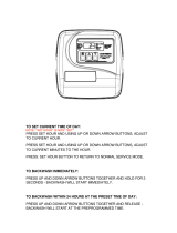
Press the Set button approximately
5 seconds
Adjust hours using the Up and Down arrow buttons
Press the Set button to advance to
the minutes.
Adjust minutes with the Up and Down arrow buttons.
Press the Set button to set time To Exit
Chart 1: Setting Time of Day
NOTICE
Once in the programming settings, simply use the UP and DOWN arrow buttons to change values
NOTICE
To enter the Master Programming
mode, press and hold the SET and
UP arrow buttons simultaneously
for 3 – 5 seconds The Hour display will start flashing again.
Press and Hold the SET and UP
arrow buttons simultaneousy for 3 -
5 seconds, again.
Screen will change from the time to "P" with a number flashing. This indicates you are now
in the Master Programming Mode. Using the Up and Down arrow buttons, set this to "P9"
for Filter Systems
Press the SET Button Next you will set Days to REGEN, set this to 99 Days
Press the SET Button
Next you will set "dP" (Differential Pressure Switch). For Watts units, there should be an
arrow pointing to REGEN TIME. If not, press the Up arrow one time.
Press the SET Button This will complete Master Programming Steps
Chart 2: Master Programming
To enter Installation Display Setting
Programming mode, press and hold
the SET and UP arrow buttons
simultaneously for 3 - 5 seconds
Set the Regeneration Time clock to the hour the regeneration should occur by using the Up
and Down arrow buttons (an arrow points to PM after 12:00 noon). Late night/midnight is
best, this is the time when no water is liekly to be used.
Press SET Button Adjust minutes with the Up and Down arrow buttons.
Press SET Button
Next you set the Days to Regen. Se the number of days between regenerations, normally 3
days for Filter Systems (the allowable rand is from 1 to 99 days). Watts recommends filter
systems to regenerate every 3 days
Press SET Button This will complete the Installer Programming
Chart 3: Installer Programming
Next you will need to set up Installer Programming, this MUST be done in addition to the Master Programming
NOTICE
Programming completed, Valve will return to normal mode and will be in service.
General Operation
When the system is operating one of two displays will be show: time of day (hour only) or days until the next backwash.
Pressing the Up or Down buttons will toggle between the two displays.
If you have additional questions regarding your water softener programming, please contact
Pure Water Technical Support at 1.800.224.1299, then press #2
Advance Programming Features
The following section explains the advanced programming features of the valve. It is intended for use by the Service Tech-
nician or Water Treatment Dealer. DO NOT attempt to access these features if you are not qualified. Improper settings can
cause the unit to malfunction and could have a negative effect on the water quality.
PWF Quick Programming Guide

12 PWF Filter Systems
Programming
STEP 1SS – From normal mode, press SET HOUR + UP buttons simultaneously for 3 seconds and
release. Then press SET HOUR + UP buttons simultaneously for 3 seconds and release.
STEP 2SS – Choose the desired program by pressing the UP or DOWN buttons. Prior to selecting a
program, verify the correct valve body, main piston, regenerant piston, and stack are being used, and that
the injector or injector plug(s) are in the correct locations. See Compliance Table in Service Instructions
under Injector Cap, Screen, Injector Plug and Injector section and Figure 6. Press SET HOUR button to
go to Step 3SS.
Program
Cycle Sequence, Adjustable Default Times (minutes)
C1
1st Backwash
C2
Regenerate
C3
2nd Backwash
C4
Rinse
C5
Fill
P0 3 50 3 3 1-99
P1 8 50 8 4 1-99
P2 8 70 10 6 1-99
P3 12 70 12 8 1-99
P4 10 50 Skipped 8 1-99
P5 4 50 Skipped 4 1-99
P6 12 6 Skipped 12 1-99
P7 6 Skipped Skipped 4
P8 10 Skipped Skipped 6
The control valve offers multiple procedures that allow the valve to be modifi ed to suit the needs of the
installation. These procedures are:
• OEM System Setup
• Installer Displays & Settings (either 1-99 Days Between Regeneration option or 7-Day option)
• User Displays
These procedures can be accessed in any order. Details on each of the procedures are provided below and
on the following pages.
When in operation, normal user displays show the time of day or days remaining before backwash. When
stepping through a procedure, if no buttons are pressed within five minutes the display returns to a normal
user display. Any changes made prior to the five minute time out are incorporated.
To quickly exit Installer Displays & Settings or OEM Setup, simultaneously press SET HOUR + DOWN. Any
changes made prior to the exit are incorporated.
To reinitialize the control valve, check to make sure the valve is in the User Display. Then simultaneously
press SET HOUR + DOWN or unplug power source plug (black wire) on the circuit board, and plug back in.
OEM System Setup
Regeneration Cycles and Times for Different Programs
STEP 3SS – If program P0 through P6 was selected, enter in the minutes of fill using the UP or DOWN
buttons. The allowable values vary from a low of 1 to a high of 99. If program P7, P8 or P9 was selected,
dashes will appear for minutes of fill. Press SET HOUR button to go to Step 4SS. Note: For each minute
of fill 0.5 gallons of water
STEP 1SS
STEP 2SS
SET
HOUR
SET
HOUR
SET
HOUR
Regen
Min. Fill
Regen
Hour
Time-Hour
PM
Days To Regen
STEP 3SS
Regen
Min. Fill
Regen
Hour
Time-Hour
PM
Days To Regen
SET
HOUR

PWF Filter Systems 13
is added to the solution tank. With salt (sodium chloride) this
equates to approximately 1 1/2 pounds of salt per minute of fill.
STEP 4SS — Use UP or DOWN buttons to switch between:
• 1-99 Days Between Regen; or
• 7-Day.
Press SET HOUR button to go to Step 5SS.
STEP 5SS — Use UP or DOWN buttons to switch between 60 Hz
or 50 Hz option. Press SET HOUR button to go to Step 6SS.
STEP 6SS — If a differential pressure switch is installed and actu-
ated:
• a backwash will occur immediately if no arrow points at Regen
Hour; or
• a backwash will occur at the delayed regeneration hour if an
arrow points at Regen Hour.
Use UP or DOWN buttons to switch between the two choices. If
a differential switch is not installed the settings in this display are
ignored.
NOTE: A backwash will be initiated or scheduled after the control has
received a signal for two minutes.
A. Differential pressure switch connection
B. Motor wire connection
C. AC adapter wire connection
STEP 5SS
STEP 6SS
STEP 4SS
or
Return to
Normal Mode
or
or
SET
HOUR
Regen
Min. Fill
Regen
Hour
Time-Hour
PM
Days To Regen
Regen
Min. Fill
Regen
Hour
Time-Hour
PM
Days To Regen
SET
HOUR
SET
HOUR
Regen
Min. Fill
Regen
Hour
Time-Hour
PM
Days To Regen
Regen
Min. Fill
Regen
Hour
Time-Hour
PM
Days To Regen
SET
HOUR
SET
HOUR
Regen
Min. Fill
Regen
Hour
Time-Hour
PM
Days To Regen
Regen
Min. Fill
Regen
Hour
Time-Hour
PM
Days To Regen
SET
HOUR

14 PWF Filter Systems
settings in this display are ignored. Press SET HOUR to exit OEM system setup.
Installer Displays & Settings (1-99 Days Between Regeneration option)
STEP 1ID – From normal mode, press SET HOUR + UP buttons simultaneously for 3 seconds and
release.
STEP 2ID – Backwash Time: Set the clock to the hour the regeneration should occur by using the UP or
DOWN buttons. An arrow points to PM after 12. Press SET HOUR to go to STEP 3ID.
STEP 3ID – Days To Backwash: Set the number of days between backwash. The allowable range is 1 to
99. Press SET HOUR to exit Installer Displays & Settings.
Installer Displays & Settings (7 day option)
STEP 1I7 – From normal mode, press SET HOUR + UP buttons simultaneously for 3 seconds and
release.
STEP 2I7 – Regeneration Time: Set the clock to the hour the regeneration should occur by using the UP
or DOWN buttons. An arrow points to PM after 12. Press SET HOUR to go to STEP 3I7.
STEP 3I7 – Current Day of Week: Set the current day of the
week by using the UP or DOWN buttons (See chart at right for
date codes). Press SET HOUR to go to STEP 4I7.
STEP 4I7 – Sunday backwash: To backwash on Sunday use the UP or DOWN button until the arrow
points to Regen. If the arrow does not point to Regen a regeneration will not occur on Sunday. Press SET
HOUR to go to STEP 5I7.
STEP 5I7 – Monday Backwash: To regenerate on Monday use the UP or DOWN button until the arrow
points to Regen. If the arrow does not point to Regen a regeneration will not occur on Monday. Press
SET HOUR to go to STEP 6I7.
Display Day of Week
d1 Sunday
d2 Monday
d3 Tuesday
d4 Wednesday
d5 Thursday
d6 Friday
d7 Saturday
STEP 1ID
STEP 2ID
STEP 3ID
Return to
Normal Mode
SET
HOUR
SET
HOUR
Regen
Min. Fill
Regen
Hour
Time-Hour
PM
Days To Regen
SET
HOUR
Regen
Min. Fill
Regen
Hour
Time-Hour
PM
Days To Regen
STEP 1I7
STEP 2I7
STEP 3I7
STEP 4I7
STEP 5I7
SET
HOUR
SET
HOUR
Regen
Min. Fill
Regen
Hour
Time-Hour
PM
Days To Regen
SET
HOUR
Regen
Min. Fill
Regen
Hour
Time-Hour
PM
Days To Regen
SET
HOUR
Regen
Min. Fill
Regen
Hour
Time-Hour
PM
Days To Regen
SET
HOUR
Regen
Min. Fill
Regen
Hour
Time-Hour
PM
Days To Regen

PWF Filter Systems 15
STEP 6I7 – Tuesday Backwash: To regenerate on Tuesday use the UP or DOWN button until the arrow
points to Regen. If the arrow does not point to Regen a regeneration will not occur on Tuesday. Press
SET HOUR to go to STEP 7I7.
STEP 7I7 – Wednesday Backwash: To regenerate on Wednesday use the UP or DOWN button until the
arrow points to Regen. If the arrow does not point to Regen a regeneration will not occur on Wednesday.
Press SET HOUR to go to STEP 8I7.
STEP 8I7 – Thursday Backwash: To regenerate on Thursday use the UP or DOWN button until the arrow
points to Regen. If the arrow does not point to Regen a regeneration will not occur on Thursday. Press
SET HOUR to go to STEP 9I7.
STEP 9I7 – Friday Backwash: To regenerate on Friday use the UP or DOWN button until the arrow points
to Regen. If the arrow does not point to Regen a regeneration will not occur on Friday. Press SET HOUR
to go to STEP 10I7.
STEP 10I7 – Saturday Backwash: To backwash on Saturday use the UP or DOWN button until the arrow
points to Regen. If the arrow does not point to Regen a regeneration will not occur on Saturday. Press
SET HOUR to exit Installer Displays & Settings.
NOTE: If all arrows are turned off in d1-d7, Days to Regen in the User Displays will always read 7
and a regeneration will never occur.
User Displays
General Operation
When the system is operating one of two displays will be shown. Pressing UP or DOWN button will alter-
nate between the displays. One of the displays is always the current time of day (to the nearest hour).
The second display is the days remaining until the next backwash. If the days remaining is equal to one,
a backwash will occur at the next preset regeneration time. The user can scroll between displays as
desired.
If the system has called for a backwash that will occur at the preset time of backwash, the arrow will
point to Regen.
Regeneration Mode
Typically a system is set to regenerate at a time of low water usage. An example of a time with low water
usage is when a household is asleep. If there is a demand for water when the system is backwash,
untreated water will be used.
STEP 6I7
STEP 7I7
STEP 8I7
STEP 9I7
STEP 10I7
Return to
Normal Mode
SET
HOUR
Regen
Min. Fill
Regen
Hour
Time-Hour
PM
Days To Regen
SET
HOUR
Regen
Min. Fill
Regen
Hour
Time-Hour
PM
Days To Regen
SET
HOUR
Regen
Min. Fill
Regen
Hour
Time-Hour
PM
Days To Regen
SET
HOUR
Regen
Min. Fill
Regen
Hour
Time-Hour
PM
Days To Regen
SET
HOUR
Regen
Min. Fill
Regen
Hour
Time-Hour
PM
Days To Regen
or
SET
HOUR
Regen
Min. Fill
Regen
Hour
Time-Hour
PM
Days To Regen
SET
HOUR
Regen
Min. Fill
Regen
Hour
Time-Hour
PM
Days To Regen
SET
HOUR
Regen
Min. Fill
Regen
Hour
Time-Hour
PM
Days To Regen

16 PWF Filter Systems
Set Time of Day
STEP 1U – Press SET HOUR
STEP 2U – Current time: Set the clock to the closest hour by using the UP and DOWN button. An arrow
points to PM after 12. After a power outage, the time of day will need to be reset. Press SET HOUR to
exit.
When the system begins to backwash, the display will change to indicate the cycle of the backwash pro-
cess (see Table 3) that is occurring and an arrow will also point to Regen. The system will run through the
steps automatically and will reset itself to provide treated water when the backwash is completed.
Manual Backwash
Sometimes there is a need to backwash the system sooner than when the system calls for it, usually
referred to as a manual backwash. There may be a period of heavy water usage because of guests or a
heavy laundry day.
To initiate a manual backwash at the preset delayed backwash time, simultaneously press UP + DOWN
buttons together and release. The arrow will point to the word Regen if a regeneration is expected
“tonight.” To cancel the backwash simultaneously press UP + DOWN buttons and release.
To initiate a manual backwash immediately, simultaneously press UP + DOWN buttons together for three
seconds. The system will begin to backwash immediately. The request cannot be cancelled.
Power Loss
If the power goes out current time of day will need to be reset. If the power goes out while the system is
backwashing, the cycle picks up where it was interrupted when the power returns.
An arrow will point
to the word Regen
if a regeneration is
expected “tonight.”
SET
HOUR
Regen
Min. Fill
Regen
Hour
Time-Hour
PM
Days To Regen
STEP 1U
STEP 2U
SET
HOUR
SET
HOUR
Regen
Min. Fill
Regen
Hour
Time-Hour
PM
Days To Regen
SET
HOUR
Regen
Min. Fill
Regen
Hour
Time-Hour
PM
Days To Regen

PWF Filter Systems 17
NOTES


LIMITED WARRANTY: Certain Watts products come with a limited warranty from Watts Regulator Co. Other products may have no warranty or are covered by the original manufacturer’s
warranty only. For specific product warranty information, please visit www.watts.com or the published literature that comes with your product. Any remedies stated in such warranties are exclusive and
are the only remedies for breach of warranty. EXCEPT FOR THE APPLICABLE PRODUCT WARRANTY, IF ANY, WATTS MAKES NO OTHER WARRANTIES, EXPRESS OR IMPLIED. TO THE FULLEST EXTENT
PERMITTED BY APPLICABLE LAW, WATTS HEREBY SPECIFICALLY DISCLAIMS ALL OTHER WARRANTIES, EXPRESS OR IMPLIED, INCLUDING BUT NOT LIMITED TO THE IMPLIED WARRANTIES
OF MERCHANTABILITY AND FITNESS FOR A PARTICULAR PURPOSE, AND IN NO EVENT SHALL WATTS BE LIABLE, IN CONTRACT, TORT, STRICT LIABILITY OR UNDER ANY OTHER LEGAL THEORY,
FOR INCIDENTAL, INDIRECT, SPECIAL OR CONSEQUENTIAL DAMAGES, INCLUDING, WITHOUT LIMITATION, LOST PROFITS OR PROPERTY DAMAGE, REGARDLESS OF WHETHER IT WAS INFORMED
ABOUT THE POSSIBILITY OF SUCH DAMAGES.
WARNING: This product contains chemicals known
to the State of California to cause cancer and birth
defects or other reproductive harm.
For more information: www.watts.com/prop65
IOM-WQ-PWFGAC-PWFMZ-PWFCAL 1806 EDP# 2915218 © 2018 Watts
USA: Tel: (800) 224-1299 • Fax: (978) 794-1848 • Watts.com/PureWater
Canada: Tel: (905) 332-4090 • Fax: (905) 332-7068 • Watts.ca/PureWater
Latin America: Tel: (52) 81-1001-8600 • Watts.com/PureWater
/