Page is loading ...

Publication 20D-IN008A-EN-P - April 2004
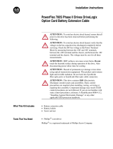
Installation Instructions
Compact I/O Cable for
DriveLogix5730 Controller
(Cat. No. 20D-DL2-CR3, 20D-DL2-CL3)
Inside ...
For More Information .............................. 2
Hazardous Location Considerations ........ 3
Overview ................................................ 4
Cable Types and Length .......................... 4
System Configurations ............................ 5
Installation .............................................. 6
Allen-Bradley Motors

2 Compact I/O Cable for DriveLogix5730 Controller
Publication 20D-IN008A-EN-P - April 2004
For More Information
For Refer to this Document Pub. No.
Information on how to install and use
your 1769-ADN Adapter
Compact
TM
I/O 1769-ADN DeviceNet Adapter
Installation Instructions
1769-IN001
Installation guides for 1769 Discrete
Compact I/O module 1769-IA8I
Compact 1769-IA8I Individually Isolated 120V ac
Input Module
1769-IN012
Installation guides for 1769 Discrete
Compact I/O module 1769-IA16
Compact 1769-IA16 120V ac Input Module
Installation Instructions
1769-IN006
Installation guides for 1769 Discrete
Compact I/O module 1769-OW8
Compact 1769-OW8 AC/DC Relay Output Module
Installation Instructions
1769-IN051
Installation guides for 1769 Discrete
Compact I/O module 1769-OW8I
Compact 1769-OW8I Individually Isolated
AC/DC Relay Output Module
1769-IN053
Installation guides for 1769 Discrete
Compact I/O module 1769-IQ16
Compact 1769-IQ16 24V dc Sink/Source Input
Module Installation Instructions
1769-IN007
Installation guides for 1769 Discrete
Compact I/O module 1769-OB16
Compact 1769-OB16 Solid State 24V dc Source
Output Module Installation Instructions
1769-IN054
Installation guides for 1769 Discrete
Compact I/O module 1769-OB16P
Compact 1769-OB16P Solid State 24V dc Source
Output Module Installation Instructions
1769-IN052
Installation guides for 1769 Discrete
Compact I/O module 1769-OA8
Compact 1769-OA8 100 to 240V ac Solid State
Output Module Installation Instructions
1769-IN055
Installation guides for 1769 Discrete
Compact I/O module 1769-OV16
Compact 1769-OV16 Solid State 24V dc Sink Output
Module Installation Instructions
1769-IN056
Installation guides for 1769 Discrete
Compact I/O module 1769-IQ6XOW4
Compact 1769-IQ6XOW4 24V dc Sink/Source Input
AC/DC Relay Output Module Installation Instructions
1769-IN050
Installation guides for 1769 Discrete
Compact I/O module 1769-IM12
Compact 1769-IM12 240V ac Input Module
Installation Instructions
1769-IN011
Installation guides for 1769 Analog
Compact I/O module 1769-IF4
Compact 1769-IF4 Analog Input Module Installation
Instructions
1769-IN048
Installation guides for 1769 Analog
Compact I/O module 1769-OF2
Compact 1769-OF2 Analog Output Module
Installation Instructions
1769-IN049
Installation guides for 1769 Analog
Compact I/O module 1769-IF4XOF2
* For Series B DeviceNet adapters only
Compact 1769-IF4XOF2 Combination Analog Module
Installation Instructions
1769-IN057
Information on how to install and use
your 1769-IF4XOF2 module
Compact 1769-IF4XOF2 8-Bit Low-Resolution Analog
I/O Combination Module User Manual
1769-UM008
Installation guides for 1769 High Speed
Counter module 1769-HSC
* For Series B DeviceNet adapters only
Compact 1769-HSC High Speed Counter Module
Installation Instructions
1769-IN030
Installation guides for 1769
Thermocouple/mV module 1769-IT6
Compact 1769-IT6 Thermocouple/mV Input Module
Installation Instructions
1769-IN026

Compact I/O Cable for DriveLogix5730 Controller 3
Publication 20D-IN008A-EN-P - April 2004
If you would like a manual, you can:
• download a free electronic version from the internet:
www.ab.com/manuals/dr or www.theautomationbookstore.com
• purchase a printed manual by:
– contacting your local distributor or Rockwell Automation representative
– visiting www.theautomationbookstore.com and placing your order
– calling 1.800.963.9548 (USA/Canada) or
001.330.725.1574 (Outside USA/Canada)
Hazardous Location Considerations
This product must be installed in an enclosure. This equipment is suitable for use in Class I,
Division 2, Groups A, B, C, D or non-hazardous locations only. The following
ATTENTION statement applies to use in hazardous locations.
EXPLOSION HAZARD
• Substitution of components may impair suitability for Class I,
Division 2.
• Do not replace components or disconnect equipment unless power
has been switched off or the area is known to be non-hazardous.
• Do not connect or disconnect components unless power has been
switched off or the area is known to be non-hazardous.
• All wiring must comply with N.E.C. article 501-4(b).
For Refer to this Document Pub. No.
Information on how to install and use
your 1769-IT6 module
Compact 1769-IT6 Thermocouple/mV Input Module
User Manual
1769-UM004
Installation guides for 1769
RTD/resistance module 1769-IR6
Compact 1769-IR6 RTD/Resistance Input Module
Installation Instructions
1769-IN027
Information on how to install and use
your 1769-IR6 module
Compact 1769-IR6 RTD/Resistance Input Module
User Manual
1769-UM005
Installation guides for 1769 power
supplies
Compact 1769 Expansion I/O Power Supplies
Installation Instructions
1769-IN028
Installation guides for 1769 cables Compact I/O Communication Bus Expansion Cables
Installation Instructions
1769-IN014
Installation guides for 1769 end caps and
terminators
Compact I/O End Caps/Terminators Installation
Instructions
1769-IN015
ATTENTION
!
Allen-Bradley Motors

4 Compact I/O Cable for DriveLogix5730 Controller
Publication 20D-IN008A-EN-P - April 2004
Overview
The 20D-DL2-CR3 and 20D-DL2-CL3 cables allow you to connect a DriveLogix5730 Phase
II controller to a bank of Compact I/O. A maximum of two banks of I/O can be used a
DriveLogix5730 Phase II controller. Each bank requires its own power supply.
See System
Configurations on page 5.
Cable Types and Length
Cables for Connecting Controllers to I/O Banks
Catalog Number Cable Type
Length
(1)
(1)
Approximate cable length is measured from end-to-end of the cable only.
20D-DL2-CL3 Controller-to-left bank expansion 3.28 ft. (1 m)
20D-DL2-CR3 Controller-to-right bank expansion 3.28 ft. (1 m)
15 mm
(0.59 in.)
32 mm
(1.26 in.)
18 mm
(0.71 in.)
118 mm
(4.65 in.)
118 mm
(4.65 in.)
20D-DL2-CL2 20D-DL2-CR2
Cables for Connecting I/O Banks to I/O Banks
Catalog Number Cable Type
Length
(1)
(1)
Approximate cable length is measured from end-to-end of the cable only.
1769-CLL1 Left bank-to-left bank expansion 1 ft. (305 mm)
1769-CLL3 Left bank-to-left bank expansion 3.28 ft. (1 m)
1769-CRR1 Right bank-to-right bank expansion 1 ft. (305 mm)
1769-CRR3 Right bank-to-right bank expansion 3.28 ft. (1 m)
1769-CRL1 Right bank-to-left bank expansion 1 ft. (305 mm)
1769-CRL3 Right bank-to-left bank expansion 3.28 ft. (1 m)

Compact I/O Cable for DriveLogix5730 Controller 5
Publication 20D-IN008A-EN-P - April 2004
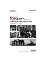
System Configurations
The following illustration show examples of four valid system setups.
Bank 1
1
I/O Slot Number
1769 I/O
1769 Power Supply
1769 I/O
PowerFlex 700S Drive
DriveLogix
2
1769 I/O
Bank 1
Bank 2
1769-CRL3
1769-CRL3
1769 I/O
1769 Power Supply
1769 I/O
1769 End Cap
20D-DL2-CL2
1769 I/O
1769 Power Supply
PowerFlex 700S Drive
DriveLogix
1
I/O Slot Number
2
3
4
20D-DL2-CL2
DriveLogix
PowerFlex 700S Drive
1769 Power Supply
1769 I/O
1769 End Cap
20D-DL2-CR2
1769 I/O
Bank 1
I/O Slot Number
DriveLogix
PowerFlex 700S Drive
1769 Power Supply
1769 I/O
1769-CRl3
20D-DL2-CR2
1769 I/O
Bank 1
I/O Slot Number
2
1
2
1
1769 Power Supply
1769 I/O
1769 End Cap
1769-CRl3
1769 I/O
Bank 2
4
3
Allen-Bradley Motors

6 Compact I/O Cable for DriveLogix5730 Controller
Publication 20D-IN008A-EN-P - April 2004
Installation
Remove Power
To avoid an electric shock hazard, verify that the voltage on the bus
capacitors has discharged before performing any work on the drive.
Measure the DC bus voltage at the +DC & –DC terminals of the
Power Terminal Block. The voltage must be zero.
HOT surfaces can cause severe burns. Do not touch the heatsink
surface during operation of the drive. After disconnecting power
allow time for cooling.
Remove power before making or breaking cable connections. When
you remove or insert a cable connector with power applied, an
electrical arc may occur. An electrical arc can cause personal injury or
property damage by:
• sending an erroneous signal to your system’s field devices,
causing unintended machine motion
• causing an explosion in a hazardous environment
Electrical arcing causes excessive wear to contacts on both the
module and its mating connector. Worn contacts may create electrical
resistance.
Electrostatic discharge can damage integrated circuits or
semiconductors if you touch bus connector pins or the terminal
block. Follow these guidelines when handling 1769 Compact I/O
components:
• Touch a grounded object to discharge static potential.
• Wear an approved wrist-strap grounding device.
• Do not touch the bus connector or connector pins.
• Do not touch circuit components inside the module.
• If available, use a static-safe workstation.
• When not in use, keep cables in static shield packaging.
ATTENTION
!

Compact I/O Cable for DriveLogix5730 Controller 7
Publication 20D-IN008A-EN-P - April 2004
What You Need to Do
❐ Step 1: Remove power from drive and Compact I/O
❐ Step 2: Remove the control cassette from the drive and the cover
from the control cassette
❐ Step 3: Install the controller end of the cable
❐ Step 4: Replace the cover and control cassette
❐ Step 5: Connect the Compact I/O end of the cable
Allen-Bradley Motors

8 Compact I/O Cable for DriveLogix5730 Controller
Publication 20D-IN008A-EN-P - April 2004
Step 1: Removing Power from Drive and Compact I/O
To avoid an electric shock hazard, verify that the voltage on the bus
capacitors has discharged before performing any work on the drive.
Measure the DC bus voltage at the +DC & –DC terminals of the
Power Terminal Block. The voltage must be zero.
Remove power before making or breaking cable connections. When
you remove or insert a cable connector with power applied, an
electrical arc may occur. An electrical arc can cause personal injury or
property damage by:
• sending an erroneous signal to your system’s field devices,
causing unintended machine motion
• causing an explosion in a hazardous environment
Electrical arcing causes excessive wear to contacts on both the
module and its mating connector. Worn contacts may create electrical
resistance.
L1 L2 L3
O
I
ATTENTION
!

Compact I/O Cable for DriveLogix5730 Controller 9
Publication 20D-IN008A-EN-P - April 2004
Step 2: Removing the Control Cassette from the Drive and the Covers from
the Cassette
BR1
B
R
2
D
C
+
D
C
-
PE
U/T1
V/T2
W/T3
R/L1
L2
B
(x2)
C
A
=
(x2)
(x3)
A
B
=
Proper tightening
torque for reassembly
is 6 lb.-in.
Removing the Cassette
Task Description
Open the door of the power
structure and disconnect the
cables that connect to the main
board
Loosen screws on face of cassette
Remove the cassette
A
B
C
Removing the Side Covers
Task Description
Loosen screws on face of front
cover and remove the cover
Loosen screws on side of rear
cover and remove the cover
A
B
Allen-Bradley Motors

10 Compact I/O Cable for DriveLogix5730 Controller
Publication 20D-IN008A-EN-P - April 2004
Step 3: Installing the Controller End of the Cable
D
D
D
D
A
A
B
C
C
=
Use cable tie to anchor cable
to slots on this flange for
strain relief
Task Description
Install clips on controller end of cable
Plug controller end of cable into mating
connector on the Logix Expansion Board
Install and tighten screws (6 lb.-in.)
Route and secure cable
A
B
C
D
Step 4: Replacing the Cover and Control Cassette
The procedure for replacing the cover and control cassette is the reverse of removing these
components.
Refer to Step 2: Removing the Control Cassette from the Drive and the Covers
from the Cassette on page 9.

Compact I/O Cable for DriveLogix5730 Controller 11
Publication 20D-IN008A-EN-P - April 2004
Step 5: Installing the Compact I/O End of the Cable
When energized bus connections break in hazardous environments,
resulting sparks can cause explosions.
Risk of personal injury and/or equipment damage exists.
Securely lock the bus connectors (tasks D and E below) to avoid this
hazard.
2
3
A D
1
B
C
E
1
C
B
2
3
Left Cover
Right Cover
Task Description
Unlock the Bus Lever on the I/O module accepting the cable cover by pushing
the lever back and then right
Align both of the cable cover’s tongues (1) with the grooves (2) on the side of the
I/O module
Slide the cable cover back onto the module until the bus connectors (3) are
aligned
Lock the Bus Lever on the I/O module by pushing the lever back and then left
until locked
On a right-hand cable cover, lock the Bus Lever by pushing the lever back to
the left until locked
A
B
C
D
E
=
=
ATTENTION
!
Allen-Bradley Motors

Each I/O bank requires its own power supply. The 1769 cables extend the
1769 communication bus, but do not extend bus power.
Specifications
Approximate Shipping
Weight (with carton)
3-foot cables: 350 g (0.77lbs.)
Storage Temperature -40°C to +85°C (-40°F to +185°F)
Operating Temperature 0°C to +60°C (32°F to +140°F)
Operating Humidity 5% to 95% non-condensing
Operating Altitude 2000 meters (6561 feet)
Vibration Operating: 10 to 500 Hz, 5G, 0.030 inches maximum peak-to-peak
Relay Operation: 2G
Shock Operating: 30G panel mounted (20G DIN rail mounted)
Relay Operation: 7.5G panel mounted (5G DIN rail mounted)
Non-Operating: 40G panel mounted (30G DIN rail mounted)
Agency Certification C-UL certified (under CSA C22.2 No. 142)
UL 508 listed
CE compliant for all applicable directives
Hazardous Environment
Class
Class I, Division 2, Hazardous Location, Groups A, B, C, D
(UL 1604, C-UL under CSA C22.2 No. 213)
Publication 20D-IN008A-EN-P - April 2004 PN 335729-P01
Copyright © 2004 Rockwell Automation. All rights reserved. Printed in the U.S.A.
www.rockwellautomation.com
Corporate Headquarters
Rockwell Automation, 777 East Wisconsin Avenue, Suite 1400, Milwaukee, WI, 53202-5302 USA, Tel: (1) 414.212.5200, Fax: (1) 414.212.5201
Headquarters for Allen-Bradley Products, Rockwell Software Products and Global Manufacturing Solutions
Americas: Rockwell Automation, 1201 South Second Street, Milwaukee, WI 53204-2496 USA, Tel: (1) 414.382.2000, Fax: (1) 414.382.4444
Europe/Middle East/Africa: Rockwell Automation SA/NV, Vorstlaan/Boulevard du Souverain 36, 1170 Brussels, Belgium, Tel: (32) 2 663 0600, Fax: (32) 2 663 0640
Asia Pacific: Rockwell Automation, 27/F Citicorp Centre, 18 Whitfield Road, Causeway Bay, Hong Kong, Tel: (852) 2887 4788, Fax: (852) 2508 1846
Headquarters for Dodge and Reliance Electric Products
Americas: Rockwell Automation, 6040 Ponders Court, Greenville, SC 29615-4617 USA, Tel: (1) 864.297.4800, Fax: (1) 864.281.2433
Europe/Middle East/Africa: Rockwell Automation, Brühlstraße 22, D-74834 Elztal-Dallau, Germany, Tel: (49) 6261 9410, Fax: (49) 6261 17741
Asia Pacific: Rockwell Automation, 55 Newton Road, #11-01/02 Revenue House, Singapore 307987, Tel: (65) 6356-9077, Fax: (65) 6356-9011
U.S. Allen-Bradley Drives Technical Support
Tel: (1) 262.512.8176, Fax: (1) 262.512.2222, Email: support@drives.ra.rockwell.com, Online: www.ab.com/support/abdrives
TIP
/