2
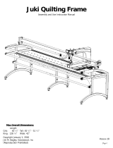
Frame Specications .......................................................................................3
Included Parts & Tools
....................................................................................4
Full Frame Assembly
.......................................................................................8
Step 1 - Setting the Frame Height
.........................................................................................................9
Step 2 - Building the Frame Table ..................................................................................................... 11
Step 3 - Installing the Tracks .............................................................................................................. 15
Step 4 - Assembling the Rail Supports .............................................................................................. 18
Step 5 - Installing the Bottom Carriage ............................................................................................ 19
Step 6 - Installing the Quilting Machine .......................................................................................... 21
Step 7 - Leveling the Frame ................................................................................................................ 23
Step 8 - Installing the Rails ................................................................................................................. 25
Step 9 - Assembling the Handwheel .................................................................................................. 29
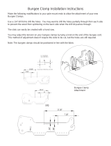
Step 10 - Installing the Bungee Clamps ............................................................................................ 30
Step 11 - Adjusting the Rails .............................................................................................................. 31
Step 12 - Installing the Velcro Tape .................................................................................................. 33
Step 13 - Installing Leader Cloth ...................................................................................................... 36
Crib Frame Assembly
..................................................................................... 38
Step 1 - Setting the Frame Height
...................................................................................................... 39
Step 2 - Building the Frame Table ..................................................................................................... 40
Step 3 - Installing the Tracks .............................................................................................................. 43
Step 4 - Assembling the Rail Supports .............................................................................................. 45
Step 5 - Installing the Bottom Carriage ............................................................................................ 46
Step 6 - Installing the Quilting Machine .......................................................................................... 48
Step 7 - Leveling the Frame ................................................................................................................ 50
Step 8 - Installing the Rails ................................................................................................................. 52
Step 9 - Assembling the Handwheel .................................................................................................. 55
Step 10 - Installing the Bungee Clamps ............................................................................................ 56
Step 11 - Setting the Rail Distances ................................................................................................... 57
Step 12 - Installing the Velcro Tape .................................................................................................. 59
Step 13 - Installing Leader Cloth ...................................................................................................... 62
Using Your Frame
..........................................................................................64
Sizing the Quilt Backing and Batting
................................................................................................ 65
Attaching the Fabric ............................................................................................................................ 66
Using the Channel Locks .................................................................................................................... 70
Contents