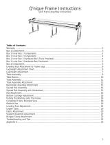
Grace Company Continuum II Frame Operating instructions

Type
Operating instructions

This manual is also suitable for

Grace Company The Continuum II Frame is a versatile accessory designed to enhance your quilting experience. With its adjustable height and easy installation, it allows you to create beautiful quilts of various sizes. It is compatible with Q'nique 15, 19, and 21 machines and is available in 4, 5, 8, 10, and 12-foot lengths to accommodate your specific needs.

Grace Company The Continuum II Frame is a versatile accessory designed to enhance your quilting experience. With its adjustable height and easy installation, it allows you to create beautiful quilts of various sizes. It is compatible with Q'nique 15, 19, and 21 machines and is available in 4, 5, 8, 10, and 12-foot lengths to accommodate your specific needs.

1
Copyright August 31, 2020
Grace Company
(Reproduction Prohibited)
Version 1.0
Accessory Idler Rail Assembly & Use
2
2 ft Rail
Section
8 Foot
Rail
Coupler
Non-ratcheting
Rail Section
Non-ratcheting
Rail Section
Non-ratcheting
Rail Section
Non-ratcheting
Rail Section
Non-ratcheting
Rail Section
Non-ratcheting
Rail Section
Non-ratcheting
Rail Section
Rail
Coupler
Rail
Coupler
Rail
Coupler
Rail
Coupler
Rail
Coupler
2 ft Rail
Section
2 ft Rail
Section
5 ft Rail
Section
Non-ratcheting
Rail End
Non-ratcheting
Rail End
Non-ratcheting
Rail End
10 Foot
12 Foot
4 Foot
5 Foot
Idler Rail Configurations
Idler Rail Congurations ...............................................................................................................2
Included Parts & Tools .................................................................................................................3
8 Foot Frame ..............................................................................................................................4
10 Foot Frame ............................................................................................................................9
12 Foot Frame ..........................................................................................................................15
4 Foot ......................................................................................................................................21
5 Foot ......................................................................................................................................25
Setting the Rail Height ...............................................................................................................29
Installing the Fabric ................................................................................................................... 30
Contents
3
Rail Coupler (x3)
CNT-08-11865
2 ft Rail Section (x2)
ME T-04-11397
Non-Ratcheting Rail Section 4 ft (x2)
CII- 09-14638
Why does my Accessory Idler Rail come with so many pieces?
To accommodate the three available sizes of Continuum 2 frame (8 foot, 10 foot, and 12 foot), the
Continuum 2 Idler Rail kit you’ve purchased may include more parts than your frame requires. Do
not discard the extra parts; you may need them if you choose to upgrade your frame in the future.
CII- 04 -14510 CII- 04 -14601
Included Parts & Tools
Please make sure all pieces are included in your kit.
Left Idler Rail Mount
Right Idler
Rail Mount
HDW-03-10167
Allen Wrench 4 mm
14
17
HDW-03-14608
HDW-03-14873
3-Armed Knob (x2)
Shoulder Bolt
M6 (x2)
4
8 Foot Frame
Parts & Tools Needed:
Non-ratcheting rail Section 4 ft (x2)
Rail Coupler Allen Wrench 4 mm
14
17
Left Idler Rail Mount
Right Idler
Rail Mount
3-Armed Knob (x2)
Shoulder Bolt
M6 (x2)
5
Instructions
To assemble and install the idler rail on the 8 foot frame, take the following steps:
Slide a rail coupler into one of the non-ratcheting rail sections. Line up the screws on the
coupler with the holes on the rail.
1
Rail Screw Holes
Non-ratcheting rail
Section
Rail Coupler
3
Slide the remaining non-ratcheting rail section onto the other side of the rail coupler.
Use a 4 mm Allen wrench to turn the screws inside the rail counter-clockwise until they press
rmly against the rail.
2
Non-ratcheting rail
Section
Idler Rail - 8 Foot Frame
6
Press in the levers on each of the take-up rail arms, then fully raise the take-up rail.
Loosen the 3-armed knobs on the take up rail arms on both sides of the frame.
Align the holes with the coupler screws and turn the screws counter-clockwise with the 4 mm
Allen wrench until they press rmly against the inside of the rail.
4
Idler Rail - 8 Foot Frame
5
6
7
Pass the idler rail through the throat of the machine and place each end into the mounts.
The mount holding the idler rail is installed on two of the 3 holes on the take-up rail arm.
Choose whether to install the mount on the top two or bottom two holes by considering the size
of your machine.
7
9
Use the shoulder bolt and 4 mm Allen wrench to screw the idler rail mounts to each arm.
8
Idler Rail - 8 Foot Frame
Q’nique 15, 19
Installation Spot
Q’nique 21
Installation Spot
Shoulder Bolt
M6
Shoulder Bolt
M6
Left Idler Rail
Mount
Right Idler Rail
Mount
8
Push in on the mount and install the 3-armed knob. To remove the frame in the future,
simply loosen the 3-armed knob and lift the rail out of the mounts.
10
3-Armed Knob
3-Armed Knob
Idler Rail - 8 Foot Frame
Set the rail height. For instructions, see page 29.
9
2 ft Rail Section
Left Idler Rail Mount
Right Idler
Rail Mount
3-Armed Knob (x2)
Shoulder Bolt
M6 (x2)
10 Foot Frame
Parts & Tools Needed:
Non-ratcheting rail Section 4 ft (x2)
Rail Coupler (x2)
Allen Wrench 4 mm
14
17
10
Instructions
To assemble and install the idler rail on the 10 foot frame, take the following steps:
Slide a rail coupler into one of the non-ratcheting rail sections. Line up the screws on the
coupler with the holes on the rail.
1
Rail Screw Holes
Non-ratcheting rail
Section
Rail Coupler
2
3
Slide one of the 2 ft rail sections onto the other side of the rail coupler.
2 ft Rail Section
Use a 4 mm Allen wrench to turn the screws inside the rail counter-clockwise until they press
rmly against the rail.
Idler Rail - 10 Foot Frame
11
6
Now insert a second coupler into the 2 ft rail section.
5
Rail Coupler
Align the holes with the coupler screws and turn the screws counter-clockwise with the 4 mm
Allen wrench until they press rmly against the inside of the rail.
4
Once again, turn the screws counter-clockwise with the 4 mm Allen wrench until the rail and
coupler are snug.
Idler Rail - 10 Foot Frame
12
Install the remaining non-ratcheting rail section onto the other side of the rail coupler. Use
the 4 mm Allen wrench to turn the coupler screws counter-clockwise.
7
Non-ratcheting rail
Section
Press in the levers on each of the take-up rail arms, then fully raise the take-up rail.
Loosen the 3-armed knobs on the take up rail arms on both sides of the frame.
8
9
Idler Rail - 10 Foot Frame
13
The mount holding the idler rail is installed on two of the 3 holes on the take-up rail arm.
Choose whether to install the mount on the top two or bottom two holes by considering the size
of your machine.
10
12
11
Q’nique 15, 19
Installation Spot
Q’nique 21
Installation Spot
Idler Rail - 10 Foot Frame
Pass the idler rail through the throat of the machine and place each end into the mounts.
Use the shoulder bolt and 4 mm Allen wrench to screw the idler rail mounts to each arm.
Shoulder Bolt
M6
Shoulder Bolt
M6
Left Idler Rail
Mount
Right Idler Rail
Mount
14
13
Idler Rail - 10 Foot Frame
Push in on the mount and install the 3-armed knob. To remove the frame in the future,
simply loosen the 3-armed knob and lift the rail out of the mounts.
Set the rail height. For instructions, see page 29.
3-Armed Knob
3-Armed Knob
15
12 Foot Frame
Parts & Tools Needed:
Non-ratcheting rail Section 4 ft (x2)
Rail Coupler (x3)
Allen Wrench 4 mm
14
17
2 ft Rail Section (x2)
Left Idler Rail Mount
Right Idler
Rail Mount
3-Armed Knob (x2)
Shoulder Bolt
M6 (x2)
16
Instructions
To assemble and install the idler rail on the 12 foot frame, take the following steps:
Slide a rail coupler into one of the non-ratcheting rail sections. Line up the screws on the
coupler with the holes on the rail.
1
Rail Screw Holes
Non-ratcheting rail
Section
Rail Coupler
2
3
Slide one of the 2 ft rail sections onto the other side of the rail coupler.
2 ft Rail Section
Use a 4 mm Allen wrench to turn the screws inside the rail counter-clockwise until they press
rmly against the rail.
Idler Rail - 12 Foot Frame
17
6
Now insert a second coupler into the 2 ft rail section.
5
Rail Coupler
Align the holes with the coupler screws and turn the screws counter-clockwise with the 4 mm
Allen wrench until they press rmly against the inside of the rail.
4
Once again, turn the screws counter-clockwise with the 4 mm Allen wrench until the rail and
coupler are snug.
Idler Rail - 12 Foot Frame
18
Install a second 2 ft rail section onto the rail coupler. Turn the coupler screws counter-clockwise
with the 4 mm Allen wrench to x the rail section in place.
7
2 ft Rail Section
Slide the third rail coupler into the free end of the 2 ft rail section. Use the 4 mm Allen wrench
to turn the screws counter-clockwise until the rail coupler is held rmly in place.
8
Rail Coupler
Install the remaining non-ratcheting rail section onto the other side of the rail coupler. Use
the 4 mm Allen wrench to turn the coupler screws counter-clockwise.
9
Non-ratcheting rail
Section
Idler Rail - 12 Foot Frame
19
Press in the levers on each of the take-up rail arms, then fully raise the take-up rail.
Loosen the 3-armed knobs on the take up rail arms on both sides of the frame.
10
11
The mount holding the idler rail is installed on two of the 3 holes on the take-up rail arm.
Choose whether to install the mount on the top two or bottom two holes by considering the size
of your machine.
12
Q’nique 15, 19
Installation Spot
Q’nique 21
Installation Spot
Idler Rail - 12 Foot Frame
20
14
13
15
Idler Rail - 12 Foot Frame
Pass the idler rail through the throat of the machine and place each end into the mounts.
Push in on the mount and install the 3-armed knob. To remove the frame in the future,
simply loosen the 3-armed knob and lift the rail out of the mounts.
Use the shoulder bolt and 4 mm Allen wrench to screw the idler rail mounts to each arm.
Set the rail height. For instructions, see page 29.
Shoulder Bolt
M6
Shoulder Bolt
M6
Left Idler Rail
Mount
Right Idler Rail
Mount
3-Armed Knob
3-Armed Knob
  • Page 1 1
  • Page 2 2
  • Page 3 3
  • Page 4 4
  • Page 5 5
  • Page 6 6
  • Page 7 7
  • Page 8 8
  • Page 9 9
  • Page 10 10
  • Page 11 11
  • Page 12 12
  • Page 13 13
  • Page 14 14
  • Page 15 15
  • Page 16 16
  • Page 17 17
  • Page 18 18
  • Page 19 19
  • Page 20 20
  • Page 21 21
  • Page 22 22
  • Page 23 23
  • Page 24 24
  • Page 25 25
  • Page 26 26
  • Page 27 27
  • Page 28 28
  • Page 29 29
  • Page 30 30
  • Page 31 31
  • Page 32 32
  • Page 33 33

Grace Company Continuum II Frame Operating instructions

Type
Operating instructions
This manual is also suitable for

Grace Company The Continuum II Frame is a versatile accessory designed to enhance your quilting experience. With its adjustable height and easy installation, it allows you to create beautiful quilts of various sizes. It is compatible with Q'nique 15, 19, and 21 machines and is available in 4, 5, 8, 10, and 12-foot lengths to accommodate your specific needs.

Ask a question and I''ll find the answer in the document

Finding information in a document is now easier with AI