Maxon 581245 Hardware Reference Manual
- Type
- Hardware Reference Manual
This manual is also suitable for
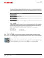
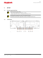
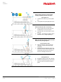
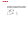
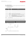
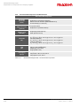
Maxon 581245 is a plug-in extension card for EPOS4 positioning controllers that provides complete EtherCAT communication capability. It can be used with either an EPOS4 encased housing variant or an EPOS4 Module with full EtherCAT functionality. The card supports high-speed data transfer and real-time communication, making it suitable for demanding motion control applications. It also features EtherCAT status and port LEDs for easy diagnostics and troubleshooting.
Maxon 581245 is a plug-in extension card for EPOS4 positioning controllers that provides complete EtherCAT communication capability. It can be used with either an EPOS4 encased housing variant or an EPOS4 Module with full EtherCAT functionality. The card supports high-speed data transfer and real-time communication, making it suitable for demanding motion control applications. It also features EtherCAT status and port LEDs for easy diagnostics and troubleshooting.


-
 1
1
-
 2
2
-
 3
3
-
 4
4
-
 5
5
-
 6
6
-
 7
7
-
 8
8
-
 9
9
-
 10
10
-
 11
11
-
 12
12
-
 13
13
-
 14
14
-
 15
15
-
 16
16
-
 17
17
-
 18
18
-
 19
19
-
 20
20
-
 21
21
-
 22
22
-
 23
23
-
 24
24
-
 25
25
-
 26
26
-
 27
27
-
 28
28
-
 29
29
-
 30
30


Maxon 581245 Hardware Reference Manual
- Type
- Hardware Reference Manual
- This manual is also suitable for
Maxon 581245 is a plug-in extension card for EPOS4 positioning controllers that provides complete EtherCAT communication capability. It can be used with either an EPOS4 encased housing variant or an EPOS4 Module with full EtherCAT functionality. The card supports high-speed data transfer and real-time communication, making it suitable for demanding motion control applications. It also features EtherCAT status and port LEDs for easy diagnostics and troubleshooting.
Ask a question and I''ll find the answer in the document
Finding information in a document is now easier with AI