Page is loading ...

MICRO-EPSILON Eltrotec GmbH
Manfred-Wörner-Straße 101 · 73037 Göppingen / Germany
Tel. +49 (0) 7161 / 98872-300 · Fax +49 (0) 7161 / 98872-303
[email protected] · www.micro-epsilon.com
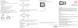
EDU190-4 Pro
EDU190-7 Pro
Operating Instructions
optoCONTROL EDU190

MICRO-EPSILON
Eltrotec GmbH
Manfred-Wörner-Straße 101
73037 Göppingen / Germany
Tel. +49 (0) 7161 / 98872-300
Fax +49 (0) 7161 / 98872-303
www.micro-epsilon.com
Digital Display

optoCONTROL EDU190
Contents
1. Safety ........................................................................................................................................ 5
1.1 Symbols Used ................................................................................................................................................. 5
1.2 Warnings .......................................................................................................................................................... 5
1.3 Notes on CE Marking ...................................................................................................................................... 6
1.4 Intended Use ................................................................................................................................................... 7
1.5 Proper Environment ......................................................................................................................................... 7
2. Functional Principle, Technical Data ...................................................................................... 8
2.1 Functional Principle ........................................................................................................................................ 8
2.2 Technical Data ................................................................................................................................................. 9
3. Delivery ................................................................................................................................... 11
3.1 Unpacking/Included in Delivery .................................................................................................................... 11
3.2 Storage .......................................................................................................................................................... 11
4. Installation and Assembly ...................................................................................................... 12
4.1 Pin Assignment .............................................................................................................................................. 14
4.2 Cables ............................................................................................................................................................ 15
4.3 Connections for optoCONTROL ODC1202 / ODC1220 ............................................................................... 16
4.4 Connections for optoCONTROL ODC2600 / ODC2500 ............................................................................... 17
4.5 Connections for optoCONTROL ODC2520 ................................................................................................... 18
4.6 Displays ......................................................................................................................................................... 19
5. Software .................................................................................................................................. 20
5.1 Basic Settings ................................................................................................................................................ 20
5.2 Software ......................................................................................................................................................... 22
5.2.1 Settings ......................................................................................................................................... 22
5.2.2 Display Measurement Value ......................................................................................................... 25
5.2.3 Sensor Information ....................................................................................................................... 27
6. Liability for Material Defects .................................................................................................. 28
7. Service, Repair ...................................................................................................................... 28
8. Decommissioning, Disposal .................................................................................................. 28

optoCONTROL EDU190
Appendix
A 1 Accessories ............................................................................................................................ 29
A 1.1 Connecting the Digital Display to ODC1202 / ODC1220 .............................................................................. 29
A 1.2 Connecting the Digital Display to ODC2500 / ODC2600 .............................................................................. 29
A 1.3 Connecting the Digital Display to ODC2520 ................................................................................................. 29

Page 5
Safety
optoCONTROL EDU190
1. Safety
System operation assumes knowledge of the operating instructions.
1.1 Symbols Used
The following symbols are used in these operating instructions:
WARNUNG
Indicates a hazardous situation which, if not avoided, could result in death or seri-
ous injury.
Indicates a hazardous situation which, if not avoided, may result in minor or mode-
rate injury.
Indicates a situation that may result in property damage if not avoided.
Indicates a user action.
i
Indicates a tip for users.
Measure
Indicates hardware or a software button/menu.
1.2 Warnings
Avoid use in Ex areas.
> Death or injury due to explosion hazard
Liquids, metal swarf and wire parts may not enter the openings of the digital display under any circumstanc-
es.
> Electric shock, risk of fire
The digital display liquid contains a powerful irritant. In case of skin contact, wash immediately with plenty of
water. In case of eye contact, hold the eye open, flush with plenty of water and get medical attention.
> Risk of injury, damage to the eyes or skin
Connect the power supply according to the safety regulations for electrical equipment.
> Risk of injury, damage to or destruction of the system
WARNING

Page 6
Safety
optoCONTROL EDU190
The supply voltage must not exceed the specified limits.
> Damage to or destruction of digital display
No sharp or heavy objects should be allowed to affect the cables. Avoid folding the cables. Do not bend
more tightly than the minimum bending radius of the cables.
> Damage to or destruction of the cables, failure of the digital display
Avoid shocks and impacts to the digital display.
> Damage to or destruction of the digital display
Storing the digital display where the temperature is lower/higher than recommended in the technical data can
cause the LCD display liquid to congeal/become isotopic.
> Damage to or destruction of digital display
Avoid use in direct sunlight, strong magnetic fields, high temperatures and sudden temperature changes.
> Color alterations on the display or system failure
1.3 Notes on CE Marking
The following apply to the optoCONTROL EDU190:
- EU Directive 2014/30/EU
- EU Directive 2011/65/EU
Products which carry the CE mark satisfy the requirements of the EU directives cited and the European
harmonized standards (EN) listed therein. The EU Declaration of Conformity is available to the responsible
authorities according to EU Directive, article 10, at:
MICRO-EPSILON Eltrotec GmbH
Manfred-Wörner-Straße 101
73037 Göppingen /Germany
The measuring system is designed for use in industrial environments and meets the requirements.

Page 7
Safety
optoCONTROL EDU190
1.4 Intended Use
The optoCONTROL EDU190 digital display is designed for use in industrial and laboratory applications. It is
used to display the measurement values and parameters of all optical optoCONTROL ODC micrometers with
digital interface.
The system must only be operated within the limits specified in the technical data, see 2.2.
- The system must be used in such a way that no persons are endangered or machines and other material
goods are damaged in the event of malfunction or total failure of the sensor.
- Take additional precautions for safety and damage prevention in case of safety-related applications.
1.5 Proper Environment
- Protection class:
Front panel:
IP 66 (EDU190-4 Pro), IP 65 (EDU190-7 Pro)
Rear: IP 20
- Operating temperature: -10 ... +60 °C (+14 ... +140 °F)
- Storage temperature: -20 ... +70 °C (-4 ... +158 °F)
- Ambient pressure: Atmospheric pressure

Page 8
Functional Principle, Technical Data
optoCONTROL EDU190
2. Functional Principle, Technical Data
2.1 Functional Principle
The optoCONTROL EDU190 digital display enables measurements to be performed on semi-automated
workstations quickly and easily, while visualizing and evaluating the measured value without requiring any
additional end devices.
The digital display is compatible with all optical micrometers from Micro-Epsilon that have a digital interface.
The sensors can be connected either serially (RS232, RS422) or via Ethernet.
i
Multi-segment measurements are not possible.

Page 9
Functional Principle, Technical Data
optoCONTROL EDU190
2.2 Technical Data
Model EDU190-4 Pro EDU190-7 Pro
Display size (diagonal) 4.3 inches 7 inches
Resolution 480 x 272 pixels 800 x 480 pixels
Service life (backlight) 50,000 operating hours 20,000 operating hours
Display type TFT-LCD
System 1.0 GHz processor with 512 MB RAM
Number of digits max. 5 digits
Baud rate 115.2 kBd
Screen operation resistive (touch)
Display 1 x multicolor LED display
Serial interface RS232 or RS422
Digital interface Ethernet (RJ45 socket)
Supply voltage 18 … 32 VDC
Power consumption 12 W (24 V) 14.4 W (24 V)
Humidity 5 - 85 % (non-condensing)
Temperature
range
Storage -20 °C … +70 °C (-4 ... +158 °F)
Operation -10 °C … +60 °C (+14 ... +140 °F)
Protection class
front IP 66 IP 65
rear IP 20
Shock 15 g, semi-sinusoidal, 11 ms (IEC60068-2-27)
Vibration 1 g (IEC60068-2-6)
Certifications CE, UL 61010-2-201
Weight approx. 0.5 kg approx. 0.8 kg

Page 10
Functional Principle, Technical Data
optoCONTROL EDU190
Model EDU190-4 Pro EDU190-7 Pro
Material
Display polyester on glass, ITO film
Housing (rear) powder-coated aluminum
Frame material Autoflex EBA 180L
Installation front panel installation
Cut-out dimensions 130 x 89 mm 189 x 128 mm

Page 11
Delivery
optoCONTROL EDU190
3. Delivery
3.1 Unpacking/Included in Delivery
1 Digital display
1 Assembly instructions
1 Gender changer
4 Holding clamps for installation of digital display
Carefully remove the components of the measuring system from the packaging and ensure that the
goods are forwarded in such a way that no damage can occur.
Check the delivery for completeness and shipping damage immediately after unpacking.
If there is damage or parts are missing, immediately contact the manufacturer or supplier.
Optional accessories are available in the appendix, see A 1.
3.2 Storage
Storage temperature: -20 ... +70 °C (-4 ... +158 °F)
Humidity: 5 to 85 % (non-condensing)

Page 12
Installation and Assembly
optoCONTROL EDU190
4. Installation and Assembly
Place the digital display on a stable surface during installation.
Use the cut out dimensions in the technical data, see operating instructions.
Install the digital display into the panel cut-out.
Secure the digital display by screwing the recesses head screw clockwise, allowing the built-in bracket
to flip out and tighten against the cabinet.
Tighten the screws from 0.5 to 1.0 Nm.
4 (or 8) screws
Fig. 1 Installation of digital display
Avoid use in Ex areas.
> Death or injury due to explosion hazard
Avoid use in direct sunlight, strong magnetic fields, high temperatures and sudden temperature changes.
> Color alterations on the display or system failure
WARNING

Page 13
Installation and Assembly
optoCONTROL EDU190
100 (3.94)*
104 (4.09)
145
(5.71)
43
(1.69)
50
(1.97)*
50
(1.97)*
100 (3.94)*
100 (3.94)*
100
(3.94) *
204
(8.03)
143 (5.63)
43
(1.69)
50
(1.97)*
50
(1.97)*
100
(3.94) *
100
(3.94) *
Cut out dimensions for the installation of the digital display:
130 x 89 mm (5.12 x 3.50 inches)
Cut out dimensions for the installation of the digital display:
189 x 128 mm (7.44 x 5.04 inches)
Fig. 2 Dimensional drawing optoCONTROL EDU190-4 Pro,
dimensions in mm (inches), not to scale
Fig. 3 Dimensional drawing optoCONTROL EDU190-7 Pro,
dimensions in mm (inches), not to scale

Page 14
Installation and Assembly
optoCONTROL EDU190
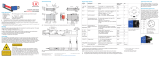
4.1 Pin Assignment
Depending on the available sensor interface, the optoCONTROL ODC sensors with digital interface can be
connected to this EDU190 digital display either via LAN connection or COM connection.
Power supply
LAN connection COM connection
RS422 / RS232
Item Connection Description
1 Power supply +24 VDC (18 ... 32 VDC)
2 LAN A 1 x 10/100 Base-T (RJ-45 shielded)
3 COM RS422 or RS232
Fig. 4 Ports on the display bottom side
Please refer to the operating instructions of the respectively connected sensor for details on the pin assign-
ment.
Supply voltage:
- Digital display: +24 VDC (18 - 32 VDC)
- Sensor: The exact values can be found in the operating instructions of the respectively con-
nected sensor.
Power consumption:
- EDU190-4 Pro: 12 W (24 V)
- EDU190-7 Pro: 14.4 W (24 V)

Page 15
Installation and Assembly
optoCONTROL EDU190
Cable PC190-2 Pin Color Power supply
PIN + white +24 V
PIN - brown (-)GND
Fig. 5 Pin assignment PC190-2
Switch off the power supply when you exit the display program or switch off the sensor.
Switch on the power supply again when you restart the display program or the sensor.
4.2 Cables
Sensor Required cables Article no. Interface Adapter connec-
tion
Remarks
ODC2520 PC/SC2520-3/IF2008
und PC/SC190-3
29011014/
29011205
RS422 9-pin /
15-pin SubD
IF2008 + power
Power, no fur-
ther signals
ODC2500 SCD2500-3-3/RS232 2901121 RS232 9-pin /
25-pin SubD +
open braids
Other
signals
ODC2600
ODC2500
SCD2500-3/EDU190
RS422
29011211 RS422
9-pin /
25-pin SubD
Display only
ODC2600
ODC2500 SCD2500-3/EDU190/
RS232
29011208 RS232 9-pin /
25-pin SubD
ODC2600
ODC2520 SCD2520-3 2901925 Ethernet RJ45
ODC1202 SCD1202-x-RS232 2901371 RS232 9-pol. SubD
ODC1220
EDU190 PC190-2 29011209 Power Green
connector
24 VDC power
supply
Please refer to the individual operating instructions of the corresponding Micro-Epsilon sensors for cables
and connections required to operate the individual sensors.

Page 16
Installation and Assembly
optoCONTROL EDU190
4.3 Connections for optoCONTROL ODC1202 / ODC1220
8-pin. female connector
Binder series 712
(SPS female connector)
4-pin. connector
Binder series 707
(PC female connector)
3-pin. connector
Binder series 712
(connection to sender)
Power supply
COM connection
RS422 / RS232
SCD1202-x-RS232
PC190-2
PS2020
Ports on the display bottom side Ports on the controller for ODC1202/ ODC1220
Fig. 6 Connections for optoCONTROL ODC1202 / ODC1220

Page 17
Installation and Assembly
optoCONTROL EDU190
4.4 Connections for optoCONTROL ODC2600 / ODC2500
Power supply
LAN connection COM connection
RS422 / RS232
Light source
(5-pin)
Operating voltage
(3-pin)
Receiver
(12-pin)
Inputs and
outputs
(25-pin)
SCD2500-3/EDU190/RS422
SCD2500-3/EDU190/RS232
SCD2500-3-3/RS232
PC190-2
PS2020
Ports on the display bottom side Ports on the controller for ODC2600 / ODC2500
Fig. 7 Connections for optoCONTROL ODC2600 / ODC2500

Page 18
Installation and Assembly
optoCONTROL EDU190
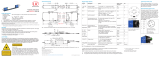
4.5 Connections for optoCONTROL ODC2520
Power supply
LAN connection COM connection
RS422 / RS232
PC190-2
SCD2520-3
PC/SC190-3
PS2020
To light source
CE2520x
PC/SC2520-3/IF2008
Ports on the display bottom side Ports on the controller for ODC 2520
Fig. 8 Connections for optoCONTROL ODC2520
The Ethernet connection requires the SCD2520-3 and PC190-2 cables, see A 1. The Ethernet version (blue
lines) requires to supply the ODC2520 sensor separately with the operating voltage.
The RS422 connection requires the PC/SC2520-3/IF2008 and PC/SC190-3 cables, see A 1.
With the RS422 variant (red lines), the ODC2520 sensor is supplied via the EDU190 digital display.

Page 19
optoCONTROL EDU190
4.6 Displays
A green LED on the right side
of the display indicates if the
transmission is active.
Flashing when the digital display is connected with the sensor.
No flashing when the digital display is not connected with the sen-
sor.
The ON/OFF status is dis-
played on the blue multicolor
LED on the left side of the
digital display.
ON
OFF

Page 20
optoCONTROL EDU190
5. Software
5.1 Basic Settings
The digital display is configured to automatically detect the connected sensor type and to adjust the user
interface accordingly. It does not matter whether the digital display is connected via the RS232/RS422 con-
nection or the Ethernet connection.
The set standard IP is 169.254.168.150.
i
For automatic detection via Ethernet, the sensor should be set to the standard IP address. You can also
change the sensor IP address in the address field.
If connection problems occur with Ethernet, please check whether the sensor has been set to the standard IP
address. If necessary, reset the sensor to factory settings.
In order to use a different IP address of the EDU190, please contact the MICRO-EPSILON Eltrotec GmbH
support, see 7.
i
When using the RS232/RS422 serial interface, the standard baud rate of the respective optoCONTROL
ODC must be used. If connection problems occur, use the baud rate of the respective factory settings.
In order to use a different setting of the serial interface, please contact the MICRO-EPSILON Eltrotec GmbH
support, see 7.
Some changes that are selected via the web interface of the ODC 2520 sensor or the ODC 12XX software will
not take effect until the digital display is restarted.
Disconnect the display from the power supply.
Restart the digital display when you need to change the controller settings.
i
Refer to the respective operating instructions for the sensor settings.
The software can be set in German or English and has several buttons for the visualization, configuration and
retrieval of sensor data.
/