
5000 and 5100 Series
Digital Analog Clocks
Installation and Operation Manual
Edition D
5000/5100 MAN


Edition D
August 2006
5000/5100Series
Digital Analog Clocks
Installation and Operation Manual

Trademarks and Copyrights
CCS, CCS CoPilot, CCS Navigator, CCS Pilot, Command Control System,
CineTone, CinePhase, CineSound, DigiBus, DigiPeek, Digital Glue,
DigiWorks, DTV Glue, EventWORKS, EZ HD, Genesis, HDTV Glue,
Image Q, Icon, IconLogo, IconMaster, IconMaster Nav, IconSet, Icon
Station, Inca, Inca Station, InfoCaster, Inscriber, Inscriber CG—FX,
Integrator, LeFont, Leitch, LogoMotion, MediaFile, MIX BOX, NEO, the
NEO design, NEOSCOPE, NewsFlash, Nexio, Opus, Panacea,
PanelMAPPER, Platinum, Portal, PROM-Slide, RouterMAPPER,
RouterWORKS, Signal Quality Manager, SpyderWeb, SuiteView,
TitleMotion, UNIFRAME, Velocity, VelocityHD, VideoCarte, Videotek,
and X75 are trademarks of the Harris Corporation, which may be registered
in the United States, Canada, and/or other countries. All other trademarks
are the property of their respective owners.
Copyright 2006, Harris Corporation. All rights reserved. This publication
supersedes all previous releases. Printed in Canada.
Warranty Information
The Limited Warranty Policy provides a complete description of your
warranty coverage, limitations, and exclusions, as well as procedures
for obtaining warranty service. To view the complete warranty, visit
www.broadcast.harris.com/leitch
.

5000/5100 Series Digital Analog Clocks Installation and Operation Manual i
Contents
Preface
Manual Information ............................................................................... iii
Purpose ............................................................................................ iii
Audience ......................................................................................... iii
Revision History ............................................................................. iii
Writing Conventions ....................................................................... iv
Obtaining Documents ..................................................................... iv
Unpacking/Shipping Information ............................................................v
Unpacking a Product .........................................................................v
Product Servicing ..............................................................................v
Returning a Product ..........................................................................v
Restriction on Hazardous Substances (RoHS) Compliance .................. vi
Waste from Electrical and Electronic Equipment (WEEE) Compliance vii
Safety ................................................................................................... viii
Safety Terms and Symbols in this Manual ................................... viii
Chapter 1: DAC-5000 Series Digital Analog Clocks
Overview ..................................................................................................1
Introduction ..............................................................................................2
Installation ................................................................................................3
Wall Mounting ..................................................................................3
Rack Mounting .................................................................................5
Rear Panel .........................................................................................6
Control Modes ..........................................................................................8
Calibration of the Internal Time Base ...............................................8
General Operation ....................................................................................9
Clock Control Modes ........................................................................9
Clock Setting Controls ....................................................................10

ii 5000/5100 Series Digital Analog Clocks Installation and Operation Manual
Contents
Specifications ........................................................................................ 12
Electrical ........................................................................................ 12
Primary Drive Inputs ...................................................................... 12
Secondary Time Bases ................................................................... 12
Mechanical ..................................................................................... 13
Chapter 2: ADC-5100 Series Analog Digital Clocks
Overview ............................................................................................... 15
Introduction ........................................................................................... 16
Installation ............................................................................................. 18
Wall Mounting ............................................................................... 18
Rack Mounting ............................................................................... 20
Desk Mounting ............................................................................... 20
Rear Panel ...................................................................................... 21
Control Modes ....................................................................................... 23
General Operation ................................................................................. 24
Clock Control Modes ..................................................................... 24
Clock Setting .................................................................................. 26
Troubleshooting .................................................................................... 32
Hands are Offset ............................................................................. 32
Specifications ........................................................................................ 34
Electrical ........................................................................................ 34
Inputs and Outputs ......................................................................... 34
Time Base ...................................................................................... 34
Controls .......................................................................................... 35
Mechanical ..................................................................................... 35

5000/5100 Series Digital Analog Clocks Installation and Operation Manual iii
Preface
Manual Information
Purpose
This manual details the features, installation, operation, maintenance,
and specifications for 5000/5100 Series Digital Analog Clocks.
Audience
This manual is written for engineers, technicians, and operators
responsible for installation, setup, maintenance, and/or operation of
5000/5100 Series Digital Analog Clocks.
Revision History
Table P-1. Revision History of Manual
Edition Date Comments
C December 1998 Full release
D August 2006 Manual reformatted and updated

iv 5000/5100 Series Digital Analog Clocks Installation and Operation Manual
Preface
Writing Conventions
To enhance your understanding, the authors of this manual have
adhered to the following text conventions:
Obtaining Documents
Product support documents can be viewed or downloaded from our
Web site at www.broadcast.harris.com/leitch
(go to Support>
Documentation). Alternatively, contact your customer service
representative to request a document.
Table P-2. Writing Conventions
Term or
Convention
Description
Bold Indicates dialog boxes, property sheets, fields, buttons,
check boxes, list boxes, combo boxes, menus,
submenus, windows, lists, and selection names
Italics Indicates E-mail addresses, the names of books or
publications, and the first instances of new terms and
specialized words that need emphasis
CAPS Indicates a specific key on the keyboard, such as
ENTER, TAB, CTRL, ALT, or DELETE
Code Indicates variables or command-line entries, such as a
DOS entry or something you type into a field
> Indicates the direction of navigation through a hierarchy
of menus and windows
hyperlink Indicates a jump to another location within the
electronic document or elsewhere
Internet address
Indicates a jump to a Web site or URL
Note
Indicates important information that helps to avoid and
troubleshoot problems

5000/5100 Series Digital Analog Clocks Installation and Operation Manual v
Preface
Unpacking/Shipping Information
Unpacking a Product
This product was carefully inspected, tested, and calibrated before
shipment to ensure years of stable and trouble-free service.
1. Check equipment for any visible damage that may have occurred
during transit.
2. Confirm that you have received all items listed on the packing list.
3. Contact your dealer if any item on the packing list is missing.
4. Contact the carrier if any item is damaged.
5. Remove all packaging material from the product and its associated
components before you install the unit.
Keep at least one set of original packaging, in the event that you need to
return a product for servicing.
Product Servicing
5000/5100 Series Digital Analog Clocks are not designed for field
servicing. All upgrades, modifications, or repairs require you to return
the product to the Customer Service center.
Returning a Product
In the unlikely event that your product fails to operate properly, please
contact Customer Service to obtain a Return Authorization (RA)
number, then send the unit back for servicing.
Keep at least one set of original packaging in the event that a product
needs to be returned for service. If the original package is not available,
you can supply your own packaging as long as it meets the following
criteria:
• The packaging must be able to withstand the product’s weight.
• The product must be held rigid within the packaging.
• There must be at least 2 in. (5 cm) of space between the product and
the container.
• The corners of the product must be protected.
Ship products back to us for servicing prepaid and, if possible, in the
original packaging material. If the product is still within the warranty
period, we will return the product prepaid after servicing.

vi 5000/5100 Series Digital Analog Clocks Installation and Operation Manual
Preface
Restriction on Hazardous Substances (RoHS)
Compliance
Directive 2002/95/EC—commonly known as the European Union (EU)
Restriction on Hazardous Substances (RoHS)—sets limits on the use of
certain substances found in electrical and electronic equipment. The
intent of this legislation is to reduce the amount of hazardous chemicals
that may leach out of landfill sites or otherwise contaminate the
environment during end-of-life recycling. The Directive takes effect on
July 1, 2006, and it refers to the following hazardous substances:
• Lead (Pb)
• Mercury (Hg)
• Cadmium (Cd)
• Hexavalent Chromium (Cr-V1)
• Polybrominated Biphenyls (PBB)
• Polybrominated Diphenyl Ethers (PBDE)
According to this EU Directive, all products sold in the European Union
will be fully RoHS-compliant and “lead-free.” (See our Web site,
www.broadcast.harris.com/leitch
, for more information on dates and
deadlines for compliance.) Spare parts supplied for the repair and
upgrade of equipment sold before July 1, 2006 are exempt from the
legislation. Equipment that complies with the EU directive will be
marked with a RoHS-compliant emblem, as shown in Figure P-1.
Figure P-1. RoHS Compliance Emblem

5000/5100 Series Digital Analog Clocks Installation and Operation Manual vii
Preface
Waste from Electrical and Electronic
Equipment (WEEE) Compliance
The European Union (EU) Directive 2002/96/EC on Waste from
Electrical and Electronic Equipment (WEEE) deals with the collection,
treatment, recovery, and recycling of electrical and electronic waste
products. The objective of the WEEE Directive is to assign the
responsibility for the disposal of associated hazardous waste to either
the producers or users of these products. Effective August 13, 2005,
producers or users will be required to recycle electrical and electronic
equipment at end of its useful life, and may not dispose of the
equipment in landfills or by using other unapproved methods. (Some
EU member states may have different deadlines.)
In accordance with this EU Directive, companies selling electric or
electronic devices in the EU will affix labels indicating that such
products must be properly recycled. (See our Web site,
www.broadcast.harris.com/leitch
, for more information on dates and
deadlines for compliance.) Contact your local sales representative for
information on returning these products for recycling. Equipment that
complies with the EU directive will be marked with a WEEE-compliant
emblem, as shown in Figure P-2.
Figure P-2. WEEE Compliance Emblem

viii 5000/5100 Series Digital Analog Clocks Installation and Operation Manual
Preface
Safety
Carefully review all safety precautions to avoid injury and prevent
damage to this product or any products connected to it. If this product is
rack-mountable, it should be mounted in an appropriate rack using the
rack-mounting positions and rear support guides provided. It is
recommended that each frame be connected to a separate electrical
circuit for protection against circuit overloading. If this product relies
on forced air cooling, it is recommended that all obstructions to the air
flow be removed prior to mounting the frame in the rack.
If this product has a provision for external earth grounding, it is
recommended that the frame be grounded to earth via the protective
earth ground on the rear panel.
IMPORTANT! Only qualified personnel should perform service
procedures.
Safety Terms and Symbols in this Manual
WARNING
Statements identifying conditions or
practices that may result in personal injury
or loss of life. High voltage is present.
CAUTION
Statements identifying conditions or
practices that can result in damage to the
equipment or other property.

5000/5100 Series Digital Analog Clocks Installation and Operation Manual 1
Chapter 1
DAC-5000 Series Digital Analog Clocks
Overview
This chapter provides installation and operation information about the
DAC-5000 Series digital analog clocks. It includes the following topics:
• “Introduction” on page 2
• “Installation” on page 3
• “Control Modes” on page 8
• “General Operation” on page 9
• “Specifications” on page 12

2 5000/5100 Series Digital Analog Clocks Installation and Operation Manual
Chapter 1: DAC-5000 Series Digital Analog Clocks
Introduction
The DAC-5000 Series Digital Analog Clocks feature a quiet, digitally
controlled drive mechanism. Each hand is driven independently by a
separate motor and drive train. The exact position of each hand is
microprocessor controlled and virtually error free.
The standard clock face provides two sets of numerals: 1 to12 are black,
and 13 to 24 are red. A clock face with only black numerals from 1 to
12 is optional.
The DAC-5000 Series clocks operate with standard drive signals and
consequently can be easily integrated into new or existing systems.
Selection of the drive signals is made by switches located on the back
panel. The usable drive signals are:
• Serial Timecode (SMPTE or EBU)
• 12 VDC Impulse Clock
• Internal Time Base
• Line Frequency Reference
All clock models accept Serial Timecode are in either the SMPTE or
EBU format.
If reception of the timecode is lost, the error LED located on the clock’s
face will light up and the clock will automatically switch to either the
Internal Time Base or the Line Frequency Reference, as selected on the
back panel switches, without interruption of its operation.
The Internal Time Base is provided by a 4.9 MHz crystal oscillator. The
Line Frequency Reference uses a 50/60 Hz power line. Selection of
either 50 or 60 Hz is made by soldering a jumper on the 5000DL Drive
Logic module.
The following models are available:
• DAC-5016 16 inch illuminated, wall mounting. Rack mounting
kit optional.
• DAC-5012 12 inch illuminated, wall mounting. Rack mounting
kit optional.
• DAC-5008 8 inch illuminated, wall mounting. Rack mounting kit
optional.
• DAC-5006 5 inch non-illuminated, rack mounting.
• DAC-5005 5 inch non-illuminated, desk top.

5000/5100 Series Digital Analog Clocks Installation and Operation Manual 3
Chapter 1: DAC-5000 Series Digital Analog Clocks
Installation
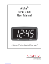
Wall Mounting
Figure 1-1. Typical Wall Mount
The DAC-5008, DAC-5012 and DAC-5016 Digital Analog Clocks are
designed for wall mounting. Rack mounting kits are optional.
The rear panels of both the DAC-5012 and DAC-5016 clocks are
provided with four rubber feet and four keyholes while the DAC-5008
has only three keyholes. These are dimensioned for #8 screws. The rear
panel also has a large depression to contain the connecting wires and
allow the clock to be placed close to the wall.

4 5000/5100 Series Digital Analog Clocks Installation and Operation Manual
Chapter 1: DAC-5000 Series Digital Analog Clocks
Table 1-1 provides information about clock wall mounting
specifications
Note
A convenient template drawing showing the correct mounting centers
is included with the clock.
Clearances
Table 1-2 lists the minimum clearances, measured in inches, from the
mounting keyhole centers to the outside edge of each clock:
Table 1-1. Clock Wall Mounting Specifications
Clock
Overall
Dimensions
Mounting Keyhole
Centers
DAC-5016 17.45×17.45 in. 16.0×15.5 in.
(4 keyholes)
DAC-5012 13.95×13.95 in. 12.0×10.5 in.
(4 keyholes)
DAC-5008 10.45×10.45 in. 8.0×8.0 in.
(3 keyholes). The bottom
single keyhole is located
Table 1-2. Clock Clearances
Clock Clearances (Inches)
DAC-5016
• Top edge 0.8
• Sides 0.725
• Bottom edge 1.275
DAC-5012
• Top edge 1.12
• Sides 0.975
• Bottom edge 2.35
DAC-5008
• Top edge 0.825
• Sides 1.275
• Bottom edge 1.85

5000/5100 Series Digital Analog Clocks Installation and Operation Manual 5
Chapter 1: DAC-5000 Series Digital Analog Clocks
Rack Mounting
The DAC-5008, DAC-5012 and DAC-5016 clocks can be rack
mounted with the optional rack mounting kit. The kit is installed by
removing the back panel side screws, placing the rack mount in
position, and reinstalling the screws. The rack mount kits are designated
as 5008RM, 5012RM, and 5016RM, respectively.
The DAC-5006 clock is pre-designed to be rack mounted, and does not
require the optional rack mounting kit. It has an overall dimension of
7×19 inches.
Table 1-3 lists the required rack space for each clock.
Table 1-3. Required Space For Rack Mounting
Clocks Rack Units Inches
DAC-5016 10 17.45
DAC-5012 8 13.95
DAC-5008 6 10.45
DAC-5006 4 7

6 5000/5100 Series Digital Analog Clocks Installation and Operation Manual
Chapter 1: DAC-5000 Series Digital Analog Clocks
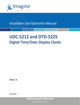
Rear Panel
Figure 1-2. DAC-5008/5012/5016 Rear Panel
The rear panels of the DAC-5008/5012/5016 have two spring-loaded
speaker-type connectors (one red, one black) to accept the Primary
Reference input (i.e. SMPTE Serial Timecode or Impulse Drive
signals).
A standard AC connector for the power feed of the unit can be found in
the recessed area running across the middle of the rear panel.
Spring Loaded
“Speaker-Type”
Connectors (red
and black)
Push-Buttons:
CW, CCW,
MANUAL SET
DIP Switches
Clock Modes
(factory set)
AC
Connector
(plug)
115/230 VAC 10%250/60Hz
25VA Max
+
OPERATION MODE
DAC-5012
DAC-5016
230 VAC
115 VAC
LINE VOLTAGE
DAC-5008
50 HZ
60 HZ
LINE FREQUENCY
12 4356
OPEN
Time Code
SMPTE
Internal
Nor mal
Nor mal
Step Seconds
Impulse
EBU
Line
Use Offset
Run On Secondary
Sweep Seconds
CW
CCW
MANUAL
SET
Multifunctional Pushbuttons
Full Instructions in Manual

5000/5100 Series Digital Analog Clocks Installation and Operation Manual 7
Chapter 1: DAC-5000 Series Digital Analog Clocks
Below this recessed area are the multifunction clock setting buttons and
the six DIP switches (SW1 to SW6), all of which must be set prior to
installation.
Figure 1-3. DAC-5005 (left) and DAC-5006 (right) Rear Panels
MANUAL
SET
CCW
CW
115/2 30 VAC 0 %
50/60Hz
25VA Max
+2
12 4356
OPEN
Run on Secondary
Use Offset
Secondary Ref-Line
Time Code Format-EBU
Not Used
Normal
Normal
Internal
SMPTE
Primary Ref-Time Code
230 VAC
115 VAC
LI N E VO LTAGE
50 HZ
60 HZ
LINE FREQUENCY
MANUAL
SET
CCW
CW
115/230 VAC 0%
50/60Hz
25VA Max
+2
12 4356
OPEN
Run on Secondary
Use Offset
Secondary Ref-Line
Time Code Format-EBU
Not Used
Normal
Normal
Internal
SMPTE
Primary Ref-Time Code
230 VAC
115 VAC
LINE VOLTAGE
50 HZ
60 HZ
LINE FREQUENCY

8 5000/5100 Series Digital Analog Clocks Installation and Operation Manual
Chapter 1: DAC-5000 Series Digital Analog Clocks
Control Modes
Table 1-4 lists the Clock Control mode DIP switch options.
Calibration of the Internal Time Base
This procedure is used to adjust the frequency of the 4.9152 crystal
oscillator. The accuracy of this adjustment directly affects the accuracy
of the Internal Time Base. The only equipment required is a high
resolution frequency counter.
Connect the frequency counter to the clock test point provided at pin 9
of the CMOS NSC800N Microprocessor IC11. Adjust the 6-25 pF
trimmer capacitor connected to pin 11 of IC11 until the counter
indicates 2.457.600 Hz. It is recommended to use the longest sampling
time possible.
Table 1-4. Clock Control Mode DIP switch options
Dip Switch
Switch Options
Open Closed
SW1 Timecode Impulse
SW2 SMPTE EBU
SW3 Internal Line
SW4 Normal Use offset
SW5 Normal Run on secondary
SW6 (Secondary) NA NA
Page is loading ...
Page is loading ...
Page is loading ...
Page is loading ...
Page is loading ...
Page is loading ...
Page is loading ...
Page is loading ...
Page is loading ...
Page is loading ...
Page is loading ...
Page is loading ...
Page is loading ...
Page is loading ...
Page is loading ...
Page is loading ...
Page is loading ...
Page is loading ...
Page is loading ...
Page is loading ...
Page is loading ...
Page is loading ...
Page is loading ...
Page is loading ...
Page is loading ...
Page is loading ...
Page is loading ...
Page is loading ...
Page is loading ...
Page is loading ...
-
 1
1
-
 2
2
-
 3
3
-
 4
4
-
 5
5
-
 6
6
-
 7
7
-
 8
8
-
 9
9
-
 10
10
-
 11
11
-
 12
12
-
 13
13
-
 14
14
-
 15
15
-
 16
16
-
 17
17
-
 18
18
-
 19
19
-
 20
20
-
 21
21
-
 22
22
-
 23
23
-
 24
24
-
 25
25
-
 26
26
-
 27
27
-
 28
28
-
 29
29
-
 30
30
-
 31
31
-
 32
32
-
 33
33
-
 34
34
-
 35
35
-
 36
36
-
 37
37
-
 38
38
-
 39
39
-
 40
40
-
 41
41
-
 42
42
-
 43
43
-
 44
44
-
 45
45
-
 46
46
-
 47
47
-
 48
48
-
 49
49
-
 50
50


Harris ADC-5105 Operating instructions
- Category
- Wall clocks
- Type
- Operating instructions
Ask a question and I''ll find the answer in the document
Finding information in a document is now easier with AI
Related papers
-
Harris ADC 100 User manual
-
-
-
-
-
-
-
-
Harris OTM-20 Installation And Operation Handbook
-
Other documents
-
Acroprint Wall Mounting Template Owner's manual
-
 MFJ 117 User manual
-
 Imagine NEO DVR-3901 Operating instructions
-
 Adaptive ALPHA User manual
-
Tektronix WFM601 User manual
-
-
-
 Imagine UDC-5212 Operating instructions
-
 ProX MH-5106 User manual
-
American Time Wi-Fi Battery Analog Clock Quick Start Installation Manual


