Deckorators 408512 Installation guide

Category
Car kits
Type
Installation guide
Tools and Items Needed
Contemporary Composite Line Railing - 6' On-Center:
One line rail kit (fig. 1), which contains:
1 - Top rail
1 - Bottom rail
1 - Rail support with connector
1 - Contemporary line rail bracket kit, which contains:
4 - Brackets
4 - Bracket covers
Screws
14 - 32-3/4" Round Aluminum Balusters
1 - 40" Post sleeve plus one to end a railing section for 36" rail height
(sold separately)
1 - Post cap for each post sleeve (sold separately)
1 - Post base trim for each post sleeve (included with post sleeve)
Post sleeve, post cap and trim are not included in rail kit.
One stair rail kit (fig. 1), which contains:
1 - Top rail
1 - Bottom rail
1 - Rail support with connector
1 - Contemporary stair rail bracket kit, which contains:
4 - Brackets
4 - Bracket covers
Screws
12 - 32-3/4" Round Aluminum Balusters
1 - 48" Post sleeve plus one to end a railing section for 36" rail height
(lower) (sold separately)
1 - Post cap for each post sleeve (sold separately)
1 - Post base trim for each post sleeve (included with post sleeve)
Post sleeve, post cap and trim are not included in rail kit.
Contemporary Composite Stair Railing - 6' On-Center:
Prior to construction, check with your local regulatory agency for special code requirements in your area. Structural support should come from
either the continuation of deck support posts that extend up through the deck floor, railing posts that are bolted to the inside of the rim/outer joists or structural
post mounts. The post spacing will be less for angled rail applications. Always measure prior to securing the posts when installing angled rail sections. Install
railing posts before deck boards are fastened to the joists.
The railing comes pre-routed for balusters. Pre-drilling all other screw holes is essential for successful rail installation. Do not over-tighten screws. Read
instructions completely to get an understanding of how the product goes together and how each piece affects the others.
Step 1 Determine the number of railing posts needed for your deck. Post spacing is 6' on-center. Example: A 12' x 16' deck attached to a building with a 4'
access opening on one side will require a total of eight posts (fig. 3).
Line Railing Installation Instructions
GRAB AND GO CONTEMPORARY COMPOSITE
RAILING INSTALLATION INSTRUCTIONS
fig. 3
fig. 2
Contemporary Composite Railing
Bottom
Top
Top Rail
6ft on-center
Top Rail Bracket
and Bracket Cover
Baluster
Bottom
Rail
Rail
Support
Bottom Rail Bracket
and Bracket Cover
Post
Base
Trim
40-in
Post
Post Cap
fig. 1
(1) Top Rail (1) Rail Support (2) Top Rail Brackets (2) Bottom Rail Brackets (16) Large Screws
• Drill/power screwdriver
• Carriage bolts
• Hammer
• Miter or circular saw with
carbide tip blade
• Clear exterior construction
adhesive
• Marked speed square
• Tape measure
• Carpenter’s level
• Carpenter’s pencil
• Adjustable wrench or socket
wrench for bolts, etc.
• Safety glasses/goggles
• #1 and #2 square head drill bits
1/8" drill bit
Rubber mallet
(1) Bottom Rail (12) Small Screws(14 or 12) Balusters (1) Rail Support Connector
Step 2 Install railing posts prior to installing deck boards. Cedar or pressure-treated pine
4x4 railing posts or a post mount provides the structural strength for the railing. The length of
each post is determined by the total of the joist width (typically 7-1/4") + decking thickness (1")
+ railing height (36") + spacing for post cap (1-1/4") = 45-1/2". Important: Do not notch the
4x4 railing posts. Notching will reduce the strength of the post and could result in
railing collapse or failure (fig. 4).
Step 3 Position, plumb with a level, and clamp the railing post on the interior face of the joist.
Plumb again. The 4x4 railing post should be bolted to the inside of the joist using two 1/2" x 6"
galvanized carriage bolts. Corner posts use a third carriage bolt inserted through the adjacent
joist (fig. 7).
Step 4 Install decking; notch deck boards to fit around the 4x4 railing posts. Allow 1/4"
space between the deck boards and any permanent structure or post. Additional blocking
may be necessary on the 4x4 for fastening deck boards.
Step 5 Trim 4x4 post sleeves to length. Post sleeves should be a minimum of 1-1/2" longer
than the railing height. Example: For a 36" high railing, trim post sleeve to a minimum of 38-
1/2", can be left longer if desired. Slide a trimmed post sleeve over each 4x4 railing post. Post
sleeve should slide easily over the post. DO NOT FORCE post sleeve onto post. Twisted or
crooked 4x4s should be replaced. Slide a post base trim (optional) over each post sleeve for
a finished look. Note: It is recommended to install the post base trim prior to installing the
bottom rail. However, the two-piece design does allow the installer to add the post base
trim after the rail has been installed. To install, apply a thin line of clear exterior construction
adhesive to the inside of the post trim, where it will contact the post sleeve, and snap into
place around the base of the post sleeve.
Step 6 Measure the distance between installed post sleeves to determine the length of the
top and bottom rails. Place the bottom rail in position next to the posts and adjust so the
distance between the first baluster hole and post is greater than 2" and equal on both ends
(refer to fig. 5). Mark the rail. Cut the bottom rail. Cut the top rail to the same spacing and
length.
Step 7 Find the center of the underside of the bottom rail and attach the baluster connector
included with the rail support using the screw provided. Check building code requirements for
the maximum spacing between deck surface and bottom of rail (sweep); we recommend 3"
but it can be less if desired. If necessary, trim the rail support to the determined height
(fig. 6). Drill two ¼" drain holes through the bottom of the rail to prevent trapping
water. Center drain holes between two baluster locations as baluster can block the
pathway and stop water from properly draining.
Step 8 Place the line rail bracket covers and line brackets on the ends of the bottom rail.
Install the rail support and prop the bottom rail between the posts using blocks cut to size.
Check the rail for level. Using the line bracket as a guide, mark the screw positions on the
post sleeve and rail on both ends. Pre-drill 1/8" pilot holes through the post sleeve and rail.
Attach the line bracket to the post sleeve using four #8-15 x 2" - #2 square drive pan head
screws and then attach line bracket to rail using two #10-16 x ¾" - #2 square drive pan head
self-drilling screws (fig. 5).
Step 9 Place a baluster into each routed hole in the bottom rail. Make sure baluster is fully
seated in rail.
Step 10 Place the line rail bracket covers and line brackets on the ends of the top rail.
Position the top rail by placing the balusters inside the routed holes, while working from one
end to the other. Check the rail for level. Using the line bracket as a guide, mark the screw
positions on the post sleeve and rail on both ends. Pre-drill 1/8" pilot holes through the post
sleeve and rail. Attach the line bracket to the post sleeve using four #8-15 x 2" - #2 square
drive pan head screws and then attach line bracket to rail using four #10-16 x ¾" - #2 square
drive pan head self-drilling screws. Important: For the top rail only, pre-drill and attach
two additional screws through the top of the bracket, into the top rail (fig. 8).
Step 11 Slide the rail bracket cover over the rail bracket and snap into place.
Step 12 Apply a thin line of clear exterior construction adhesive to the inside rim of a post cap
and place firmly on the post. Repeat for each post.
fig. 4
LevelRailInst.pdf
3" Sweep
Rail
Support
Bottom Rail
Bracket and
Bracket Cover
Equal spacing on both ends
Baluster
Temporary supports
Bottom Rail
fig. 5
Routed Holes
For Baluster
Bottom Rail
Rail Support
Connector
Rail Support
Drill 1/4" Drain Holes
Through Bottom
fig. 6
fig. 7
PostDetail.pdf
Galvanized
Carriage Bolts
into 4x4 Post
fig. 8
Assembled
IMPORTANT:
SEE STEP 10
For top rail add
two screws here
Note: Stair angle must be between 30 and 35 degrees for brackets in kit to fit properly.
Step 1 Determine the number of stair railing posts needed for your deck. Post spacing is 6'
on-center.
Step 2 Install stair railing posts prior to installing stair treads. Cedar or pressure-treated
pine 4x4 railing posts or a post mount provides the structural strength for the stair railing.
The length of each post is determined by the total of the stringer width + tread thickness
+ stair railing height + spacing for post cap. Important: Do not notch the 4x4 railing
posts. Notching will reduce the strength of the post and could result in railing
collapse or failure (fig. 4).
Step 3 Position, plumb with a level, and clamp the stair railing post on the interior face of the
stringer. Plumb again. The 4x4 stair railing post should be bolted to the inside of the stringer
using two 1/2"x6" galvanized carriage bolts. Corner posts use a third carriage bolt inserted
through the adjacent joist (fig. 7). Ground level posts should be set in concrete.
Step 4 Install treads; notch treads to fit around the 4x4 stair railing posts. Allow 1/4" space
between the treads and any permanent structure or post. Additional blocking may be necessary
on the 4x4 for fastening treads.
Step 5 Trim 4x4 post sleeves to length. Post sleeves should be a minimum of 1-1/2"
longer than the railing height. Stair posts may be longer to allow for the riser height. Slide
a trimmed post sleeve over each 4x4 railing post. Post sleeve should slide easily over
the post. DO NOT FORCE post sleeve onto post. Twisted or crooked 4x4s should be
replaced. Slide a post base trim over each post sleeve for a finished look. Note: It is
recommended to install the post base trim prior to installing the bottom rail. However, the
two-piece design does allow the installer to add the post base trim after the rail has been
installed. To install, apply a thin line of clear exterior construction adhesive to the inside of
the post trim, where it will contact the post sleeve, and snap into place around the base of
the post sleeve.
Step 6 Measure the distance between installed post sleeves to determine the length of the
top and bottom rails. Place the bottom rail on the stair treads next to the posts and adjust
so the distance between the first baluster hole and post is greater than 2-3/4" minimum and
equal on both ends (fig. 9). Mark the rail to the proper length and angle. Cut the bottom rail.
Cut the top rail to the same length and angle (fig. 10). Drill one ¼" drain hole through the
bottom of the rail to prevent trapping water. Position the hole toward the lower end
of the rail, roughly 2" from rail end to avoid the lower bracket.
Step 7 Place the proper rail bracket covers and stair brackets on the ends of the bottom rail.
Pay particular attention to the brackets being used as they differ based on top/bottom rail
and up/down angle. Determine the postion of the rail support and attach to the bottom rail.
Prop the bottom rail between the posts on the stair treads (fig. 10). You may need to place
equal shims between two stair tread noses to elevate the bottom rail. Check for requirements
in your area. Typically, a 6" sphere may not be allowed to pass through the triangle formed
by the bottom rail, tread and riser (fig. 9). Center the stair bracket on the post. Using the
stair bracket as a guide, mark the screw positions on the post sleeve and rail on both ends.
Pre-drill 1/8" pilot holes through the post sleeve and rail. Attach the stair bracket to the post
sleeve using four #8-15 x 2" - #2 square drive flat head screws and then attach stair bracket
to rail using two #8-16 x ¾" - #1 square drive wafer head self-drilling screws.
Step 8 Place a baluster into each routed hole in the bottom rail. Make sure baluster is fully
seated in rail (fig 11).
Step 9 Place the stair rail bracket covers and stair brackets on the ends of the top rail. Position
the top rail by placing the balusters inside the routed holes, while working from one end to the
other. Center the stair bracket on the post. Using the stair bracket as a guide, mark the screw
positions on the post sleeve and rail on both ends. Pre-drill 1/8" pilot holes through the post
sleeve and rail. Attach the stair bracket to the post sleeve using four #8-15 x 2" - #2 square
drive flat head screws and then attach stair bracket to rail using four #8-16 x ¾" - #1 square
drive wafer head self-drilling screws. Important: For the top rail only, pre-drill and attach
two additional screws through the top of the bracket, into the top rail (fig. 8).
Step 10 Slide the rail bracket cover over the rail bracket and snap into place.
Step 11 Apply a thin line of clear exterior construction adhesive to the inside rim of a post
cap and place firmly on the post. Repeat for each post.
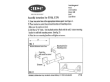
Stair Railing Installation Instructions
Top Rail Bracket
and Bracket Cover
Rail Support
Bottom Rail
6" Max
StairAsm.pdf
Top Rail
Equal spacing on
both ends
Post
Cap
Post
Base
Trim
40-in
Post
Sleeve
Baluster
Bottom Rail Bracket
and Bracket Cover
48-in
Post
Sleeve
Drill 1/4" Drain Hole
Through Bottom
Post
Sleeve
Post
Cap
Post
Base
Trim
Post
Sleeve
Bottom
Rail
StairRail.pdf
Distance
Between
Posts
Mark Rail
for Length
and Angle
Mark Rail for
Length and Angle
Drill 1/4" Drain Hole Through Bottom
fig. 9
g. 10
Baluster
Bottom Rail
BottomStairRail.pdf
g. 11
THE DIAGRAMS AND INSTRUCTIONS IN THIS BROCHURE ARE FOR ILLUSTRATION PURPOSES ONLY AND ARE NOT MEANT TO REPLACE A LICENSED PROFESSIONAL. ANY CONSTRUCTION OR USE OF THE PRODUCT MUST BE IN ACCORDANCE
WITH ALL LOCAL ZONING AND/OR BUILDING CODES. THE CONSUMER ASSUMES ALL RISKS AND LIABILITY ASSOCIATED WITH THE CONSTRUCTION OR USE OF THIS PRODUCT. THE CONSUMER OR CONTRACTOR SHOULD TAKE ALL NECES-
SARY STEPS TO ENSURE THE SAFETY OF EVERYONE INVOLVED IN THE PROJECT, INCLUDING, BUT NOT LIMITED TO, WEARING THE APPROPRIATE SAFETY EQUIPMENT. EXCEPT AS CONTAINED IN THE WRITTEN LIMITED WARRANTY, THE
WARRANTOR DOES NOT PROVIDE ANY OTHER WARRANTY, EITHER EXPRESS OR IMPLIED, AND SHALL NOT BE LIABLE FOR ANY DAMAGES, INCLUDING CONSEQUENTIAL DAMAGES.
©2020 UFP Retail Solutions, LLC. Deckorators is a registered trademark of UFP Industries, Inc. in the U.S. All rights reserved.
1801 E. Lessard St. Prairie du Chein, WI 53821
10904 10/20
www.lowes.com
  • Page 1 1
  • Page 2 2
  • Page 3 3

Deckorators 408512 Installation guide

Category
Car kits
Type
Installation guide

Ask a question and I''ll find the answer in the document

Finding information in a document is now easier with AI