Page is loading ...

Prior to construction, check with your local regulatory agency for special code
requirements in your area. Common railing height is 36" or 42". Structural support
should come from either the continuation of deck support posts that extend up
through the deck floor or railing posts that are bolted to the inside of the rim or outer
joists. Never span more than 8' on-center between railing posts. Install railing posts
before deck boards are fastened to the joists. Pre-drilling of all railing components is
essential to successful installation. Work area should be kept clean of debris, including
metal shavings that can cause scratching. Do not over-tighten screws. Read instructions
completely to get an understanding of how the product goes together and how each piece
affects the other.
Step 1 Determine the number of railing posts needed for your deck. Post spacing is 8'
on-center. Example: A 16x20 deck attached to a building with a 4' access opening on
one side will require a total of eight posts (Figure 2).
Step 2 Install rail posts prior to installing deck boards. Cedar or pressure-treated pine
4x4 railing posts provide the structural strength for the railing. The length of each
structural post is determined by the total of the joist width (7-1/4") + decking thickness
(1") + railing height (36" or 42")=44-1/4" or 50 -1/4".
Important: Do not notch the 4x4 railing posts (Figure 3a). Notching will reduce the
strength of the post and could result in railing collapse or failure.
Step 3 Position, plumb with a level, and clamp the rail post on the interior face of the
joist. Plumb again. The 4x4 railing post should be bolted to the inside of the joists
using two 1/2"x6" galvanized carriage bolts. Corner posts use a third carriage bolt
inserted through the adjacent joist (Figure 3b).
One 8' Railing kit that contains:
• 2 rails
• 1 in-line hardware kit that contains:
4 in-line brackets
8 – #6 x 2" long #2 square head
screws
12 – #4 x 1" long #2 square head
screws
• 1 support block kit that contains:
1 support block
2 connectors
2 screws
• 20 – #8 x 1” self-drilling metal screws,
stainless steel, flat head, square drive
One cap rail kit (optional) that contains:
• 1 cap rail
• 1 insert rail
• 9 – #4 x 1" long #2 square head screws
22.5˚ and 45˚ adaptor wedges are available
for angled railing applications.
Baluster Options
Classic, Estate, Twist or Ellipse baluster kits
that each contain:
• 10 aluminum balusters
• 20 balusters needed per 8' on-center
railing section (Classic, Estate and Twist)
• 24 balusters needed per 8' on-center
railing section (Ellipse)
Baluster connector or designer baluster
connector kits that each contain:
• 20 baluster connectors
• 1 kit needed per 10 balusters
Traditional baluster kit that contains:
• 10 aluminum balusters
• 40 color-matched, stainless steel
screws
• 20 balusters needed per 8' on-center
railing section
Baroque or Arc baluster kits that each
contain:
• 5 aluminum balusters
• 20 color-matched, stainless steel
screws
• 20 balusters needed per 8' on-center
railing section
Glass
• 5 glass balusters
• 20 stainless steel screws
• 12 balusters required per 8'
on-center railing section
One post sleeve
One post cap for each post sleeve
(sold separately)
One post base trim for each
post sleeve (sold separately)
Stair rail bracket kits for stair
railing sections. Two kits required
per 8' on-center railing section.
Each kit contains:
• 2 stair brackets
• 4 – #6 x 2" long
#2 square head screws
• 8 – #4 x 1" long
#2 square head screws
Stair baluster connectors kits that each
contain (Classic, Estate, Twist and Ellipse
only):
• 20 stair baluster connectors
• 1 kit needed per 10 balusters
Cap Rail
Insert Rail
Support
Block
In-Line
Bracket (4)
Figure 1
Figure 2
Figure 3a
Fig.3.eps
Figure 3b
Scan code to get more
information about installing
Deckorators Alumimum
Railing.
Get the free mobile app at
http://gettag.mobi
8' RAILING INSTALLATION INSTRUCTIONS
Tools and items needed
• Drill/power screwdriver
• Miter or circular saw with
carbide-tipped blade
• Adjustable wrench or socket
wrench for bolts, etc.
• Assorted fasteners (see instructions)
• Tape measure
• Hammer
• Marked speed square
• Carpenter’s level
• Carpenter’s pencil
• Safety glasses/goggles
• Two clamps
• Hack saw
• Exterior-grade metal
construction adhesive
In-Line Railing Installation Instructions
For each 8' on-center railing section, you will need:

Step 4 Install decking; notch deck boards to fit around the 4x4 railing posts.
Step 5 Trim 4x4 post sleeves to length. Post sleeves should be a minimum of 1-1/2" lon-
ger than the overall railing height (Figure 4a and 4b). Allow an additional 1-1/2" in your cal-
culation if installing the optional cap rail. Example: For a 36" high railing, trim post sleeve
to a minimum of 37-1/2" (39" with cap rail). Post sleeve can be left longer if desired.
Some wood preservatives may cause an undesirable reaction when directly in contact
with aluminum. The inside of the post sleeve includes a liner to prevent direct contact
with treated structural posts. If your decking is pressure-treated, place shims under the
post sleeve or run a bead of caulk along the bottom edge of the post prior to installing
the post sleeve. This will keep the aluminum from direct contact with the treated decking
and will be concealed by the post base trim. Slide a trimmed post sleeve over each 4x4
railing post. Slide a post base trim over each post sleeve. Add a bead of caulk to the
underside of the post base trim when using treated decking.
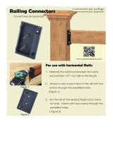
Step 6 Measure the distance between installed post sleeves to determine the length of
the top and bottom rails (Figure 1). The distance between the post and first baluster
should be less than 4" and equal on both ends (Figure 4a and 4b). Remove an
additional 1/4" on both ends (1/2" overall) for the bracket to fit between the rail and post.
Trim the top and bottom rails to length.
Angle adaptor wedges are available for 22.5˚ and 45˚ rail angles. Important: the holes
in the angle adaptor wedges line up with the stair rail connectors (sold separately). If
installing a 22.5˚ angle railing, attach the stair connectors and wedges centered on the
posts. If installing a 45˚ angle railing, attach the 45˚ adaptor wedges centered on the
posts. Attach stair connectors to the 45˚ using the provided screws.
Measure the distance between the installed angle connectors to determine the length
of the top and bottom rails. Cut the top and bottom rails to length.
Step 7 Determine the spacing of the balusters.
Classic, Estate and Twist balusters: The rails are pre-drilled with the proper spacing. At-
tach baluster connectors to the top and bottom rails. Do not over-tighten screws.
Apply silicone caulk on each connector to prevent balusters from turning or rattling after
installation is complete. The caulk should be on the outside of the round connector, and
on the inside of the designer baluster connectors. NOTE: Use screws (self tapping) that
are included with rail kit for Classic, Estate and Twist Balusters. DO NOT USE screw
included with baluster connectors.
Ellipse balusters: Both top and bottom rails will be installed with the pre-drilled holes facing
down to prevent water from collecting in the rail. 4-1/4" on-center and equal spacing for
the end spacing. Start by finding the center of the rail. Rail length ÷ 2 = center of rail.
Mark every 4-1/4" from the center line to each end. This will leave the end spacing 4"
or less on both ends and require 24 Ellipse balusters. Attach connectors to both rails
on marked locations. NOTE: Use screws (self tapping) that are included with rail kit for
Classic, Estate and Twist Balusters. DO NOT USE screw included with baluster con-
nectors.
Traditional, Baroque and Arc balusters: Both top and bottom rails will be installed with the
pre-drilled holes facing down to prevent water from collecting in the rail. Maximum 4-1/2"
on-center and equal spacing for the end spacing. Start by finding the center of the rail.
Rail length ÷ 2 = center of rail. Start the first aluminum balusters 2-1/4" on-center each
side of the center line. Mark every 4-1/2" from these lines to each end. This will leave
the end spacing less than 4" on both ends and require 20 aluminum balusters (Figure
5). Tip: Use a piece of 2x4 (3-1/2" actual) as a spacer block for the spacing between
balusters.
Glass balusters: Both top and bottom rails will be installed with the pre-drilled holes facing
down to prevent water from collecting in the rail. 7-1/2" on-center and equal spacing for the
end spacing. Start by finding the center of the rail. Rail length ÷ 2 = center of rail. Start
the first glass baluster 2-1/4" on-center of each side of the center line. Mark every 7-1/2"
from the center line to each end. This will leave the end spacing 4" or less on both ends
and require 12 glass balusters. If installing using connectors, attach connectors to both
rails on marked locations. Tip: If face-mounting to rail, use a piece of 2x4 (3-1/2" actual)
as a spacer block for the spacing between balusters (Figure 5).
Step 8 Position the bottom rail between posts and center. Check building code
Spacing of 3" is recommended, but can be more or less if codes allow (Figure 4a and 4b).
Mark the location of the bracket on both posts. Remove rail. Mark the screw locations
and pre-drill through the post sleeve only, using a 1/4" drill bit. Attach each bracket to
the post with two 2" long screws.
Step 9 A support block is needed at the center of each rail. Cut the support block to the
proper height. Attach to the bottom of the lower rail (refer to Figure 1). Find the center
of the rail and pre-drill using a 1/8" drill bit. Attach the support block connector using
the included screw. Mark the location of the support block on the deck surface and
attach the other support block connector to the deck using the included screw. Install
the bottom rail between the posts. Using the brackets as a guide, pre-drill each screw
hole using a 1/8" drill bit and attach each end to brackets using two 1" long screws. Tip:
Use a driver extension bit to avoid marring the rail or post sleeve with the drill chuck.
36-
1
/2" Rail
Height
38"
Post
Sleeve
Height
(Rail
Height
plus 1-
1
/2")
32" Baluster
Height
1-
1
/
2
"
Cap Rail
Figure 4a
37-
1
/2" Rail
Height
39"
Post
Sleeve
Height
(Rail
Height
plus 1-
1
/2")
26" Baluster
Height
1-
1
/2"
Cap Rail
Figure 4b
Figure 4c

Cap Rail
Insert Rail
To p Rail
Step 10 Figure 4a and 4b illustrate how a 36" high railing might be sized. If you want to
have your railing at a different height, use Figure 4a and 4b as planning tools to determine
the height to cut the post sleeves and support blocks. Note: Use a fixture to ensure a
consistent length (+/- 1/16").
Classic, Estate, Twist and Ellipse balusters; and Glass balusters using connectors:
Attach balusters to the lower rail by sliding onto connectors (Figure 4c).
Step 11 Position the top rail between the posts. Check for level end-to-end and vertically.
Mark the bracket location on post sleeve and remove rail. Mark the screw locations using
the bracket as a guide, and pre-drill using a 1/4" drill bit through the post sleeve only.
Attach bracket to the post with two 2" long screws at one end. Repeat for the other end.
Classic, Estate, Twist and Ellipse balusters; and Glass balusters using connectors:
Lower the top rail into position, placing the balusters onto the connectors while working
from one end of the railing to the other. Tap with a rubber mallet if needed to eliminate
any gaps. Attach the rail to each bracket by pre-drilling with a 1/8" drill bit and using
three 1" long screws. Tip: Use a driver extension bit to avoid marring the rail or post
sleeve with the drill chuck.
Traditional, Baroque, Arc balusters; and Face-Mount Glass balusters: Place the top rail in
position. Attach the rail to each bracket by pre-drilling with a 1/8" drill bit and using three
1" long screws. Tip: Use a driver extension bit to avoid marring the rail or post sleeve
with the drill chuck.
Step 12 Traditional, Baroque, Arc balusters; and Face-Mount Glass balusters: Start the first
two balusters 2-1/4" on-center each side of the center of the rail and work out to each
end. Using the baluster as a guide, drill 9/64" holes in the rails at each baluster location.
Use a 2x4 as a spacer block to space the next baluster. Working toward the ends, drill
and attach each baluster with the screws provided (Figures 5 & 6).
Step 13 (optional) Cut the cap rail and cap rail insert to length. (Note: the cap rail will be
1/2" longer than the top and bottom rails.) Center the cap rail insert on top of the top rail
and pre-drill seven 1/8" pilot holes. Attach the cap rail insert to the top rail with seven
1/2" long screws. Apply exterior-grade metal construction adhesive to the mating edges
of the insert rail. Position cap rail over the insert rail (Figure 7). Install by pressing down,
starting from one end and working to the other until the cap rail snaps into place. Gently
tap with a rubber mallet if needed.
Angled Railings: For 22.5° rail angles, cut the cap rail and cap rail insert to length and
angle using a miter saw. Sand the ends and apply touch-up paint as needed (sold sepa-
rately).Attach to the top rail following the steps above.
45° rail angles will require a cap rail wedge on top of the 45° adaptor (Figure 8). The cap
rail wedge will be cut out of the cap rail. The wedge will require a straight cut on the end
in contact with the post and a 22.5° cut on the opposite end. The distance from the post
to the wide edge of the wedge is 1-3/4”. Cut two cap rail and insert wedges using a miter
saw and install to the top of the 45° adaptors following the steps above. The cap rail will
require a 22.5° cut on both ends to match the width of the cap rail wedges. Measure the
distance between the installed wedges and cut both ends to length and angle using a mi-
ter saw. Sand the cut ends and apply touch-up paint as needed (sold separately) to make
the seam less noticeable. Attach the cap rail to the top rail following the steps above.
Step 14 Apply exterior-grade metal construction adhesive to the inside edges of the post
caps and place over each post sleeve.
Figure 5
Figure 6
Figure 7
Step 1 Cedar or pressure-treated pine 4x4 railing posts provide the structural strength
for the railing. The length of each structural post is determined by the total of the stair
stringer width (7-1/4") + decking thickness (1") + railing height (36" or 42")=44-1/4” or
50 -1/4”.
Step 2 Position, plumb with a level, and clamp the rail post on the interior face of the
stair stringer. Plumb again. The 4x4 railing post should be bolted to the inside of the stair
stringer using two 1/2" x 6" galvanized carriage bolts. Corner posts use a third carriage
bolt inserted through the adjacent joist (refer to Figure 3b). Ground level posts should be
set in concrete.
Step 3 Complete stair tread installation prior to installing post sleeves. Trim 4x4
post sleeves to length. If using post caps, post sleeves should be a minimum of
1-1/2" longer than the overall railing height (Figure 4a). Allow an additional 1-1/2" in your
calculation if installing the optional cap rail. Example: For a 36" high railing, trim post
sleeve to a minimum of 37-1/2" (39” with cap rail). Post sleeve can be left longer if de-
sired.
Some wood preservatives may cause an undesirable reaction when directly in contact
with aluminum. The inside of the post sleeve includes a liner to prevent direct contact
with treated structural posts. If your decking is pressure-treated, place shims under the
post sleeve or run a bead of caulk along the bottom edge of the post prior to installing
the post sleeve. This will keep the aluminum from direct contact with the treated decking
and will be concealed by the post base trim. Slide a trimmed post sleeve over each
Stair Railing Installation Instructions
Figure 8:
45° Angle Installation
In-Line
Bracket (4)
Cap Rail
Insert Rail
Support
Block
Top View
Wood Post
2x4 Rail
Aluminum
Post Sleeve
45˚Adaptor
Stair Rail
Bracket
Cap Rail Wedge

Stair
Bracket (4)
Figure 10
4x4 railing post. Slide post base trim over each post sleeve. Add a bead of caulk to the
underside of the post base trim when using treated decking.
Step 4 Measure the distance between installed post sleeves to determine the length of
the top and bottom rails. Lay bottom rail on stairs with the pre-drilled holes facing down.
The distance between the post and first baluster should be less than 4" and equal
on both ends. Mark the angle and length. Do the same with the top rail. Remove an
additional 1/4" on both ends (1/2" overall) for the bracket to fit between the rail and post.
Trim the top and bottom rails to length with the same angle (Figure 9).
Step 5 Determine the spacing of the balusters, 4-1/2" maximum on-center (7-1/2" on-
center if using glass balusters, 4-1/4" on-center if using Ellipse balusters), and equal
spacing for the end spacing. See Step 7 of the in-line instructions for details.
If using Classic, Estate, Twist or Ellipse balusters, use a 1/8" drill bit to open up the pre-
drilled holes to the angle of the stairs. The top and bottom connectors will be facing
opposite directions. Attach stair baluster connectors to the rails. Do not over-tighten
screws. Apply silicone caulk on each connector to prevent balusters from turning or
rattling after installation is complete. The caulk should be on the outside of the round
connector and on the inside of the designer baluster connector. NOTE: Use screws (self
tapping) that are included with rail kit for Classic, Estate and Twist Balusters. DO NOT
USE screw included with baluster connectors.
Step 6 Position the bottom rail between posts and center. Check building code
requirements for maximum spacing on a staircase, typically less than 6". A 6" ball cannot
pass through the triangle formed by the bottom rail, tread and riser (Figure 10). Mark the
location of the bracket on both posts. Remove rail. Mark the screw locations and pre-
drill through the post sleeve only using a 1/4" drill bit. Attach each bracket to the post
with two 2" long screws.
Step 7 A support block is needed at the center of each rail. Cut the support block to
desired height. Attach to the bottom of the lower rail (refer to Figure 1). Find the center of
the rail and pre-drill using a 1/8" drill bit. Attach the support block connector using the
included screw. Mark the location of the support block on the step tread and attach the
other support block connector to the step tread using the included screw.
Step 8 Position the bottom rail between the posts. Pre-drill with a 1/8" drill bit and
attach the rail to the stair brackets using four 1" screws on both ends. Tip: Use a driver
extension bit to avoid marring the rail or post sleeve with the drill chuck.
Classic, Estate, Twist and Ellipse balusters: Attach balusters to the lower rail by sliding onto
connectors. NOTE: Use screws (self tapping) that are included with rail kit for Classic,
Estate and Twist Balusters. DO NOT USE screw included with baluster connectors.
Step 9 Position the top rail between the posts. Check for plumb end-to end-and
vertically. Mark the bracket location on post sleeve and remove rail. Mark the screw
locations using the bracket as a guide, and pre-drill using a 1/4" drill bit through the post
sleeve only. Attach bracket to the post with two 2" long screws at one end. Repeat for
the other end.
Classic, Estate, Twist and Ellipse balusters: Lower the top rail into position, placing the
balusters onto the stair connectors while working from one end of the railing to the other.
Tap with a rubber mallet if needed to eliminate any gaps. Attach the rail to each bracket
by pre-drilling with 1/8" drill bit and using four 1" screws. Tip: Use a driver extension bit
to avoid marring the rail or post sleeve with the drill chuck.
Traditional, Baroque, Arc and Glass balusters: Place the top rail in position. Attach the rail to
each bracket by pre-drilling with a 1/8" drill bit and using four 1" screws. Tip: Use a driver
extension bit to avoid marring the rail or post sleeve with the drill chuck.
Step 10 Traditional, Baroque and Arc balusters: Place a baluster on the rails on-center of
one of the marked positions (4-1/2" on-center or 7-1/2" on-center for glass). Make sure
the baluster is plumb. Using the baluster as a guide, drill 9/64" holes in the top and bot-
tom rails. Drill and attach baluster with the screws provided. Use a 2x4 spacer block to
space next baluster. Drill and attach each baluster to the top and bottom rails with the
screws provided. Using a pair of clamps to hold baluster in place while fastening will
make this step easier (Figure 10).
Step 11 (optional) Cut the cap rail and cap rail insert to length (Note: the cap rail will be
1/2" longer than the top and bottom rails.) Center the cap rail insert on top of the top rail
and pre-drill seven 1/8" pilot holes. Attach the cap rail insert to the top rail with seven
1/2” long screws. Apply exterior-grade metal construction adhesive to the mating edges
of the insert rail. Position cap rail over the insert rail. Install by pressing down, starting
from one end and working to the other until the cap rail snaps into place. Gently tap with
a rubber mallet if needed.
Step 12 Apply exterior-grade metal construction adhesive to the inside edges of the post
caps and place over each post sleeve.
Top and
Bottom Rail
Figure 9
The diagrams and instructions in this brochure are for illustration purposes
only and are not meant to replace a licensed professional. Any construction or
use of the product must be in accordance with all local zoning and/or building
codes. The consumer assumes all risks and liability associated with the
construction or use of this product. The consumer or contractor should take
all necessary steps to ensure the safety of everyone involved in the project,
including, but not limited to, wearing the appropriate safety equipment.
Except as contained in the written limited warranty, the warrantor does not provide
any other warranty, either express or implied, and shall not be liable for any
damages, including consequential damages.
All rights reserved. Deckorators is a registered trademark
of Universal Consumer Products, Inc. in the U.S. 7551-12/15
www.deckorators.com
©2012, 2014 Universal Forest Products
933 US Route 202
Greene, ME 04236-3466
/