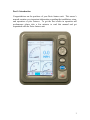
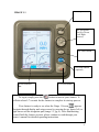
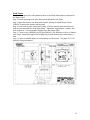
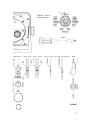
Faria Instruments IS0250a is an advanced multi-function display that provides boaters with a wide range of information and control options. With its customizable gauge screens, users can tailor the display to their specific needs, choosing from a variety of data points including speed, fuel level, depth, and air temperature. The Fuel Flow Manager helps boaters optimize their fuel consumption, while the optional Radio Control Screen provides convenient control over compatible marine radios.
Faria Instruments IS0250a is an advanced multi-function display that provides boaters with a wide range of information and control options. With its customizable gauge screens, users can tailor the display to their specific needs, choosing from a variety of data points including speed, fuel level, depth, and air temperature. The Fuel Flow Manager helps boaters optimize their fuel consumption, while the optional Radio Control Screen provides convenient control over compatible marine radios.


-
 1
1
-
 2
2
-
 3
3
-
 4
4
-
 5
5
-
 6
6
-
 7
7
-
 8
8
-
 9
9
-
 10
10
-
 11
11
-
 12
12
-
 13
13
-
 14
14
-
 15
15
-
 16
16
-
 17
17
-
 18
18
-
 19
19
-
 20
20
-
 21
21
-
 22
22
-
 23
23
-
 24
24
-
 25
25
-
 26
26
-
 27
27
-
 28
28
-
 29
29
-
 30
30
-
 31
31
-
 32
32
-
 33
33
-
 34
34
-
 35
35
-
 36
36
-
 37
37
-
 38
38
-
 39
39
-
 40
40
-
 41
41
-
 42
42
-
 43
43
-
 44
44


Faria Instruments IS0250a User manual
- Type
- User manual
- This manual is also suitable for
Faria Instruments IS0250a is an advanced multi-function display that provides boaters with a wide range of information and control options. With its customizable gauge screens, users can tailor the display to their specific needs, choosing from a variety of data points including speed, fuel level, depth, and air temperature. The Fuel Flow Manager helps boaters optimize their fuel consumption, while the optional Radio Control Screen provides convenient control over compatible marine radios.
Ask a question and I''ll find the answer in the document
Finding information in a document is now easier with AI
Related papers


Other documents
-
Toro Temperature Sender Kit, Groundsmaster 1000L Installation guide
-
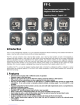 MGL Avionics FF-1 Operating instructions
-
Evinrude I-command User manual
-
3D Systems Geomagic Touch Quick start guide
-
Intermec EZBuilder Supplementary Manual
-
Intermec CV30 User manual
-
Intermec T2420 User manual
-
Intermec Trakker Antares 2475 System Manual
-
-
Intermec 200 System Manual
