Page is loading ...

User Guide
IN1804 Series
Scalers
Seamless Scaling Switchers
68-3274-01 Rev. C
02 20

Safety Instructions
Safety Instructions • English
WARNING: This symbol, , when used on the product, is intended to
alert the user of the presence of uninsulated dangerous voltage within the
product’s enclosure that may present a risk of electric shock.
ATTENTION: This symbol, , when used on the product, is intended
to alert the user of important operating and maintenance (servicing)
instructions in the literature provided with the equipment.
For information on safety guidelines, regulatory compliances, EMI/EMF
compatibility, accessibility, and related topics, see the Extron Safety and
Regulatory Compliance Guide, part number 68-290-01, on the Extron
website, www.extron.com.
Sicherheitsanweisungen • Deutsch
WARNUNG: Dieses Symbol auf dem Produkt soll den Benutzer darauf
aufmerksam machen, dass im Inneren des Gehäuses dieses Produktes
gefährliche Spannungen herrschen, die nicht isoliert sind und die einen
elektrischen Schlag verursachen können.
VORSICHT: Dieses Symbol auf dem Produkt soll dem Benutzer in
der im Lieferumfang enthaltenen Dokumentation besonders wichtige
Hinweise zur Bedienung und Wartung (Instandhaltung) geben.
Weitere Informationen über die Sicherheitsrichtlinien, Produkthandhabung,
EMI/EMF-Kompatibilität, Zugänglichkeit und verwandte Themen finden Sie in
den Extron-Richtlinien für Sicherheit und Handhabung (Artikelnummer
68-290-01) auf der Extron-Website, www.extron.com.
Instrucciones de seguridad • Español
ADVERTENCIA: Este símbolo, , cuando se utiliza en el producto,
avisa al usuario de la presencia de voltaje peligroso sin aislar dentro del
producto, lo que puede representar un riesgo de descarga eléctrica.
ATENCIÓN: Este símbolo, , cuando se utiliza en el producto, avisa
al usuario de la presencia de importantes instrucciones de uso y
mantenimiento recogidas en la documentación proporcionada con el
equipo.
Para obtener información sobre directrices de seguridad, cumplimiento
de normativas, compatibilidad electromagnética, accesibilidad y temas
relacionados, consulte la Guía de cumplimiento de normativas y seguridad
de Extron, referencia 68-290-01, en el sitio Web de Extron, www.extron.com.
Instructions de sécurité • Français
AVERTISSEMENT : Ce pictogramme, , lorsqu’il est utilisé sur le
produit, signale à l’utilisateur la présence à l’intérieur du boîtier du
produit d’une tension électrique dangereuse susceptible de provoquer
un choc électrique.
ATTENTION : Ce pictogramme, , lorsqu’il est utilisé sur le produit,
signale à l’utilisateur des instructions d’utilisation ou de maintenance
importantes qui se trouvent dans la documentation fournie avec le
matériel.
Pour en savoir plus sur les règles de sécurité, la conformité à la
réglementation, la compatibilité EMI/EMF, l’accessibilité, et autres sujets
connexes, lisez les informations de sécurité et de conformité Extron, réf.
68-290-01, sur le site Extron, www.extron.com.
Istruzioni di sicurezza • Italiano
AVVERTENZA: Il simbolo, , se usato sul prodotto, serve ad
avvertire l’utente della presenza di tensione non isolata pericolosa
all’interno del contenitore del prodotto che può costituire un rischio di
scosse elettriche.
ATTENTZIONE: Il simbolo, , se usato sul prodotto, serve ad avvertire
l’utente della presenza di importanti istruzioni di funzionamento e
manutenzione nella documentazione fornita con l’apparecchio.
Per informazioni su parametri di sicurezza, conformità alle normative,
compatibilità EMI/EMF, accessibilità e argomenti simili, fare riferimento
alla Guida alla conformità normativa e di sicurezza di Extron, cod. articolo
68-290-01, sul sito web di Extron, www.extron.com.
I

Copyright
© 2018-2020 Extron Electronics. All rights reserved. www.extron.com
Trademarks
All trademarks mentioned in this guide are the properties of their respective owners.
The following registered trademarks (
®
), registered service marks (
SM
), and trademarks (
TM
) are the property of RGBSystems, Inc. or
ExtronElectronics (see the current list of trademarks on the Terms of Use page at www.extron.com):
Registered Trademarks
(
®
)
Extron, Cable Cubby, ControlScript, CrossPoint, DTP, eBUS, EDID Manager, EDID Minder, Flat Field, FlexOS, Glitch Free. Global
Configurator, GlobalScripter, GlobalViewer, Hideaway, HyperLane, IPIntercom, IPLink, KeyMinder, LinkLicense, LockIt, MediaLink,
MediaPort, NetPA, PlenumVault, PoleVault, PowerCage, PURE3, Quantum, ShareLink, Show Me, SoundField, SpeedMount, SpeedSwitch,
StudioStation, SystemINTEGRATOR, TeamWork, TouchLink, V-Lock, VideoLounge, VN-Matrix, VoiceLift, WallVault, WindoWall, XPA, XTP,
XTPSystems, and ZipClip
Registered Service Mark
(SM)
: S3 Service Support Solutions
Trademarks
(
™
)
AAP, AFL (Accu-RATEFrameLock), ADSP(Advanced Digital Sync Processing), Auto-Image, AVEdge, CableCover, CDRS(ClassD
Ripple Suppression), Codec Connect, DDSP(Digital Display Sync Processing), DMI (DynamicMotionInterpolation), DriverConfigurator,
DSPConfigurator, DSVP(Digital Sync Validation Processing), eLink, EQIP, Everlast, FastBite, Flex55, FOX, FOXBOX, IP Intercom
HelpDesk, MAAP, MicroDigital, Opti-Torque, PendantConnect, ProDSP, QS-FPC(QuickSwitch Front Panel Controller), RoomAgent,
Scope-Trigger, SIS, SimpleInstructionSet, Skew-Free, SpeedNav, Triple-Action Switching, True4K, True8K, Vector™ 4K, WebShare, XTRA,
and ZipCaddy

FCC Class A Notice
This equipment has been tested and found to comply with the limits for a Class A digital
device, pursuant to part15 of the FCC rules. The ClassA limits provide reasonable
protection against harmful interference when the equipment is operated in a commercial
environment. This equipment generates, uses, and can radiate radio frequency energy
and, if not installed and used in accordance with the instruction manual, may cause
harmful interference to radio communications. Operation of this equipment in a
residential area is likely to cause interference. This interference must be corrected at the
expense of the user.
ATTENTION:
• The Twisted Pair Extension technology works with unshielded twisted pair (UTP)
or shielded twisted pair (STP) cables; but to ensure FCC Class A and CE
compliance, STP cables and STP Connectors are required.
• La technologie extension paires torsadées fonctionne avec les câbles paires
torsadées blindées(UTP) ou non blindées(STP). Afin de s’assurer de la
compatibilité entre FCC ClasseA et CE, les câbles STP et les connecteurs STP
sont nécessaires.
NOTES: For more information on safety guidelines, regulatory compliances, EMI/EMF
compatibility, accessibility, and related topics, see the Extron Safety and Regulatory
Compliance Guide on the Extron website.
VCCI-A Notice
この装置は、クラスA情報技術装置です。 この装置を家庭環境で使用すると、電波妨害を引き
起こすことがあります。 その場合には使用者が適切な対策を講ずるよう要求されることがあります。
VCCI-A
Battery Notice
This product contains a battery. Do not open the unit to replace the battery. If the
battery needs replacing, return the entire unit to Extron (for the correct address, see the
Extron Warranty section on the last page of this guide).
CAUTION: Risk of explosion. Do not replace the battery with an incorrect type. Dispose
of used batteries according to the instructions.
ATTENTION : Risque d’explosion. Ne pas remplacer la pile par le mauvais type de pile.
Débarrassez-vous des piles usagées selon le mode d’emploi.

Conventions Used in this Guide
Notifications
The following notifications are used in this guide:
CAUTION: Risk of minor personal injury.
ATTENTION : Risque de blessuremineure.
ATTENTION:
• Risk of property damage.
• Risque de dommages matériels.
NOTE: A note draws attention to important information.
TIP: A tip provides a suggestion to make working with the application easier.
Software Commands
Commands are written in the fonts shown here:
^AR Merge Scene,,0p1 scene 1,1 ^B 51 ^W^C.0
[01] R 0004 00300 00400 00800 00600 [02] 35 [17] [03]
E X! *X1&* X2)* X2#* X2! CE}
NOTE: For commands and examples of computer or device responses used in this
guide, the character “0” is the number zero and “O” is the capital letter “o.”
Computer responses and directory paths that do not have variables are written in the
font shown here:
Reply from 208.132.180.48: bytes=32 times=2ms TTL=32
C:\Program Files\Extron
Variables are written in slanted form as shown here:
ping xxx.xxx.xxx.xxx —t
SOH R Data STX Command ETB ETX
Selectable items, such as menu names, menu options, buttons, tabs, and field names
are written in the font shown here:
From the File menu, select New.
Click the OK button.
Specifications Availability
Product specifications are available on the Extron website, www.extron.com.
Extron Glossary of Terms
A glossary of terms is available at http://www.extron.com/technology/glossary.aspx.


viiIN1804 Seamless Scaling Switchers • Contents
Contents
Introduction ...................................................1
About this Guide ................................................. 1
Product Description ............................................ 1
Models ........................................................... 1
Integrated Digital Twisted Pair Extension ......... 2
Features ............................................................. 2
Control Methods ................................................. 6
Application Diagrams .......................................... 7
Installation ..................................................... 9
Installation Overview ........................................... 9
Rear Panel Connections ................................... 10
Connection Details ........................................... 16
Analog Audio Connections ........................... 16
HDMI Connections ....................................... 17
Twisted Pair Recommendations for DTP2,
XTP, and HDBaseT Communication ............. 18
Wiring the Contact/Tally Connectors ............. 19
Connecting through an SM Cable ................. 20
Operation ..................................................... 21
Front Panel Overview ........................................ 21
Powering Up .................................................... 22
Selecting an Input ............................................. 22
Using the On-Screen Menu System .................. 22
Menu Selection Buttons ................................ 22
Menu Overview ............................................. 23
Using the Menu Screens ............................... 24
Device Info Screen ........................................ 25
Quick Setup Submenu.................................. 26
Picture Controls Submenu ............................ 27
Input Submenu ............................................. 29
Output Submenu .......................................... 32
Audio Submenu ............................................ 35
Advanced Submenu ..................................... 37
Communication Submenu ............................ 40
Front Panel Lockout (Executive Modes) ............ 41
Input Presets .................................................... 42
Reset Modes .................................................... 42
RS-232 and IR Signal Insertion ......................... 43
Ethernet to RS-232 Insertion ........................ 44
Captive Screw IR Signal Insertion ................. 46
Unidirectional RS-232 Insertion via SIS
Commands ................................................. 47
SIS Configuration and Control ........................ 48
Host and Switcher Communication .................. 48
Copyright Information ................................... 48
Password Messages .................................... 49
Switcher-Initiated Messages ......................... 50
Error Responses ........................................... 50
SIS Overview .................................................... 51
Using the Command and Response Tables .. 51
Symbol Definitions ........................................ 51
Command and Response Tables for IN1804
SIS Commands ............................................... 60
Configuration Software ..................................... 82
Software Installation.......................................... 82
Software Download Center Page .................. 82
Software Connection ........................................ 84
Device Discovery Panel ................................. 84
TCP/IP Panel ................................................ 85
Offline Device Preview ................................... 86
Software Overview ............................................ 87
Software Menu ............................................. 87
Device Menu................................................. 90

IN1804 Seamless Scaling Switchers • Contents viii
Internal Web Page .............................................. 92
Accessing the Web Page .................................. 92
Disabling Compatibility Mode ........................ 93
Web Page Components ................................... 94
Device Info Panel .......................................... 95
Inputs Panel.................................................. 95
Roles and Permissions Panel ........................ 96
Device Status Panel ...................................... 97
Outputs Panel ............................................... 99
Firmware Panel ............................................. 99
Network Settings Panel .............................. 100
RS-232 Panel ............................................. 101
Reference Information ............................. 102
Mounting ........................................................ 102
Tabletop Mounting ...................................... 102
Rack Mounting ........................................... 102
Furniture Mounting...................................... 103
Downloading Updated Firmware ..................... 103
Licensed Third-Party Software Used in the
Switchers ...................................................... 104

IN1804 Seamless Scaling Switchers • Introduction 1
Introduction
This section provides general information about this guide and the Extron IN1804. Topics in
this section include:
• About this Guide
• Product Description
• Features
• Application Diagrams
• Control Methods
About this Guide
This guide describes how to install, configure, and operate the unit.
In this guide, the terms “switcher” and “IN1804” are used interchangeably to refer to all
IN1804 models. The term “standard model” refers to the basic IN1804 containing no
twisted pair input or output. “Twisted pair models” refers to the IN1804 DI, IN1804 DO, and
IN1804 DI/DO.
Product Description
The Extron IN1804 is a compact, four input seamless scaling switcher that supports signal
resolutions up to 4K @ 60 Hz, with 4:4:4 chroma sampling. It incorporates Extron-patented
Vector 4K scaling technology specifically engineered for 4K signal processing applications.
It features DisplayPort and HDMI inputs with DI, DO, and DI/DO models that provide Extron
DTP2 extension of video, audio, and control signals up to 330 feet (100 meters) over a
shielded CATx twisted pair cable.
The IN1804 Series also provide automatic switching, audio embedding and de-embedding,
seamless transition effects, and logo keying. Designed for professional AV integration, the
IN1804 can be controlled and configured via Ethernet, RS-232, USB, and contact closure
with tally outputs.
Models
The IN1804 is available in the following models:
Model Description
IN1804 Standard model Inputs: 1 DisplayPort, 3 HDMI
Outputs: 2 HDMI
IN1804 DI DTP2 input Inputs: 1 DisplayPort, 2 HDMI, 1 DTP2/XTP
Outputs: 2 HDMI
IN1804 DO DTP2 output Inputs: 1 DisplayPort, 3 HDMI
Outputs: 1 DTP2/XTP/HDBT, 1 HDMI
IN1804 DI/DO DTP2 input and output Inputs: 1 DisplayPort, 2 HDMI, 1 DTP2/XTP
Outputs: 1 DTP2/XTP/HDBT, 1 HDMI

IN1804 Seamless Scaling Switchers • Introduction 2
Integrated Digital Twisted Pair Extension
The DTP2 inputs and outputs are proprietary signals that are created within any of
the Extron DTP Extender systems and transmitted over a single shielded twisted pair
(STP) cable. The IN1804 accepts DTP inputs from transmitting devices such as the
DTP T USW 333.
NOTE: Extron XTP DTP 24 shielded twisted pair cable is strongly recommended for
optimal performance.
• The IN1804 DI and IN1804 DI/DO can receive signals from remote DTP or DTP2
transmitters at a conference table, lectern, or wall.
• The IN1804 DO and IN1804 DI/DO can transmit to a DTP or DTP2 receiver or directly to
an HDBaseT enabled display device.
All twisted pair models can be integrated into an XTP II matrix switcher system. Additionally,
they can send power to selected DTP or DTP2 endpoints over the same shielded CATx
cable, streamlining system design and installation.
DTP transmitters and receivers are available in compact, low-profile enclosures, plus
decorator-style wallplate and floorbox versions to suit the installation requirements of a
specific application.
RS-232 and IR signal insertion
Bidirectional RS-232 and IR signals can be inserted from a control system and transmitted
over the single shielded CATx cable together with the video and audio, enabling control of
a source or display. The DTP2/XTP/HDBT output on IN1804 DO and IN1804 DI/DO can
be configured for compatibility with HDBaseT-enabled displays to send digital video and
embedded audio, plus bidirectional RS-232 and IR signals up to 330 feet (100 meters) over
a shielded CATx cable.
Matrix switcher integration
In addition to supporting DTP endpoints, the IN1804 twisted pair models can be integrated
into an XTP CrossPoint matrix switcher system. This enables facility-wide AV system
applications with a centralized AV signal distribution infrastructure, as well as several
presentation spaces with local AV switching and processing.
Features
• Integration of DisplayPort, HDMI, and audio sources into presentation
systems — All IN1804 models provide centralized switching for a wide range of AV
sources.
• DisplayPort, HDMI, and optional DTP2 inputs —
• IN1804 standard and IN1804 DO models feature one DisplayPort and three HDMI
inputs.
• The IN1804 DI and IN1804 DI/DO feature two HDMI, one DisplayPort, and one
DTP2 input.
• HDMI and optional DTP2 outputs —
• The IN1804 and IN1804 DI models feature dual mirrored HDMI outputs.
• The IN1804 DO and IN1804 DI/DO feature one DTP2 output and one mirrored
HDMI output.

IN1804 Seamless Scaling Switchers • Introduction 3
• Advanced Extron Vector 4K scaling engine — The Vector 4K scaling engine is
specifically designed for critical-quality 4K imagery, with best-in-class image upscaling
and downscaling.
• Supports signal resolutions up to 4K @ 60 Hz with 4:4:4 color sampling.
• Supports DisplayPort Single Stream Transport (SST) data rates up to 21.6 Gbps.
• Supports HDMI 2.0 specification features — Features include data rates up to
18 Gbps, Deep Color, and HD lossless audio formats.
• Logo image keying and display — A logo graphic can be positioned and keyed over
the live video output. Logo graphics in BMP, GIF, JPG, PNG, or TIFF format can be
uploaded to the unit. Full screen images up to 4K resolution can also be displayed to
eliminate loss of video between presentations.
• Selectable seamless switching transitions — Seamless cut and fade, cut through
black, and fade through black transition effects are available.
• Auto-switching between inputs — Auto-input switching allows for unmanaged
installation in locations such as in a lectern or under a conference table. When multiple
inputs are active, the switching priority is configurable, including last-connected input
and user-selectable priority.
• HDCP 2.2 compliant — Ensures display of content-protected 4K video media and
maintains interoperability with earlier versions of HDCP.
• Stereo audio embedding — Analog audio signals can be embedded onto the DTP2
or HDMI output.
• Stereo audio de-embedding — Embedded HDMI two-channel PCM audio can be
extracted to the analog outputs, or multi-channel bitstream formats can be passed to
the DTP2 or HDMI output.
• Displays user-supplied images for screen saver, corporate branding, logo
insertion, and HDCP notification — Custom, user-loaded images can be displayed
as a screen saver after a predefined duration of inactivity at the video input, or whenever
the input is disconnected between presentations. User-supplied images can also
be displayed for HDCP Visual Confirmation, whenever HDCP-encrypted content is
transmitted to a non-HDCP compliant display. A user-loaded image can be displayed as
a corporate logo at any time during the video.
• Consumer Electronics Control (CEC) capability — Standard, built-in CEC
commands can be triggered to control displays or other AV devices connected to the
HDMI or DTP2 outputs. The ability to control specific functions, such as power on and
off, input selection, or volume level, is dependent on implementation by the device
manufacturer.
• Integrated DTP2 extension — IN1804 DI and IN1804 DI/DO feature one DTP2/XTP
input. The IN1804 DO and IN1804 DI/DO feature one DTP2/XTP/HDBT output, which
support transmission of video, audio, and control up to 330 feet (100 meters) over a
shielded CATx cable.
• Compatible with CATx shielded twisted pair cable — IN1804 DI,
IN1804 DO, and IN1804 DI/DO support a maximum transmission distance of
330 feet (100 meters) for all compatible resolutions when used with CATx shielded
twisted pair cable. Shielded twisted pair cabling with solid center conductor sizes of
24 AWG or better is recommended for optimal performance.
• Remote powering of DTP transmitter or receiver — IN1804 DI, IN1804 DO,
and IN1804 DI/DO can provide power to a DTP or DTP2 endpoint over the twisted
pair connection, eliminating the need for a separate power supply at the remote
unit.

IN1804 Seamless Scaling Switchers • Introduction 4
• RS-232 insertion from the Ethernet control port — Saves system resources
and simplifies installation by enabling a control processor to access remote RS-232
devices over Ethernet.
• Additional analog stereo audio signals accepted — IN1804 DI, IN1804 DO,
and IN1804 DI/DO support stereo analog audio signals for simultaneous
transmission over the same shielded twisted pair cable.
• Bidirectional RS-232 and IR pass-through for AV device control —
Bidirectional RS-232 control and IR signals can be transmitted alongside the video
signal over the DTP connection, allowing the remote device to be controlled without
additional cabling. Bidirectional control extension eliminates control system wiring to
remote devices.
• Compatible with all DTP-enabled products, plus XTP CrossPoint matrix
switchers — Enables mixing and matching with desktop and wallplate endpoints,
as well as other DTP or DTP2-enabled products to meet application requirements.
The twisted pair models can be integrated with XTP II matrix switchers to provide
connectivity between presentation spaces and a larger, facility-wide system.
• DTP2 output compatible with HDBaseT-enabled devices — The IN1804 DO
and IN1804 DI/DO can be configured to send video and embedded audio, plus
bidirectional RS-232 and IR signals, to an HDBaseT-enabled display.
• RJ-45 signal and link LED indicators for DTP port — Provides a means for
validating signal flow and operation, allowing quick identification of connectivity
issues.
• User-selectable HDCP authorization — Allows inputs 2 through 4 to appear HDCP
compliant or non-HDCP compliant to the connected source, which is beneficial if the
source automatically encrypts all content when connected to an HDCP-compliant
device. Protected material is not passed in non-HDCP mode.
• Key Minder continuously verifies HDCP compliance — Key Minder authenticates
and maintains continuous HDCP encryption between input and output devices to
ensure quick and reliable switching in professional AV environments, while enabling
simultaneous distribution of a single source signal to one or more displays.
• EDID Minder manages EDID communication between connected devices —
EDID Minder ensures the source powers up properly and reliably outputs content for
display.
• Custom EDID and output resolutions supported — User-defined scaling output
resolutions can be supported by uploading custom EDID files, or capturing EDID from a
display or other destination device.
• HDCP authentication and signal presence confirmation — Provides real-time
verification of HDCP status for each digital video input and output. This allows for
simple, quick, and easy signal and HDCP verification through RS-232, USB, or
Ethernet, providing feedback to a system operator or helpdesk support staff.
• HDCP Visual Confirmation — A full-screen green signal is sent when
HDCP-encrypted content is transmitted to a non-HDCP compliant display, providing
immediate visual confirmation that protected content cannot be viewed on the display.
• Aspect ratio control — The aspect ratio of the video output can be controlled by
selecting a fill mode, which provides a full screen output, or a follow mode, which
preserves the original aspect ratio of the input signal.
• Motion-adaptive deinterlacing for signals up to 1080i — Advanced deinterlacing
for all interlaced signals up to 1080i delivers optimized image quality.

IN1804 Seamless Scaling Switchers • Introduction 5
• Automatic 3:2 and 2:2 pulldown detection — Advanced film mode processing
techniques help maximize image quality for content sources that originated from film.
• Auto-Image setup — When Auto-Image is activated, the unit automatically optimizes
the image by analyzing and adjusting to the video input signal.
• Auto Input Memory — When Auto Input Memory is activated, the unit stores size,
position, and picture settings based on the incoming signal. When the same signal is
detected again, these image settings are recalled from memory.
• Input presets — Memory presets are available to store and recall optimized image
settings.
• Output muting control — The video and audio output can be muted independently.
• Image freeze control — A live image can be frozen using RS-232, USB, or Ethernet
control.
• On-screen menus — Intuitive on-screen menus allow for easy system setup using
the front panel controls. Key parameters such as input and output video formats are
conveniently grouped on the initial Quick Setup screen, while additional screens provide
full control over the unit’s other functions and settings.
• Picture controls — Controls are provided for brightness, contrast, and detail, as well
as horizontal and vertical sizing, and positioning.
• Internal video test patterns and pink noise generator — All IN1804 models offer
several video test patterns and audio pink noise to facilitate proper system setup and
calibration of display devices.
• HDMI to DVI Interface Format Correction — Automatically enables or disables
embedded audio and InfoFrames, and sets the correct color space for proper
connection to HDMI and DVI displays.
• Color bit depth management — Automatically adjusts color bit depth based on the
display EDID, preventing color compatibility conflicts between source and display.
• Audio file playback — Up to 16 prerecorded messages may be stored and played
back over the program audio output.
• Output volume control — Provides master volume control for the analog line level
output, two-channel PCM HDMI audio, and DTP analog audio for the IN1804 DO and
IN1804 DI/DO models.
• Audio input gain and attenuation — Gain or attenuation can be adjusted for the
analog audio input to eliminate noticeable differences when switching between sources.
• Audio switching transitions — The audio output level automatically ramps down and
then ramps up to match the video during switching transitions.
• Integrated audio delay — The audio output is automatically delayed to compensate
for latency introduced by the video processing.
• Audio input assignment — The audio input can be associated with one or more video
inputs.
• Multiple embedded audio formats — All IN1804 models are compatible with a broad
range of multi-channel audio signals, providing reliable operation with HDMI sources.
• Output Standby Mode — All models can be set to automatically mute video and sync
output to the display device when no active input signal is detected. This allows the
projector or flat-panel display to automatically enter into standby mode to save energy
and enhance lamp or panel life.
• Power Save Mode — All IN1804 models can be placed in a low power standby state
to conserve energy when not in use.

IN1804 Seamless Scaling Switchers • Introduction 6
• Front panel security lockout — This feature locks out all front panel functions. All
functions, however, are available through Ethernet, USB, or RS-232 control.
• Ethernet monitoring and control — Enables control and proactive monitoring over a
LAN or WAN.
• Built-in web pages — Enables the use of a standard browser for device monitoring
and troubleshooting over an intuitive web interface.
• RS-232 control port — Enables the use of serial commands for integration into
a control system. Extron products use the Simple Instruction Set (SIS) command
protocol, a set of basic ASCII commands that allow for quick and easy programming.
• Contact closure remote control with tally output — Contact closure ports enable
remote video input selection control, while tally outputs provide +5 VDC to illuminate
LEDs for video input identification. The contact and tally ports may be configured for
independent use when the IN1804 is connected to an external control processor.
• Compatible with Teamwork Show Me Cables — Show Me cables provide
convenient connectivity and user input selection and control for TeamWork
Collaboration Systems.
• Front panel USB configuration port — Enables easy system configuration without
having to access the rear panel.
• Front panel LED indicators for signal presence, HDCP status, and power —
Provides visual indication of system status for real-time feedback and monitoring of key
performance parameters.
• Extron Product Configuration Software (PCS) — The PCS program enables
configuration of multiple products using a single software application.
• Compact 1U, half rack width metal enclosure — The half rack width enclosure
can be mounted under furniture using the UTS Series Under Table Shelf System or
MBU 123 Low Profile Mount Kit, available separately.
• Includes LockIt HDMI cable lacing brackets
• Internal Extron Everlast power supply — Provides worldwide power compatibility,
with high-demonstrated reliability and low power consumption for reduced operating
cost. The Extron Everlast Power Supply is covered by a 7-year parts and labor warranty.
Control Methods
Control the IN1804 series switchers using one or more of the following methods:
• The front panel controls and the on-screen display (OSD) menu (see Using the
On-Screen Menu System on page 22).
• A computer, a touch screen panel, or any other device that sends and receives
serial communications through the USB, RS-232, or Ethernet port. Use the Extron
DataViewer utility on the computer to enter SIS commands (see SIS Configuration
and Control beginning on page 48).
• The Extron Product Configuration Software (PCS) on a computer with a Windows
®
operating system (see Configuration Software beginning on page 82 and the IN1804
Series PCS Help File).
• Internal web pages, providing a web browser-based interface for monitoring the
switcher from a computer over a LAN network (see Internal Web Page beginning on
page 92).

IN1804 Seamless Scaling Switchers • Introduction 7
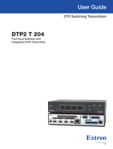
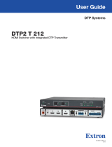
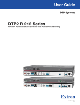
Application Diagrams
The following diagrams show examples of typical applications for different IN1804 models.
21
1
100-240V ~0.7A MAX
50-60 Hz
LIN
R
LOUT
R
Tx Rx G
CT
2
CT
3
CT
4
CT
5
CT
6
CT
7
CT GV+
RS-232
RESET
LAN
3 4 1A
HDMI/CEC
1B
HDMI/CEC
OUTPUTS
REMOTE
AUDIO
CONTACT
/TALLY
INPUTS
POWER
12V
1A MAX
G
Tx Rx RTSCTS
COM 1
G
Tx Rx
COM 2
VCG
VOL
RELAYS
1 2 C
1 2 3 4 G
DIGITAL I/O
PWROUT = 6W
eBUS
+V +S
-S
G
LAN
IPCP PRO 250
IR/S
S G
ShareLink 250 W
AUDIO
OUT
LAN / PoE
VGA OUT HDMI OUT
USB 3
POWER
5V
2.3A MAX
MODEL 80
FLAT PANEL
WiFi
1234
PCSHARELINKON/OFF
PRESS PRESS
USB CHARGER
125 VAC. 50-60 Hz 12A MAX
Extron
Sh
ow Me Cable
Extron
ShareLink 250 W
Wireless Collaboration
Gateway
Wireless
DisplayPort
HDMI
HDMI
RS-232
Extron IN1804
Seamless
Scaling Switcher
Display
Extron
IPCP Pro 250
Control Processor
PC
Laptop
Tablet
Smartphone
Extron
Cable Cubby 500 CCB
Cable Access Enclosure
Figure 1. IN1804 Standard Model Application Example — Teamwork System
ShareLink 250 W
AUDIO
OUT
LAN / PoE
VGA OUT HDMI OUT
USB 3
POWER
5V
2.3A MAX
POWER
12V
1A MAX
G
Tx Rx RTSCTS
COM 1
G
Tx Rx
COM 2
VCG
VOL
RELAYS
12C
1 2 3 4G
DIGITAL I/O
PWR OUT =6W
eBUS
+V +S
-S
G
LAN
IPCP PRO 250
IR/S
SG
POWER
12V
1A MAX
AUDIO
INPUTS
SIG LINK
DTP2 OUT
OVER DTP2
RS-232
IR
Tx Rx Tx RxG
21
1
100-240V ~1.0A MAX
50-60 Hz
LIN
R
LOUT
R
Tx Rx G
CT
2
CT
3
CT
4
CT
5
CT
6
CT
7
CT GV+
RS-232
Tx Rx G
IR
RESET
LAN
3 41A
HDMI/CEC
1B
HDMI/CEC
OUTPUTS
REMOTE
AUDIO
CONTACT
/TALLY
INPUTS
OVER TP
SIG
IN
LINK
Extron
IN1804 DI
Seamless Scalin
g
Switcher
Extron
DTP2 T 211
Transmitter
Extron
IPCP Pro 250
Control Processor
Extron
TLP Pro 725T
7
" Tabletop
TouchLink Pro
Touchpanel
Ethernet
Ethernet
Ethernet/PoE
CATx Cable
up to 330' (100 m)
HDMI/
CEC
HDMI/
CEC
HDMIDisplayPort
LAN
LAN
HDMI
4K Display
Laptop
Laptop
Tablet
MODEL 80
FLAT PANEL
4K Display
MODEL 80
FLAT PANEL
HDMI
Computer
1
4K Media Player
Extron
ShareLink 250 W
Wireless Collaboration
Gateway
Smartphone
Figure 2. IN1804 DI Meeting Room Application Example
1
2

IN1804 Seamless Scaling Switchers • Introduction 8
L
RS-323 IR
Tx Rx Tx RxG
R
POWER
12V
--A MAX
AUDIO
OUTPUTS
OVER DTP2
SIG LINK
DTP2 IN
21
1
100-240V ~1.0A MAX
50-60 Hz
LIN
R
L OUT
R
Tx Rx G
CT
2
CT
3
CT
4
CT
5
CT
6
CT
7
CT GV+
RS-232
RESET
LAN
3 4 1B
HDMI/CEC
OUTPUTS
REMOTE
AUDIO
CONTACT
/TALLY
INPUTS
Tx Rx G
IR
1A
OVER TP
SIG
OUT
LINK
Extron
IN1804 DO
Seamless Scaling
Switcher
Extron
DTP2 R 211
Receiver
Ethernet
CATx Cable
up to 330'
(100 m)
HDMI/CEC
HDMIHDMIHDMI
DisplayPort
LAN
HDMI/CEC
4K Display
Laptop
Laptop
MODEL 80
FLAT PANEL
4K Display
MODEL 80
FLAT PANEL
Computer
1
4K Media Player
Figure 3. IN1804 DO Training Room Application Example
IN1804 DI/DO
SIGNAL
1
3
2
4
STATUS
MENU
ENTER
INPUT 1
INPUT 2
INPUT 3
INPUT 4
CONFIG
HDCP IN
HDCP OUT 1A
HDCP OUT 1B
AUTO SW
HOLDFOR 720p/1080p
MODEL 80
FLAT PANEL
LAN
LAN
1000
LINK
ACT
R
IR
IPCP PRO 250
eBUS
OVER
LIMIT
S
COM
I/O
1
2
2
4
1
321
RTS
CTS
Tx
Rx
RELAYS
IR/S
DTP2 R 212 SERIES
CONFIG
AUTO
SWITCH
INPUTS
OUTPUT
12
SIGNAL
HDCP
INPUTS
1
MODE NORM/ AUTO
2
ShareLink Pro 1000
HD WIN
STANDBY
SCREEN
DECODER
HD PASS
HDMIDECODER
SIGNAL
HDCP
CONFIG
OUTPUTINPUT
HDMI
WINDOW
HDMI
PASS-THROUGH
12
USB
INPUT
OFF
SEND
POWER
STATUS
OUTPUT
LINK
DTP2 T 211
CONFIG
Extron
SM 3
Surface Mount
Speakers
Laptop with 4K
Video Output
Laptop with 4K
Video Output
Local 4K
Monitor
DisplayPort
Ethernet
HDMI
HDMI
CATx Cable up to 330' (100 m)
CATx Cable
up to 330'
(100 m)
Ext
ron
IN
1804 DI/DO
Seamless Scaling Switcher
Audio
Laptop
HDMI
Tablet
Smartphone
Extron
DTP2 R 212 SA
Receiver
4K Display
RS-232
Ethernet
Ethernet
Ethernet
Ethernet
HDMI
EE
Extron
IPCP Pro 250
Control Processo
r
Extron
ShareLink Pro 1000
Collaboration
Gateway
Extron
DTP2 T 211
Transmitter
Facility/Room
Wireless Access Point
Figure 4. IN1804 DI/DO Application Example
3
4

IN1804 Seamless Scaling Switchers • Installation 9
Installation
This section contains information on how to connect cables to the IN1804 models. Topics in
this section include:
• Installation Overview
• Rear Panel Connections
• Connection Details
Installation Overview
1. Turn off or disconnect all related equipment. Ensure that video sources and output
displays are all turned off and disconnected from the power source.
2. Mount the switcher (see Mounting on page 102).
3. Connect input sources (see Rear Panel Connections on page 10).
4. Connect output devices (see Rear Panel Connections).
5. Connect desired control devices (see Rear Panel Connections).
6. (Optional) Connect contact closure and tally indicator devices and any needed Show
Me cables (see Wiring the Contact/Tally Connectors on page 19).
7. Connect a power source to the switcher (see AC power connector on page 11).
8. Configure the switcher using any of the following methods:
• Front panel menus (see Operation beginning on page 21)
• PCS (see Configuration Software beginning on page 82 to download the
software, and see the IN1804 Series PCS Help File to configure the system)
• SIS commands (see SIS Configuration and Control, beginning on page 48)

IN1804 Seamless Scaling Switchers • Installation 10
Rear Panel Connections
Figures 5 through 8 show the rear panels of the four IN1804 models: IN1804 (standard),
IN1804 DI, IN1804 DO, and IN1804 DI/DO.
21
1
100-240V ~0.7A MAX
50-60 Hz
LIN
R
L OUT
R
Tx Rx G
CT
2
CT
3
CT
4
CT
5
CT
6
CT
7
CT GV+
RS-232
RESET
LAN
3 4 1A
HDMI/CEC
1B
HDMI/CEC
OUTPUTS
REMOTE
AUDIO
CONTACT
/TALLY
INPUTS
A
C
H
B
I
J
K
M
Q
L
N
O
P
Figure 5. IN1804 Standard Rear Panel
21
1
100-240V~1.0A MAX
50-60 Hz
LIN
R
L OUT
R
Tx Rx G
CT
2
CT
3
CT
4
CT
5
CT
6
CT
7
CT GV+
RS-232
Tx Rx G
IR
RESET
LAN
3
41
A
HDMI/CEC
1B
HDMI/CEC
OUTPUTS
REMOTE
AUDIO
CONTACT
/TALLY
INPUTS
OVER TP
SIG
IN
LINK
A
D
C
E
H
I
K J
M
Q
L
N
B
O
P
Figure 6. IN1804 DI Rear Panel
21
1
100-240V~1.0A MAX
50-60 Hz
LIN
R
LOUT
R
Tx Rx G
CT
2
CT
3
CT
4
CT
5
CT
6
CT
7
CT GV+
RS-232
RESET
LAN
3 4 1B
HDMI/CEC
OUTPUTS
REMOTE
AUDIO
CONTACT
/TALLY
INPUTS
Tx Rx G
IR
1A
OVER TP
SIG
OUT
LINK
F
G
H
I
K
J
M
Q
L
N
A
c
B
O
P
Figure 7. IN1804 DO Rear Panel
21
1
100-240V ~ --A MAX
50-60 Hz
LIN
R
LOUT
R
Tx Rx G
CT
2
CT
3
CT
4
CT
5
CT
6
CT
7
CT GV+
RS-232
RESET
LAN
34 1B
HDMI/CEC
OUTPUTS
REMOTE
AUDIO
CONTACT
/TALLY
INPUTS
Tx Rx G
IR
1A
OVER TP
Tx Rx G
IR
OVER TP
SIG
OUT
LINKSIG
IN
LINK
A
D
C
E
F
I
K
J
M
Q
L
N
B
O
P
G
H
Figure 8. IN1804 DI/DO Rear Panel
5
6
7
8

IN1804 Seamless Scaling Switchers • Installation 11
A
AC power connector
B
DisplayPort input connector — Input 1
C
HDMI input connectors —
Inputs 2-4 (standard and DO models)
Inputs 2-3 (DI and DI/DO models)
D
Over TP IR pass-through input port
(DI and DI/DO models)
E
DTP2/XTP input connector — Input 4
(DI and DI/DO models)
F
DTP2/XTP/HDBT output connector —
Output 1A (DO and DI/DO models)
G
Over TP IR pass-through port
(DO and DI/DO models)
H
HDMI mirrored output connectors —
Outputs 1A and 1B (Standard and DI
models)
HDMI output connector — Output 1B
(DO and DI/DO models)
I
LAN connector
J
Reset button
K
Reset LED
L
Remote RS-232 connector
M
Analog audio output connector
N
Analog audio input connector
O
+V connector (for tally voltage output)
P
Ground pin (for contact/tally ports)
Q
Contact/Tally ports
A
AC Power connector — Connect a standard IEC power cord (provided) from a
100 to 240 VAC, 50-60 Hz power source to this connector. The front panel button
LED for the selected input (see figure 16,
B
) on page 21) blinks for approximately
30 seconds. When the unit is ready for operation, the input selection LED lights steadily.
If auto-input switching has been enabled, the Auto SW LED lights also (see Auto
Switch on the OSD Advanced submenu on page 39).
B
DisplayPort input connector (input 1) — Connect a DisplayPort source to this
female DP connector.
C
HDMI input connectors — Connect HDMI video sources to these female HDMI
connectors. (The standard and DO models have three HDMI input connectors while the
DI and DI/DO models have two.)
TIP: Use Extron HDMI LockIt Lacing Brackets to secure HDMI cables to the
device (see HDMI Connections on page 17).
D
Over TP IR pass-through port for input (IN1804 DI and IN1804 DI/DO only) —
To transmit and receive infrared data to and from a source
connected to the DTP2 transmitter or XTP matrix switcher, connect a
control device (such as an Extron IPCP Pro Control Processor) to
this 3-pole IR Over TP captive screw port (see the illustration at
right).
NOTE: RS-232 communication can also be sent to the far end
of the twisted pair connection, but it must be done through
RS-232 insertion via Ethernet. A signal sent to an IN1804
LAN port can be routed to the RS-232 port of any connected
twisted pair device (see Ethernet to RS-232 Insertion on
page 44).
IN1804
Tx, Rx, and G
Pins
RxTx
RxTx
IR Contr
ol
Device
G
G
IR

IN1804 Seamless Scaling Switchers • Installation 12
E
DTP2/XTP input connector (input 4, IN1804 DI and IN1804 DI/DO only) —
Connect a DTP2 transmitter or XTP matrix switcher to this DTP IN RJ-45 connector to
send and receive DTP or XTP signals over a single twisted pair cable (see Twisted Pair
Recommendations for DTP2, XTP, and HDBaseT Communication on page 18 for
wiring and cable recommendations).
The input 4 connector has the following LEDs:
• Signal LED — Lights when the switcher is receiving an active video signal from a
DTP2 transmitter.
• Link LED — Lights when a valid link is established to a DTP transmitter.
ATTENTION:
• Do not connect these ports to a computer or telecommunications network.
• Ne connectez pas ces ports à des données informatiques ou à un réseau de
télécommunications.
• DTP2 remote power is intended for indoor use only. No part of the network that
uses DTP2 remote power should be routed outdoors.
• L’alimentation DTP2 à distance est destiné à une utilisation en intérieur
seulement. Aucune partie du réseau qui utilise l’alimentation DTP2 à distance
ne peut être routée en extérieur.
NOTE: Depending on the connected transmitter, the DTP2 input can travel up to
330 feet (100 meters) without loss of signal integrity.
F
DTP2/XTP/HDBT output connector (output 1A, IN1804 DO and IN1804 DI/DO
only) — The DTP output signal can travel up to 330 feet (100 meters) without a loss of
signal integrity.
Connect a DTP or DTP2 receiver, an XTP matrix, or an HDBaseT-compatible device to
this twisted pair OUT connector. For cable wiring and recommendations, see Twisted
Pair Recommendations for DTP2, XTP, and HDBaseT Communication.
The output 1A connector has the following LEDs:
• Signal LED — Lights when the switcher is sending a signal.
• Link LED — Lights when a valid link is established.
Signal Support
DTP Mode HDBaseT Mode
• HDCP-compliant digital video
• Embedded audio into the TMDS output
or analog audio
• DTP standard IR pass-through signals
on the associated 3-pole captive screw
connector
• Ethernet insertion of RS-232 control
signals
• Remote power to a DTP receiver
• HDCP-compliant digital video
• Embedded audio into the TMDS
output
• IR pass-through signals on the
associated 3-pole captive screw
connector
• Ethernet insertion of RS-232 control
signals
/