Page is loading ...

1
IMPORTANT:
Go to www.extron.com for the
complete user guide, installation
instructions, and specifications.
IN1804 Series • Setup Guide
The Extron IN1804 Series Scaling Presentation Switchers are four input, HDCP-compliant AV scalers that accept a wide variety
of audio and video formats and provide HDMI and DTP2/XTP/HDBaseT video outputs. This guide provides instructions for an
experienced user to set up and congure IN1804, IN1804 DI, IN1804 DO, and IN1804 DI-DO scalers. It covers how to perform
basic operations using the front panel controls and selected Simple Instruction Set (SIS™) commands.
NOTE: For full installation, conguration, and operation details, see the IN1804 Series User Guide at www.extron.com. For
information on conguration using the Extron Product Conguration Software (PCS), see the IN1804 Series Help le within
the software.
Installation
Rear Panel Features
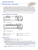
The IN1804 series models have different rear panel inputs and outputs as described below.
Figure 1 shows the IN1804 DI-DO model as an example, because it contains all input and
output connector types available on the IN1804 series.
• IN1804 standard — Inputs: Three HDMI and one DisplayPort. Outputs: Two HDMI.
• IN1804 DI — Inputs: Two HDMI, one DisplayPort, and one RJ-45 twisted pair (with IR
pass-through). Outputs: Two HDMI.
• IN1804 DO — Inputs: Three HDMI and one DisplayPort. Outputs: One HDMI and one
RJ-45 twisted pair (with IR pass-through).
• IN1804 DI-DO — Inputs: Two HDMI, one DisplayPort, and one RJ-45 twisted pair
(with IR pass-through). Outputs: Two HDMI and one RJ-45 twisted pair (with IR
pass-through).
21
1
100-240V ~ 1.3A MAX
50-60 Hz
LIN
R
LOUT
R
Tx Rx G
CT
2
CT
3
CT
4
CT
5
CT
6
CT
7
CT GV+
RS-232
RESET
LAN
34 1B
HDMI/CEC
OUTPUTS
REMOTE
AUDIO
CONTACT
/TALLY
INPUTS
Tx Rx G
IR
1A
OVER TP
Tx Rx G
IR
OVER TP
SIG
OUT
LINKSIG
IN
LINK
A
D
C
E
F
I
K
J
M
Q
L
N
B
O
P
G
H
Figure 1. Rear Panel Connectors, IN1804 DI-DO
Mounting and Cabling
Step 1 — Mount the device
a. Turn off or disconnect all equipment power.
b. Place the scaler on top of a flat surface using the provided rubber feet, mount it under a table using an optional kit for under
desk mounting, or attach it to a rack shelf using an optional rack shelf-mounting kit (kits are available at www.extron.com).
Step 2 — Connect inputs
Connect one or more of the following input sources as appropriate:
• Connect a DP source to the input 1 DisplayPort connector (see figure 1,
B
).
• Connect HDMI or DVI (with an appropriate adapter) video sources to HDMI input 2, input 3, and input 4 (available on IN1804
standard and DO models only) connectors (
C
). Securing the HDMI cables with provided LockIt brackets is recommended
(see the IN1804 Series User Guide for instructions).
• Connect a balanced or unbalanced audio source to the 5-pole captive screw AUDIO IN connector (
N
). See Audio Wiring on
page 3 for more information.
A
AC power connector
B
DisplayPort input connector
C
HDMI input connectors
D
Over TP IR pass-through
connector for input
E
TP RJ-45 input connector
F
TP RJ-45 output connector
G
Over TP IR pass-through
connector for output
H
HDMI output connector
I
LAN connector
J
Reset button
K
Reset LED
L
Remote RS-232 connector
M
Analog audio output
N
Analog audio input
O
+V port (for tally voltage output)
P
Ground pin (for contact ports)
Q
Contact/tally connectors
For information on safety guidelines, regulatory compliances, EMI/EMF compatibility, accessibility, and related topics, see the
Extron Safety and Regulatory Compliance Guide on the Extron website.

2
IN1804 • Setup Guide (Continued)
• IN1804 DI and DI-DO only: Connect a DTP2 transmitter or XTP matrix switcher to the twisted pair IN connector (
E
). For
cable wiring, see “Twisted Pair Recommendations for the IN and OUT TP Connectors,” below.
IN1804 DI and DI-DO only: To transmit or receive infrared data to and from a source connected to the DTP2 transmitter
or XTP matrix switcher, connect a control device (such as an Extron IPCP Pro Control Processor) to the 3-pole IR Over TP
captive screw port (
D
).
Step 3 — Connect outputs
a. Connect an HDMI output device (or DVI, with an appropriate adapter) to the rear panel HDMI output (
H
). For the IN1804
standard and DI models, two HDMI or DVI output devices can be connected. Secure the HDMI cables with the provided
LockIt brackets (see the IN1804 Series User Guide for instructions).
b. IN1804 DO and DI-DO only: Connect a DTP2, XTP matrix, or HDBaseT-compatible device to the twisted pair OUT
connector (
F
). For cable wiring and recommendations, see “Twisted Pair Recommendations.”
IN1804 DO and DI-DO only: To transmit or receive infrared data to and from a sink connected to the DTP2 receiver, XTP
matrix switcher, or HDBaseT receiver, connect a control device (such as an Extron IPCP Pro Control Processor) to the 3-pole
IR Over TP captive screw port (
G
).
c. Connect a balanced or unbalanced audio output device to the 5-pole captive screw AUDIO OUT connector (
M
). See Audio
Wiring on the next page for more information.
Step 4 — Connect control devices
a. To control the IN1804 device through Ethernet, connect a LAN to the RJ-45 LAN connector (
I
). The default IP address of
the scaler is 192.168.254.254, the default subnet mask is 255.255.255.0, and the default gateway address is 0.0.0.0.
b. For bidirectional RS-232 control, connect a host to the 3-pole captive screw connector (
L
). The baud rate is 9600.
c. For control through USB, connect a host device to the front panel USB mini-B port (see figure 2,
A
, on the next page).
Step 5 — (Optional) Connect contact closure and tally indicator devices
The CONTACT/TALLY panel contains seven 2-pole captive screw connectors, each with two pins labeled C and T (see figure 1,
Q
). Wire contact closure and tally devices to the connectors of each desired port as follows:
• Ports 1 through 4 (for input switching) — Each CONTACT/TALLY connector is labeled with the number of the video input
associated with it. Wire a push button or other contact closure switch to pin C (Contact) and to the shared pin G (Ground,
P
). If using a tally indicator, connect the shared +V pin (5 VDC, required for tally devices without a power supply,
O
) to the
T (Tally) pin. If using an SM Series Show Me
®
cable, see “Using an SM Series Show Me Cable,” below.
• Ports 5 through 7 (configurable via PCS) — Wire a push button or other contact closure switch to pin C (Contact) and to
the shared pin G (Ground,
P
). If using a tally indicator, connect the shared +V pin (5 VDC, required for tally devices without
a power supply,
O
) to the T (Tally) pin.
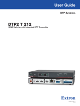
Using an SM Series Show Me cable:
The Contact and Tally connectors can also be used with Extron Show Me cables. The diagram
at right shows how to wire a Show Me cable to a contact input port (ports 1-4). For each Show
Me cable:
• Connect the red pigtail to the C pin corresponding to the input being used.
• Connect the black pigtail to the T pin of the same port.
Step 6 — Connect power
Connect a 100 to 240 VAC, 50-60 Hz power source to the AC power connector (
A
).
Twisted Pair Recommendations for the IN and OUT TP Connectors
Extron recommends using the following practices to achieve full transmission distances and
reduce transmission errors when connecting to a remote DTP2 endpoint, XTP matrix switcher, or HDBaseT receiver:
• Use Extron XTP DTP 24 SF/UTP cable for the best performance. At a minimum, Extron recommends 24 AWG, solid
conductor, STP cable with a minimum bandwidth of 400 MHz.
• Terminate cables with shielded connectors to the TIA/EIA-T568B standard (see the IN1804 Series User Guide for more
information).
• Limit the use of more than two pass-through points, which may include patch points, punch down connectors, couplers, and
power injectors. If these pass-through points are required, use shielded couplers and punch down connectors.
Black
Red
Show Me Cable
CT
1

3
ATTENTION:
• Do not connect these ports to a computer or telecommunications network.
• Ne connectez pas ces ports à des données informatiques ou à un réseau de télécommunications.
• DTP/DTP2 remote power is intended for indoor use only. No part of the network that uses DTP/DTP2 remote power
should be routed outdoors.
• L’alimentation DTP/DTP2 à distance est destiné à une utilisation en intérieur seulement. Aucune partie du réseau qui
utilise l’alimentation DTP/DTP2 à distance ne peut être routée en extérieur.
NOTE: When using shielded twisted pair cable in bundles or conduits, consider the following:
• Do not exceed 40% ll capacity in conduits.
• Do not comb the cable for the rst 20 meters, where cables are straightened, aligned, and secured in tight bundles.
• Loosely place cables and limit the use of tie wraps or hook-and-loop fasteners.
• Separate twisted pair cables from AC power cables.
RS-232 and IR Over TP Wiring
To transmit and receive IR signals between DTP2 endpoints, to an XTP matrix switcher, or to an HDBaseT receiver, connect a
control device to the Over TP IR 3-pole captive screw connector.
NOTE: RS-232 data can be inserted via Ethernet (see the IN1804 Series User Guide or the IN1804 PCS Help File for details).
Audio Wiring
Wire the audio input and output connectors as shown
at right. Use the supplied tie wrap to strap the audio
cable to the extended tail of the connector.
ATTENTION:
• For unbalanced outputs, do not connect wires
to the “-” poles.
• Pour les sorties asymétriques, ne connectez
pas de câbles aux pôles «-» .
NOTE: The length of exposed wires is important. The ideal length is 3/16 inch (5 mm).
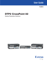
Front Panel Features
IN1804 DI/DO
SIGNAL
1
3
2
4
STATUS
MENU
ENTER
INPUT 1
INPUT 2
INPUT 3
INPUT 4
CONFIG
HDCP IN
HDCP OUT 1A
HDCP OUT 1B
AUTO SW
HOLD FOR 720p/1080p
A
CB D E F
Figure 2. Front Panel Features — All Models
A
USB configuration port — Connect a host device to this USB mini-B port for device configuration, control, file transfer, and
firmware upgrades.
B
Input selection buttons and LEDs (1-4) — Press one of these buttons to select an input. Each button has a green LED
that lights when the input is selected.
C
Signal (input) LEDs — For each input, these green LEDs light when an active video signal is detected.
D
Status LEDs — These green LEDs light to indicate the state of their corresponding settings:
• HDCP IN — Lights if the current input video signal is encrypted.
• HDCP OUT 1A and 1B — Light if the current output video signal is encrypted.
• AUTO SW — Lights if the unit is in an auto-switch mode.
Balanced Audio Output
Tip
Ring
Tip
Ring
Slee
ves
Unbalanced Audio Output
Tip
No Ground Here
No Ground Here
Tip
Sleeves
LR
LR
Unbalanced Audio InputBalanced Audio Input
Tip
Ring
Tip
Ring
Slee
ves
Tip
Sleeve
Sleeve
Tip
LR
LR
Do not tin the wires!
A
CONFIG port
B
Input buttons and LEDs
C
Signal LEDs
D
Status LEDs
E
MENU and ENTER buttons
F
Navigation buttons

4
68-3274-50 Rev. B
10 19
E
MENU and ENTER buttons — Press these buttons to access and navigate the on-screen display menu system.
F
Navigation buttons — Press these arrow buttons to navigate through the on-screen menu system or change settings.
Configuring the IN1804 Series
On-screen Display (OSD) Menu System
To congure IN1804 scalers using the OSD menu, connect a display device
and press the MENU button to open the OSD menu. The OSD menu consists
of eight submenus accessed using the front panel MENU or ENTER button.
Extron Product Configuration Software
To congure IN1804 scalers using PCS, install the software (available on
the Extron website, www.extron.com) to a PC connected to the scaler
via Ethernet or front panel USB Cong port. After the installation, start the
program. For full instructions, press <F1> on the keyboard or click the ?
button in the software and select Help File.
Basic SIS Commands
To congure IN1804 scalers with specic SIS commands via an
RS-232, USB, or Ethernet connection, use the Extron DataViewer utility
or a control system to send and receive SIS commands. The table
below lists a selection of SIS commands. For a full list of SIS commands and variables, see the IN1804 Series User Guide at
www.extron.com.
Command ASCII Command Response Additional Description
Select video input
X!! InX!
•
All] Select video and audio from input X!.
View current input
!
X!] View currently selected source X!.
Mute video (global)
1B
Vmt1]
Mute the video on all outputs.
Mute video and sync (global)
2B
Vmt2]
Mute the video and sync on all outputs.
Unmute video and sync (global)
0B
Vmt0]
Unmute the video and sync on all outputs.
NOTE: By default, video is unmuted after a power cycle.
Enable global output audio mute
1Z
Amt1]
Mute the audio on all outputs.
Disable global audio mute
0Z
Amt0]
Unmute the audio on all outputs.
Enable front panel lock mode 1
1X
Exe1]
Lock the entire front panel.
Enable front panel lock mode 2
2X
Exe2]
Lock the front panel except input switching, Auto-Image,
and output resolution reset (via down arrow button only).
Enable front panel lock mode 3
3X
Exe3]
Lock the front panel except input switching.
Disable front panel lock mode
0X
Exe0]
Allow all front panel adjustments and selections.
Set Auto-Switch mode
EX3) AUSW} AuswX3)] Select Auto-Switch mode X3).
View Auto-Switch mode
EAUSW} X3)]
View the current Auto-Switch mode.
Set user Auto-Switch priority
EPX3!
1
... X3!
4
AUSW} Ausw PX3!
1
... X3!
4
] Set priority X3! for auto-input switching. Lists inputs in
order of priority, from highest to lowest.
View user Auto-Switch priority
EP AUSW} X3!
1
... X3!
4
]
View user Auto-Switch priority. Lists inputs in order of
priority, from highest to lowest.
KEY:
X! = Input selection (1-4)
X3) = Auto-Switch mode: 0 = disabled (default), 1 = user defined priority, 2 = input memory priority (most recently detected input)
X3! = Input numbers for Auto-Switch priority: 1 = input 1, 2 = input 2, 3 = input 3, 4 = input 4
Firmware Updates
Download rmware updates from the Extron website and upload them via the internal web pages, PCS, or the Extron Firmware
Loader program.
© 2019 Extron Electronics All rights reserved. All trademarks mentioned are the property of their respective owners. www.extron.com
/