Page is loading ...

REVISION 21.3

Orolia Skydel User Manual
Table of Contents
1. Help
2. About This Manual
3. List of Acronyms
4. Overview
4.1. Power Level: Live Sky vs. Simulation
4.2. Data Flow
5. Hardware Selection
5.1. Software-Defined Radio
5.1.1. Accessories
5.1.1.1. Requirements for Ettus N310
5.1.1.1.1. 10 GbE Cable
5.1.1.2. Requirements for Ettus X300/X310
5.1.1.2.1. Daughterboards
5.1.1.2.2. 10 GbE Cable
5.1.1.3. Requirements for National Instruments USRP-294xR/USRP-295xR
5.1.1.4. Requirements for Dektec DTA-2115B
5.2. Reference Clock and PPS generator
5.2.1. Ettus X300/X310; National Instruments USRP-294xR/USRP-295xR
5.2.2. Ettus N310
5.2.3. Dektec DTA-2115B
5.2.3.1. Multiple Dektec DTA-2115B cards
5.3. RF Accessories
5.3.1. Attenuators
5.3.2. DC-Block
5.3.3. RF Signal Combiner
5.4. Computer
5.4.1. Minimal Computer Requirements
5.4.2. Recommended Computer
6. Hardware Setup
6.1. Ettus N310
6.1.1. Single Radio: 1 to 4 RF Outputs
6.2. Ettus X300/X310; National Instruments USRP-294xR/USRP-295xR
6.2.1. Single Radio: 1 or 2 RF Outputs
6.2.2. Dual Radio: 4 RF Outputs
6.2.3. Dual Radio - Multi-instance (RTK)
6.3. GPS Timing Receiver
6.3.1. OctoClock-G
6.3.2. Generic GPS Timing Receiver
6.4. Dektec DTA-2115B
6.4.1. Single Radio: 1 RF Output
6.4.2. Multiple Radios: Multiple RF Outputs
6.4.3. Multiple Radios - Multi-instance (RTK)
7. Software Setup
7.1. Firmware Programming
7.1.1. Ettus N310 Firmware (File system and FPGA image)
7.1.1.1. Programming Under Linux Ubuntu
7.1.2. Ettus X300/X310; NI USRP-294xR/295xR Firmware (FPGA image)
7.1.2.1. Programming Under Windows
7.1.2.2. Programming Under Linux Ubuntu
7.1.2.3. Unbricking Procedure

7.1.3. Ettus OctoClock and OctoClock-G Firmware
7.1.4. Computer BIOS
7.2. Software Configuration
7.2.1. Linux Ubuntu
7.2.1.1. General Parameters
7.2.1.2. Nvidia GPU Driver
7.2.1.2.1. Nvidia GPU Driver for Ubuntu 18.04/16.04 (Automatic)
7.2.1.2.2. Nvidia GPU Driver for Ubuntu 16.04 (Automatic)
7.2.1.3. Network Card Driver: 10 GbE Intel X520-DA2
7.2.1.4. Dektec DTA-2115B Driver
7.2.1.5. Orolia Skydel Installation
7.2.2. Microsoft Windows
7.2.2.1. General Parameters
7.2.2.2. Nvidia GPU Driver
7.2.2.3. Network Card Driver: 10 GbE Intel X520-DA2
7.2.2.4. Dektec DTA-2115B Driver
7.2.2.5. Orolia Skydel installation
7.2.2.6. Windows Firewall
7.2.3. Skydel-SDX Folder
8. Using Skydel
8.1. What is Skydel
8.2. Launching Skydel
8.2.1. Splash Screen
8.2.2. Welcome Screen
8.2.3. Main Window
8.2.4. Main Window Subtabs
8.2.5. Simulator State
8.2.6. Command Line Options
8.2.7. Launching Multiple Instances of Skydel
8.3. Licensing
8.3.1. USB Dongle
8.3.2. License Feature List
8.3.3. License Update
8.4. Preferences
8.4.1. General
8.4.2. Proxy
8.4.3. Synchronization
8.4.3.1. PPS OUT Delay
8.4.3.2. PPS IN Delay
8.4.3.3. Client / Server Settings
8.4.3.4. GPS Timing Receiver
8.4.3.4.1. Generic GPS Timing Receiver
8.4.3.4.2. Octoclock-G
8.4.4. USRP
8.4.5. Dektec
8.5. Configurations
8.5.1. Create New Configuration
8.5.2. Save Configuration
8.5.3. Open Configuration
8.5.4. Set as Default Configuration
8.5.5. Reset Default Configuration
8.6. Running Your First Simulation
8.6.1. Create a New Configuration
8.6.2. Add a radio
8.6.3. Select GNSS Signals
8.6.4. Select Vehicle Motion
8.6.5. Start the Simulation
8.7. Settings

8.7.1. Output
8.7.1.1. Radio Selection
8.7.1.2. Signal Selection
8.7.1.3. Reference Power Level
8.7.1.4. Optimizing Performance
8.7.1.5. IQ Data Files
8.7.1.6. Anechoic Chamber
8.7.1.7. Wavefront
8.7.1.7.1. Monitor
8.7.1.7.2. Signals Selection
8.7.1.7.3. Antenna
8.7.1.7.4. Phase Graph
8.7.2. Start Time
8.7.2.1. Custom Time
8.7.2.2. Current Computer Time
8.7.2.3. GPS Timing Receiver Time
8.7.2.4. Leap Seconds
8.7.2.5. Duration
8.7.3. Global
8.7.3.1. Atmosphere
8.7.3.1.1. Nominal
8.7.3.1.2. Errors
8.7.3.2. Earth Orientation Parameters
8.7.3.3. Logging
8.7.3.3.1. Raw
8.7.3.3.2. NMEA
8.7.3.3.3. Downlink
8.7.3.3.4. RINEX
8.7.3.3.5. HIL Input
8.7.3.4. Signal Level
8.7.3.5. Synchronize Simulators
8.7.3.6. Synchronize configuration between master and slaves
8.7.3.7. Synchronize Simulators with a GPS Timing receiver
8.7.4. GPS
8.7.4.1. General
8.7.4.2. Message Modification
8.7.4.2.1. LNAV
8.7.4.2.2. CNAV
8.7.4.2.3. MNAV
8.7.4.2.4. CNAV-2
8.7.4.3. Message Sequence
8.7.4.4. Pseudorange Offset
8.7.4.5. Orbits
8.7.4.5.1. Geostationary
8.7.4.6. Perturbations
8.7.4.7. Clock & Group Delay
8.7.4.8. Health
8.7.4.9. Multipath
8.7.4.10. Signal Enable/Disable
8.7.4.11. Transmitted PRN
8.7.4.12. Errors
8.7.4.13. Antenna
8.7.4.13.1. Models
8.7.4.13.2. Assignment
8.7.5. GLONASS
8.7.5.1. General
8.7.5.2. Leap Seconds
8.7.6. GALILEO

8.7.6.1. F/NAV Source Diversity
8.7.7. BEIDOU
8.7.8. QZSS
8.7.8.1. L1S augmentations
8.7.9. NavIC
8.7.10. SBAS
8.7.10.1. General
8.7.10.2. Message Sequence
8.7.10.3. Health
8.7.10.4. Ionospheric Masks
8.7.10.5. Ionospheric GIVEI
8.7.11. Vehicle
8.7.11.1. Body
8.7.11.1.1. Six Degrees of Freedom
8.7.11.1.2. Fixed
8.7.11.1.3. Circular
8.7.11.1.4. Track Playback
8.7.11.1.5. Vehicle Simulation
8.7.11.1.6. Hardware-In-the-Loop
8.7.11.1.7. Earth-Orbiting Spacecraft
8.7.11.2. Antenna
8.7.11.2.1. Models
8.7.11.2.2. Antenna Offset
8.7.11.2.3. Sequencer
8.7.11.3. Elevation Mask
8.7.12. Advanced Jammer
8.7.12.1. Simple dynamic transmitter tutorial
8.7.12.2. IQ-File Jammer
8.7.12.3. Multi-band Jammer
8.7.13. Advanced Spoofing
8.7.13.1. Spoofing instance
8.7.13.2. Truth instance
8.7.14. Plug-in
8.7.14.1. Plug-in Roles
8.8. Receiver
8.9. Map
8.10. Automate
8.10.1. Application Programming Interface (API)
8.10.1.1. Python
8.10.1.2. C++
8.10.1.3. C#
8.10.1.4. Vehicle Trajectory
8.10.1.4.1. Track
8.10.1.4.2. Route
8.10.1.5. Hardware-In-the-Loop (HIL)
8.10.1.6. Retrieve vehicle information
8.10.2. Skydel Script
8.11. Basic Interference
8.12. SNMP Support
9. Timing
9.1. Single Skydel Setup
9.1.1. Normal Start
9.1.2. Arm & Start
9.1.3. HIL Start
9.1.4. Sync With External PPS
9.2. Master/Slave Setup
9.2.1. Master/Slave Normal Start
9.2.2. Master/Slave Sync With PPS


1. Help
To request technical assistance, ask questions, or provide feedback on how to improve Skydel or this user
manual, please contact Orolia at [email protected]. To stay up to date on the latest Skydel news and
information, please visit our website: www.orolia.com↗ (https://www.orolia.com/).

2. About This Manual
The Orolia Skydel User Manual explains how to configure and use Skydel with different hardware setups and
operating systems. If you purchased a turnkey solution from Orolia or one of its Value-Added Resellers, you
were provided with additional documentation specific to your hardware setup.
This user manual is organized into 4 chapters:
Hardware Selection: This section describes the hardware required to run Skydel.
Hardware Setup: This section describes how to connect the hardware for different use cases.
Software Setup: This section explains how to install firmware, drivers, and Skydel.
Using Skydel: This section explains how to operate the Skydel software.

3. List of Acronyms
Acronym Description
BIOS Built In Operating System
BOM Bill Of Materials
CPU Central Processing Unit
CUDA Compute Unified Device Architecture
DAC Digital to Analog Converter
DUT Device Under Test
FPGA Field Programmable Array
FTP File Transfer Protocol
GNSS Global Navigation Satellite System
GPS Global Positioning System
GPSDO GPS Disciplined Oscillator
GPU Graphical Processing Unit
I/Q (IQ) Amplitude of In-Phase (I) and Quadrature (Q) of carrier
JTAG Joint Test Action Group
MIMO Multiple Input Multiple Output
MTU Maximum Transmission Unit
NI National Instruments
NMEA National Marine Electronics Association
OCXO Oven-Controlled Crystal Oscillator
PC Personnal Computer
PPS Pulse Per Second
RAM Random Access Memory
RF Radio Frequency
RTK Real-Time Kinematic
SDR Software Defined Radio
SFP (SFP+) Small Form-factor Pluggable
SMA SubMiniature version A
TX Transmission
TX/RX Transmission/Reception
UHD USRP Hardware Driver
USB Universal Serial Bus
USRP Universal Software Radio Peripheral
VCTCXO Voltage Controlled, Temperature Compensated Oscillator

4. Overview
To run your first successful simulation with Skydel, you don’t need to read this entire manual. You can start by
reading the Power Level: Live Sky vs. Simulation section followed by the Hardware Setup, and then jump
directly to Running Your First Simulation.
4.1. Power Level: Live Sky vs. Simulation
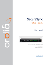
The main objective of a GNSS simulator is to create a RF signal identical to the “Live Sky” at the GNSS
receiver’s RF input connector. The next 2 diagrams depict the difference between the propagation of the real
signal and the simulated signal (using a USRP SDR as an example).
Propagation of the real GNSS signal from the satellite to the GNSS receiver
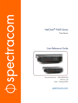
Propagation of the simulated GNSS signal from Skydel to the GNSS receiver
As you can see in the simulation case, the signal power level can be much higher at the output of the
SDR compared to the live sky. We strongly recommend that you:
1. use attenuators to avoid damaging your GNSS receiver;
2. use a DC-Block to avoid damaging the SDR due to the DC voltage provided by the GNSS receiver.
In general, when a GNSS receiver is receiving the RF signal from the live sky, the signal power level at the
antenna is -130 dBm. The antenna amplifies the RF signal power level to about -110 dBm at the GNSS
receiver’s input.
In the default simulation scenario, the GNSS simulator should create a signal with the same power level as the
GNSS receiver’s input. Depending on the SDR model used, a different attenuation level may need to be applied
to the signal emitted by the SDR.
4.2. Data Flow

1. Skydel, through a computer setup, generates real-time I/Q samples that represent the GNSS baseband
signals;
2. The I/Q samples are pushed over the transport link (Ethernet or USB);
3. The I/Q samples are queued in the SDR buffer. The SDR pulls the samples from the buffer at a steady rate
and converts them to RF;
4. When the SDR has more than one output, the signals are combined into a single RF cable;
5. The RF signal is attenuated before it is sent through a DC Block and reaches the GNSS receiver being
tested.

5. Hardware Selection
This section is intended for users who purchased a software-only version of Orolia’s Skydel. Users who own a
turnkey solution automatically receive a properly configured and very powerful computer workstation, a
Software-Defined Radio, and all required RF accessories.
There are 4 basic components to consider when building your simulator:
1. the Software-Defined Radio (SDR) model;
2. a Reference Clock and PPS generator (optional);
3. RF Accessories;
4. a computer.
If necessary, please contact [email protected] for a detailed BOM to build your own simulator.
5.1. Software-Defined Radio
The first item to select is the Software-Defined Radio. The selection of other components will ultimately depend
upon your choice of SDR.
The choice of an SDR model depends on your simulation requirements. Moreover, if you wish to repurpose
your SDR for other uses, you should consider other characteristics such as central frequency range, output
power level, community support, etc.
The SDR models currently supported by Skydel are as follows:
1. Ettus N310
2. Ettus X300/X310 or NI USRP-294xR/295XR
3. Dektec DAT-2115B
Here’s a quick chart comparing Skydel-supported SDR:
Ettus N310 Ettus X300/X310
NI USRP-294xR/295xR
Dektec DTA-2115B
Number of RF Outputs 4 2 1
Frequency Range 10 to 6000 MHz UBX: 10 to 6000 MHz 32 to 2186 MHz
Max Bandwidth per
Output
100 MHz 160 MHz 72 MHz
Reference Clock 10 MHz 10 MHz 10 MHz
PPS Synchro Yes Yes Yes
MIMO Operation Yes Yes Yes
DAC Resolution 14 bits 16 bits 14 bits
Data Link 10 GbE 10 GbE PCIe 1x 3.0

Ettus N310 Ettus X300/X310
NI USRP-294xR/295xR
Dektec DTA-2115B
Operating System Linux / Windows Linux / Windows Linux / Windows
The frequency range specified here is for the Ettus SDR with UBX daughterboard. Other RF
daughterboards have different frequency ranges. See the Ettus website for options and
specifications www.ettus.com/product-categories/rf-daughterboards↗
(https://www.ettus.com/product-categories/rf-daughterboards/).
Skydel limits the maximum bandwidth to provide 100% reliable streaming. SDR may be
capable of higher bandwidth for other applications.
5.1.1. Accessories
5.1.1.1. Requirements for Ettus N310
5.1.1.1.1. 10 GbE Cable
You will need to order a 10 GbE cable, as it’s not provided with the SDR. The cable should be SFP+ terminated
on both ends. See www.ettus.com/product/category/Cables↗ (https://www.ettus.com/product/category/Cables).
5.1.1.2. Requirements for Ettus X300/X310
5.1.1.2.1. Daughterboards
You will need to order 2 daughterboards for your SDR. Basically, the daughterboards contain the analog
components of the SDR. We strongly recommended using Ettus UBX-160 daughterboards, as they include an
RF shield and cover a larger range of frequencies. the Ettus website www.ettus.com/product-categories/rf-
daughterboards↗ (https://www.ettus.com/product-categories/rf-daughterboards/) for a complete list of daughterboards
from Ettus.
5.1.1.2.2. 10 GbE Cable
You will also need to order a 10 GbE cable, as it’s not provided with the SDR. The cable should be SFP+
terminated on both ends. See www.ettus.com/product/category/Cables↗
(https://www.ettus.com/product/category/Cables).
5.1.1.3. Requirements for National Instruments USRP-294xR/USRP-295xR
When ordering SDR from National Instruments, you will receive a device with integrated daughterboards. You
only need to order a 10 GbE cable, which is recommended and can be ordered from the National Instruments’
website.

5.1.1.4. Requirements for Dektec DTA-2115B
No extra accessories are required.
5.2. Reference Clock and PPS generator
In order to execute an accurate GNSS simulation, your SDR requires a precise reference clock. This section
review various timing options available depending on the SDR model in use. Note that if you require more than
one SDR in your simulation scenario (MIMO operation), each SDR will need to share the same 10 MHz
reference clock and have a common Pulse Per Second (PPS) signal in order to be synchronized.
Below is a list of external clocks that have been successfully tested with the various SDRs supported by Skydel.
Ettus OctoClock-G NI CDA-2990 Orolia CDM-5
Number of ports* 8 5
10 MHz Yes Yes
PPS Yes Yes
Form Factor External PCIe card
Manufacturer Website www.ettus.com/product/details/OctoClock-
G↗
(https://www.ettus.com/product/details/OctoClock-
G)
CDM-5 Product Page ↗
(https://www.orolia.com/products-
services/gnss-simulation/cdm-5)
The number of ports lists the available channels, thus the total number of concurrent SDR in MIMO
operation.
5.2.1. Ettus X300/X310; National Instruments USRP-294xR/USRP-295xR
Option 1 - External Reference Clock
You can use any 10 MHz reference clock with a precision of 200 ppb or better. Simply connect it to the REF
IN port of your SDR.
Option 2 - Internal GPSDO

You can add an internal 10 MHz reference clock inside the device itself. This add-on board is called the
GPSDO Kit and contains a 10 MHz OCXO reference oscillator. www.ettus.com/product/details/GPSDO-
MINI↗ (https://www.ettus.com/product/details/GPSDO-MINI)
NI USRP-295xR devices come out of the box equipped with a GPSDO. However, you must
consider option 3 for MIMO operations with this device.
Option 3 - External Clock with Multiple SDR
If your planned setup includes more than one SDR (MIMO operation), you will need an external reference
clock with multiple ports, such as this model.
5.2.2. Ettus N310
Option 1 - External Reference Clock
You can use any 10 MHz reference clock with a precision of 200 ppb or better. Simply connect it to the REF
IN port of your SDR.
Option 2 - Internal GPSDO
The Ettus N310 includes an internal GPSDO, which hosts a 10 MHz OCXO reference oscillator.
www.ettus.com/product/details/GPSDO-MINI↗ (https://www.ettus.com/product/details/GPSDO-MINI)
Option 3 - External Clock with Multiple SDR
If your planned setup includes more than one SDR (MIMO operation), you will need an external reference
clock with multiple ports, such as this model.
5.2.3. Dektec DTA-2115B
An external reference clock is required when using a single DTA-2115B card: the onboard reference clock is not
precise enough for GNSS simulation. Orolia’s CDM-5 is a PCIe card that fits alongside the DTA-2115B in a PC.
Consult the external reference clock table.
5.2.3.1. Multiple Dektec DTA-2115B cards
If your planned setup includes more than one SDR (MIMO operation), you will need an external reference clock
with multiple ports, such as this model.
5.3. RF Accessories
A handful of RF accessories are required in order to connect the SDR to your GNSS receiver (DUT). See
Hardware Setup for more information on how these accessories are connected.
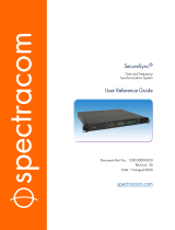
5.3.1. Attenuators

30 dB SMA Attenuator example from CrossRF
The RF signal power level output by the SDR is much stronger than the real live sky signal
would be when it reaches the GNSS receiver’s antenna. Consequently, Orolia strongly
recommends using attenuators between the SDR and the GNSS receiver to avoid damaging
your GNSS receiver.
Ettus N310 Ettus X300/X310
NI USRP-294xR/295xR
Dektec DTA-2115B
Attenuation Required 40 dB 60 dB 30 dB
5.3.2. DC-Block
SMA DC-Block example from Mini-Circuits
A DC-Block is a simple component that prevents the DC voltage from travelling back from the GNSS receiver to
the SDR. Typically, GNSS receivers will provide DC voltage (5 V to 12 V) to the antenna in order to power the
antenna’s amplifier. However, when using a simulator, this DC voltage is useless and could damage the SDR.
We strongly recommend using a DC-Block, even if your GNSS receiver can be configured to
stop providing DC at the antenna.
5.3.3. RF Signal Combiner

2:1 RF signal combiner example, from Mini-Circuits
When your simulation setup has more than 1 RF output, a RF signal combiner is required to combine the RF
signals into a single RF cable.
For a 2 RF outputs system, we recommend the ZAPD-2-272-S+ RF signal combiner from Mini-Circuits.
For a 4 RF outputs system, we recommend the ZN4PD-272+ RF signal combiner from Mini-Circuits.
5.4. Computer
While it is important to select a computer based on your GNSS simulation requirements, you may also want to
acquire a computer for uses that go beyond the scope of this manual.
5.4.1. Minimal Computer Requirements
The components listed in the following table are required to run a basic simulation: 12 satellites with only a
single GNSS signal each. While this kind of simulation scenario is enough to cover most use cases for most
users, the following section offers a future-proof list of recommended components.
Component Minimal Requirement
CPU Intel Core i5, 3rd generation
Minimal PassMark score of 7000 www.cpubenchmark.net↗
(https://www.cpubenchmark.net/)
RAM 8 GB DDR3
Storage 4 GB free space. We strongly recommend having at least 10% of free space on
the O/S drive.
GPU Nvidia GeForce, Quadro or Tesla
Minimum of 384 CUDA Cores
CUDA compute capability of 2.1
Network Card 1 GbE Intel PRO/1000 CT Desktop Gigabit
Typically, any onboard Intel, Realtek, or Broadcom card will be sufficient. Other
brands are not recommended.
Network Card 10 GbE Intel X520-DA2 E10G42BTDA
This is the only model supported by Skydel.
5.4.2. Recommended Computer

The following configuration is recommended for 4-constellation, dual frequency simulation. If you have
advanced simulation use cases such as RTK or multi-element antenna, please contact Orolia Canada support
for detailed information on an appropriate setup.
Component Recommended Manufacturer and Model
Motherboard ASUS Prime Z390-P
CPU Intel Core i7 9700K or better
RAM 16 GB DDR4
Storage Samsung 960 Evo NVMe PCIe M.2 250 GB
GPU Nvidia GeForce RTX 2080
Network Card 1 GbE Intel PRO/1000 CT Desktop Gigabit
Network Card 10 GbE Intel X520-DA2 E10G42BTDA

6. Hardware Setup
This section describes how to connect the different hardware components that compose the simulator. Different
scenarios are shown below, depending upon the SDR available and the simulation’s requirements. For details
on how to load FPGA firmware, see Firmware Programming.
6.1. Ettus N310
6.1.1. Single Radio: 1 to 4 RF Outputs
Starting from the computer (PC):
1. Connect the Orolia USB license dongle to any USB port of the computer.
2. Connect a 10 GbE cable (SFP+ terminated) between the computer’s Intel 10 GbE card (any port) and the
SDR’s port 1 (do not use port 0).
3. Optionally, connect an external 10 MHz reference clock to the EXT REF port of the N310.
4. Connect the N310 ports “RF 0/1/2/3, TX/RX” to the 4:1 RF combiner with shielded RF cables.
5. Connect the combiner to the 40 dB attenuators with a shielded RF cable.
6. Connect the 40 dB attenuators to a DC-Block.
7. Connect the DC-Block to the antenna port of the GNSS receiver.
6.2. Ettus X300/X310; National Instruments USRP-294xR/USRP-295xR
6.2.1. Single Radio: 1 or 2 RF Outputs

Starting from the computer (PC):
1. Connect the Orolia USB license dongle to any USB port of the computer.
2. Connect a 10 GbE cable (SFP+ terminated) between the computer’s Intel 10 GbE card (any port) and the
SDR’s port 1 (do not use port 0).
If your SDR does not have an internal GPSDO, connect an external 10 MHz reference clock to the EXT
REF port of the SDR.
3. Connect the SDR port “RF A, TX/RX” to the 2:1 RF combiner with a shielded RF cable.
4. Connect the SDR port “RF B, TX/RX” to the 2:1 RF combiner with a shielded RF cable.
5. Connect the combiner to the 60 dB attenuators with a shielded RF cable.
6. Connect the 60 dB attenuators to a DC-Block.
7. Connect the DC-Block to the antenna port of the GNSS receiver.
6.2.2. Dual Radio: 4 RF Outputs
/