Page is loading ...

SecureSync
2400 MODEL
Getting Started Guide
Document Part No.: 2400-5000-0051
Revision: 2
Date: 3-February-2021

© Orolia, 2021


Blank page.
iv SecureSync 2400 Getting Started Guide

CONTENTS
SecureSync 2400 Getting Started Guide • TABLE OF CONTENTS
v
About this Guide
iii
Product Overview
1
1.1 SecureSync Front Panel
1
1.1.1 Front Panel Keypad, and Display
1
1.1.1.1 Using the Keypad
2
1.1.1.2 Using the Front Panel Display
2
1.2 Unit Rear Panel
7
1.3 Interfaces
8
1.3.1 GNSS Receiver
8
1.3.2 10 MHz Output
8
1.3.3 Multi I/O
9
1.3.4 DCLS Output
10
1.3.4.1 1PPS Output
10
1.3.5 10/100/1000 Ethernet Port (RJ45)
11
1.3.6 10/100/1000 Ethernet Port (SFP)
11
1.3.7 RS-232 Serial Port (Rear Panel)
11
1.3.8 USB Serial Port (Front Panel)
11
1.3.9 Input Power
11
1.4 The SecureSync Web UI
12
1.4.1 The Web UI HOME Screen
12
Installation
15
2.1 Main Installation Steps
15
2.2 SAFETY
15
2.3 Unpacking and Inventory
17
2.4 Required Tools and Parts
18
2.4.1 Required GNSS Antenna Components
18
2.5 Mounting the Unit
18
2.5.1 Rack Mounting (Ears)
19
2.6 Connecting Network Cables
20
2.7 Connecting the GNSS Input
21


Product Overview
This section is designed to help you become familiar with the structure, features, and func-
tions of the SecureSync 2400.
1.1 SecureSync Front Panel
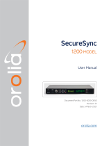
The front panel of a SecureSync unit consists of:
an LED time display
seven illuminated status LED menu buttons
a front panel control keypad
an OLED information display menu
micro-B USB serial console
intake for temperature-controlled cooling fans
The OLED information display is configurable using the front panel controls. The micro
USB serial interface and the front panel controls provide a means to configure the unit’s
network settings and perform other functions without requiring access to the Web UI.
SecureSync units with the SAASM GPS receiver option module installed also have an
encryption key fill connector and key zeroize pin switch on the left-hand side of the front
panel.
Figure 1-1: SecureSync front panel layout
1.1.1 Front Panel Keypad, and Display
To simplify operation and to allow local access to SecureSync, a keypad and an OLED
information display menu are provided on the front panel of the unit.
1.1 SecureSync Front Panel
SecureSync 2400 Getting Started Guide Rev. 2 1

The front panel keypad, information display menu, and status LED menu buttons can be
used to configure basic network settings and obtain status information. For more complex
functionality, users should refer to the Web UI or Command Line Interface (CLI).
1.1.1.1 Using the Keypad
The functions of the five keys are:
◀ ▶ ▲ ▼ arrow keys: Navigate to a menu option (will be highlighted); move the
focus on the screen; switch between submenus
▲ ▼ arrow keys: Scroll through parameter values in edit displays; move the focus
on the screen
✓ ENTER key: Select a menu option, or confirm a selection when editing
menu buttons: Press these buttons to navigate to each of
the seven main menus.
1.1.1.2 Using the Front Panel Display
There are seven main menu screens on the SecureSync front information display.
Figure 1-2: Status LED menu buttons
1.
Your front panel screen will timeout and darken after two minutes of inactivity. If
your screen is dark, press any menu or keypad button to wake.
2.
Press a menu button to enter that menu on the front panel display.
2
SecureSync 2400 Getting Started Guide Rev. 2
1.1 SecureSync Front Panel

3.
After entering a menu, the cursor will automatically begin on the submenu selection
that you last visited.
4.
Use the left and right buttons to switch between submenus if necessary.
5.
To enter into a submenu body, press the down button. You will only be able to high-
light fields that can be changed.
6.
If the field has arrows on either side of your selection, use the directional arrow keys;
OR:
7.
If the line is highlighted, press the ENTER button to change a value, and use the dir-
ectional keys to obtain the desired setting.
8.
Once your editing is done, press the ENTER button.
9.
Press ENTER again to confirm your choice in the confirmation menu that will appear
on the right side of the screen.
The main menu options and their functions are as follows:
Power Menu:
Management
halt the unit
reboot the unit
restore the factory defaults
Monitoring
view the temperature status: Board Temp, CPU Temp, and OSC (oscillator)
Temp
view the Fan(s) Speed
System
1.1 SecureSync Front Panel
SecureSync 2400 Getting Started Guide Rev. 2 3

view model number
view serial number
view software version
view licenses
view a rolling ribbon of option cards installed
GNSS Antenna Menu:
Constellations
view the status for GPS, GLONASS, BeiDou, Galileo, QNSS, and SBAS
turn reception OFF or ON to any satellite system by selecting the status
Settings
view or change receiver position mode
view or set position
view or change delay
Monitoring
view the following information:
antenna status
PPS validity
time validity
state
view for each satellite system:
chart of all visible satellites
4
SecureSync 2400 Getting Started Guide Rev. 2
1.1 SecureSync Front Panel

Inputs Menu:
Settings
view reference table
enable or disable references
Monitoring
view each input reference
view reference state, time, validity, and phase error
Time Menu:
Settings:
change the current time display
Monitoring:
view the oscillator type, disciplining state, and TFOM value
Outputs Menu:
Settings
1.1 SecureSync Front Panel
SecureSync 2400 Getting Started Guide Rev. 2 5

view list of outputs available
see outputs format
enable or disable outputs
Network Menu:
Settings: Scroll to each ETH connection to view information or perform actions:
enable or disable DHCP
view or set IP address
view or change gateway
view MAC address
Monitoring: View a graph for each ETH connection (highlight eth0 or eth1 and
toggle left and right)
Alerts Menu:
Status
show current major or minor alarms and descriptions
Monitoring
monitor memory usage
monitor CPU usage
monitor disk usage
Test
6
SecureSync 2400 Getting Started Guide Rev. 2
1.1 SecureSync Front Panel

confirm that the buttons on your front panel are working (highlight Press
VALID to start testing buttons and push the ✓ ENTER key).
1.2 Unit Rear Panel
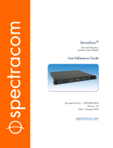
The SecureSync rear panel accommodates the connectors for all input and output ref-
erences.
GPS/GNSS antenna connector (SMA)
10 MHzoutput (BNC female connector)
Multi I/O (sub HD15 connector)
1PPS out, configurable DCLS Output (BNC female connector)
ETH0 1GB Ethernet (RJ45 connector)
ETH1 Ethernet (SFP connector)
Serial console (RJ45 connector)
Two or six slots for option cards
AC power input connection
Figure 1-3: Standard rear panel
1.2 Unit Rear Panel
SecureSync 2400 Getting Started Guide Rev. 2 7

Optional input/output connectors depend on the installed option cards.
Typically, option cards will be installed at the factory. Should you purchase an extra option
card at a later point, you will need to undergo field installation (for technically proficient ser-
vice personnel only).
1.3 Interfaces
The following specifications apply to the standard configuration of SecureSync. Inform-
ation on option card specifications can be found in the main user manual.
1.3.1 GNSS Receiver
Model: u-blox M8T
Compatible signals:
GPS L1 C/A Code transmissions at 1575.42 MHz
GLONASS L10F transmissions centered at 1602.0 MHz
Galileo E1 B/C transmissions at 1575.42 MHz
BeiDou B1 transmissions centered at 1561.098 MHz
QZSS L1-SAIF transmissions at 1575.42 MHz
Satellites tracked: Up to 72 simultaneously
Update rate: up to 2Hz (concurrent)
Acquisition time: Typically <27seconds from cold start
Antenna requirements: Active antenna module, +5V, powered by SecureSync, 16dB
gain minimum
Antenna connector: SMA (SMA to N-type conversion cable included in anxillary kit)
1.3.2 10 MHz Output
Signal: 10 MHz sine wave
Signal Level: +13 dBm ±2dB into 50 Ω
Harmonics: ˗40 dBc minimum
Spurious: ˗70 dBc minimum TCXO
Connector: BNC female
Accuracy rating depends on the oscillator selected during the ordering process.
8
SecureSync 2400 Getting Started Guide Rev. 2
1.3 Interfaces

1.3.3 Multi I/O
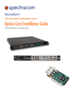
The Multi I/O HD15-pin connector can be configured to provide different signals.
Connector: 15 pin D-Sub (HD15) female
Available signals: RS232, (2) RS485, IRIG AM OUT, DCLS in, DCLS out
Possible Outputs: 1PPS, ASCII Time Code, IRIG (DCLS), IRIGAM, HAVEQUICK,
GPIO
Possible Inputs ("References"): 1PPS, ASCIITime Code, HAVEQUICK, IRIG(DCLS)
Pinout:
Figure 1-4: Multi I/O connector, viewed in mating direction on front of unit
Table 1-1:
Multi I/O connector signal pinout
Pin Signal
1 DCLS IN
2 GND
3 (First signal) RS485 A, non-inverting
4 (Second signal) RS485 A, non-inverting
5 RS232 TX OUT
6 DCLS OUT
7 GND
8 GND
9 GND
10 GND
1.3 Interfaces
SecureSync 2400 Getting Started Guide Rev. 2 9

Pin Signal
11 IRIG AM OUT
12 GND
13 (First signal) RS485 B, inverting
14 (Second signal) RS485 B, inverting
15 RS232 RX IN
Table 1-2:
Multi I/O signal defaults
Pins Channel Default Signal
6 & 7 DCLS OUT IRIG OUT
1 & 2 DCLS IN IRIGIN
15 & 10 RS232 IN ATC IN
5 & 10 RS232 OUT ATC OUT
3, 8, 13 RS485 (1) HAVEQUICK
OUT
4, 9, 14 RS485 (2) HAVEQUICKIN
11 & 12 IRIG AM OUT IRIGOUT(AM
ONLY)
1.3.4 DCLS Output
The rear panel DCLS OUT BNC female connector defaults to a 1PPS Output (see below),
but can be configured to produce different output signals: IRIG Output, HaveQuick Output,
and GPIOOutput.
1.3.4.1 1PPS Output
Signal: One pulse-per-second square wave (ext. reference connected to GNSS receiver)
Signal level: TTL compatible, 4.3 V minimum, base-to-peak into 50 Ω
Pulse width: Configurable pulse width (200 ms by default)
Pulse width range: 20 ns to 900 ms
Rise time: <10 ns
Accuracy: Positive edge within ±50 ns of UTC when locked to a valid, traceable input ref-
erence
Connector: BNC female
10
SecureSync 2400 Getting Started Guide Rev. 2
1.3 Interfaces

Table 1-3:
1PPS output accuracies
Oscillator Type
Accuracy to UTC
(1 sigma locked to GPS)
Holdover (constant temp. after 2weeks of GPS lock)
After 4 hours After 24 hours
Rubidium ±25 ns 0.2 μs 1μs
OCXO ±50 ns 1μs 25 μs
TCXO ±50 ns 12 μs 450 μs
1.3.5 10/100/1000 Ethernet Port (RJ45)
ETH0
Function: 10/100/1000 Base-T, auto-sensing LAN connection for NTP/SNTP and remote
management and configuration, monitoring, diagnostics and upgrade
Connector: RJ45, Network IEEE 802.3
1.3.6 10/100/1000 Ethernet Port (SFP)
ETH1
Function: 10/100/1000 (speed depends on connection) Base-T, auto-sensing LAN con-
nection for NTP/SNTP and remote management and configuration, monitoring, dia-
gnostics and upgrade
Connector: Ethernet via SFP
1.3.7 RS-232 Serial Port (Rear Panel)
Function: Accepts commands to locally configure the IP network parameters via CLI for ini-
tial unit configuration.
Connector: RJ45
Character structure: ASCII, 115200 baud, 1 start, 8 data, 1 stop, no parity
1.3.8 USB Serial Port (Front Panel)
Function: Accepts commands to locally configure the IP network parameters via CLI for ini-
tial unit configuration.
Connector: micro-B USB (requires installed driver; if your driver does not automatically
install, visit: https://www.ftdichip.com/Drivers/VCP.htm)
Character structure: ASCII, 115200 baud, 1 start, 8 data, 1 stop, no parity
1.3.9 Input Power
AC power source:
1.3 Interfaces
SecureSync 2400 Getting Started Guide Rev. 2 11

100 to 240 V
AC
, 50/60 Hz, ±10 %
Maximum power draw:
TCXO/OCXO oscillator installed: 40 W normal (50 W start-up)
Rubidium (Rb) oscillator installed: 50 W normal (80 W start-up)
Low-Phase Noise (LPN) Rubidium oscillator installed: 52 W normal (85 W start-up)
Backup Battery: SecureSync has an internal battery to support the Real Time Clock. The
battery is a small recharging lithium coin cell that is not customer-replaceable. This battery
will keep approximate time and date in a shutdown state over ~135 days before requiring
recharge. After full drain, the battery will require ~5 days to fully recharge. Minimum bat-
tery life is ~30+ years.
Hotswap Power Supply: Some SecureSync models have hot-swappable power supplies
and can ensure power redundancy in case of failure. Both power sleds have the same spe-
cifications as the standard AC Power Supply.
1.4 The SecureSync Web UI
SecureSync has an integrated web user interface (referred to as "WebUI" throughout this
documentation) that can be accessed from a computer over a network connection, using a
standard web browser. The WebUI is the most complete way to configure the unit, and for
status monitoring during everyday operation.
Note: If you prefer, an integrated Command-Line Interpreter interface
(CLI) allows the use of a subset of commands.
1.4.1 The Web UI HOME Screen
The HOME screen of the SecureSync web user interface ("Web UI") provides com-
prehensive status information at a glance, including:
vital system information
current status of the references
key performance/accuracy data
major log events.
The HOMEscreen can be accessed from anywhere in the Web UI, using the HOMEbutton
in the Primary Navigation Bar:
The Primary Navigation Bar provides access to all menus:
12
SecureSync 2400 Getting Started Guide Rev. 2
1.4 The SecureSync Web UI

HOME: Return to the HOME screen (see above)
INTERFACES: Access the configuration pages for …
… references (e.g., GNSS, NTP)
… outputs (e.g. 10 MHz, PPS, NTP) and
… installed input/output option cards.
MANAGEMENT: Access the NETWORK setup screens, and OTHER setup screens
e.g., to configure Reference Priorities, System Time, and the Oscillator.
TOOLS: Opens a drop-down menu for access to the system maintenance screens
and system logs.
HELP: Provides Spectracom Service Contact Information and high-level system con-
figurations you may be required to furnish when contacting Orolia Service.
1.4 The SecureSync Web UI
SecureSync 2400 Getting Started Guide Rev. 2 13

BLANK PAGE.
1.4 The SecureSync Web UI
14 SecureSync 2400 Getting Started Guide Rev. 2
/