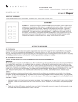
©Vantage, 8/11/2016 / IS-00698-B Station Bus Topology – Best Practices page 1 of 4
INSTALLATION
VANTAGECONTROLS.COM VANTAGE INSTALL GUIDES
2168 West Grove Parkway, Suite 300, Pleasant Grove, UT. 84062 USA
Telephone: 801 229-2800 ● Fax: 801 224-0355
Station Bus Topology — Best Practices
Overview
Vantage is committed to help dealers design projects that are robust and responsive, thus building confidence in customers and
dealers. Understanding station-bus best practices, is a critical part of a well designed system. This document shows multiple examples
and recommends 36V controllers for most installations. The examples have a common approach, that approach assumes station bus
runs in these examples are reaching design limits and wire length limits. There are times when a 24V controller with a single daisy chain
station bus run is acceptable. For example, using a 24V controller for a retrofit project or a RadioLink project is often acceptable.
However, keypad stations have greatly improved over the years and with the addition of so many 3-color LED buttons and LCD
touchscreens on the station bus, Vantage has updated the station voltage requirements in Design Center to ensure the station bus is
not overloaded and has sufficient “head-room” for proper 24-hour operation. This change in voltage requirements along with the best
practices for station bus designs presented in this document will help InFusion System installers start with a solid plan.
Station Bus Best Practices
1. Use IC-36 or IC-DIN with PSU36-DIN for most
projects. Plan for possible future expansions. A 36V
station bus provides greater power and performs
better on long station bus runs. Voltage drops over
the length of any station bus run, that is why a 36V
controller performs better than a 24V controller on
larger systems; voltage has a higher chance of being
at an acceptable level at the end of long runs.
1
2. The Infusion Controllers IC-36, IC-24, IC-DIN must be
earth grounded.
2
3. Use Vantage station bus wire sold in 1,000ft. rolls,
part number VDA-0143. or equivalent. Using smaller
gauge wire or non-qualified wire will reduce
system stability.
3
Vantage Station Bus Specification:
600V Insulation, 2C, 16AWG / 1.31mm2,
twisted, non-shielded, <30pF per foot.
4. Do not run station bus near any other parallel high or
low voltage wiring. Separate a minimum of 12" /
30.5cm from all other parallel wire runs. This limits
noise and interference on station bus and vice-versa,
limits noise and interference on other wire runs.
Unwanted noise on communication lines can cause
errors in communication.
4
Part #
VDA-0143

I N S T A L L A T I O N
©Vantage, 8/11/2016 / IS-00698-B Station Bus Topology – Best Practices page 2 of 4
5. The station count on a bus assumes an even
distribution of stations. Clustering a majority of the
stations near the end of a run will be problematic.
Possible solutions:
Relocate the controller or
Add another controller
.
5
6. Distribute stations along the entire station bus. This
requires proper location of Controllers.
No Station more than 1000 feet from a controller
Stations distributed along the entire station bus
No more than 2000 feet of cable per station bus
No station bus run longer than 1000 feet

I N S T A L L A T I O N
©Vantage, 8/11/2016 / IS-00698-B Station Bus Topology – Best Practices page 3 of 4
7. Design projects to balance stations on both station
bus runs. For example if a single controller is
configured with maximum stations and/or load
power, split the stations between each bus. Real
installations may not split evenly, but balancing the
stations on all station bus runs helps insure better
power and communication to all stations. Make sure
Design Center matches the actual station bus runs if
typing station serial numbers into the Design Center
project.
7
8. Daisy chain runs are fine on smaller systems, but use
multiple station bus runs and tie the runs together as
close to the controller as possible for larger systems.
For example, in a three story house run three,
separate station bus runs (one for each floor) and
have them tied together as near the controller as
possible for maximum voltage and communication at
each station connected to the controller.
8
9. Avoid “T” connections to add station bus to large
areas that are distant from the controller. For
example, in a three story home, do not use a “T”
connection to connect another floor that has
substantial area and a large number of keypads.
Remember, long station bus runs loaded with many
stations on the run reduces the voltage on the
station bus run. Voltage at the end of the run is
lower. Reduced voltage can cause station bus errors.
Use care to make sure each station bus run is not
over 1,000ft and that all runs connected to station
bus run 1 or 2 do not total more than 2,000ft.
Exception to this rule: If the system is small enough or
the “T” run is short and only adding one or two stations,
the “NO” wiring example at right is an acceptable
practice.
9

I N S T A L L A T I O N
©Vantage, 8/11/2016 / IS-00698-B Station Bus Topology – Best Practices page 4 of 4
10. Auxiliary ground connections should not be tied to
earth ground. Ground loops can disrupt station bus
communication and must be avoided.
Grounded Equipment:
If external equipment has earth ground and is
going to be connected to auxiliary connections
on keypad stations, CIS stations, CIS10-DIN
stations, or other stations, care must be taken to
make sure the contact input is isolated from earth
ground.
If the power plug looks like
this example – 3-prongs – the
equipment is usually earth
grounded.
Output Not Grounded Equipment:
Connected equipment that does not have an
earth ground on the output or is internally
isolated is usually okay.
Equipment Not Grounded:
If the power plug looks like
this example – 2-prongs –
the equipment is usually
not earth grounded.
*WARNING:
Do not defeat attached equipment’s earth ground
if present.
10
11. In Design Center individual station power
specification does not account for equipment
connected to the auxiliary connector. The auxiliary
connector provides 12V and is rated for 15mA. This
requires approximately 0.5W of power from the
station bus if fully loaded. This must be taken into
account manually. A good practice would be to know
the sensors power draw against the 15mA available
and to not exceed that.
11
12. The Contact Input Stations, CIS and CIS10-DIN
station’s 12V output is rated at 50mA. This requires
approximately 1.5W of power from the station bus if
fully loaded. This must be taken into account
manually.
12
13. Be mindful! Do not overload the combined 12V, 15mA
output on keypad auxiliary connections or the
combined 12V, 50mA output on Contact Input
Stations. Overloading these stations may result in
unreliable communications to this station. “Know”
the mA draw of connected motion sensors powered
from the auxiliary outputs. A good design guide is,
one motion sensor per keypad and three motion
sensors per CIS for 15mA sensors, or
two motion sensor per keypad and six motion
sensors per CIS for 6mA sensors.
14
-
 1
1
-
 2
2
-
 3
3
-
 4
4
Legrand VDA-0143-BOX Installation guide
- Type
- Installation guide
- This manual is also suitable for
Ask a question and I''ll find the answer in the document
Finding information in a document is now easier with AI
Related papers
-
Legrand Controller IC-DIN-II-LITE Installation guide
-
Legrand CIS10-DIN Installation guide
-
Legrand CIS10-DIN Installation guide
-
Legrand LCAP44H/HS Installation guide
-
Legrand LCAP32L Installation guide
-
Legrand Low-Voltage Output 0-10-PWM Station Installation guide
-
Legrand LCAP32M Installation guide
-
Legrand RF Enabler Installation guide
-
Legrand 9900837 User guide
-
Legrand EasyTouch II Wirelink ScenePoint Universal Dimmer and Keypad Station Installation guide
Other documents
-
 Vantage KS14XR-AWNA Installation guide
-
Nuvo P3500 Integration Manual
-
DAVIS Vantage Vue PRO+ Installation guide
-
Boston Whaler 320 Vantage Owner's manual
-
Siemens FC700A User manual
-
Boston Whaler 320 Vantage Owner's manual
-
Kollmorgen S72401 User manual
-
DAVIS Wireless Repeater (7627) Owner's manual
-
 Iteris VersiCam Installation and User Manual
-
 DMP Electronics XR500E SERIES Installation guide


