Page is loading ...


Technical User Guide 3
DA 75A 230 V AC
Product and Documentation Changes
SKOV A/S reserves the right to change this maual and the product described herein without further notice. In
case of doubt, please contact SKOV A/S.
Date of change appears from the front and the back page.
Note
• All rights reserved. No part of this manual may be reproduced in any manner whatsoever without
the express written permission from SKOV A/S.
• SKOV A/S has made all reasonable efforts to ensure the accuracy of the information contained in
this manual. Should any mistakes or imprecise information occur in spite of this, SKOV A/S would
appreciate being notified thereof
• Irrespective of the above, SKOV A/S shall not have any liability with respect to loss or damage
caused or alleged to be caused by reliance on any information contained herein
• Copyright 2016 by SKOV A/S.
Check the product as regards defects or damages (e.g. transport damages) prior to initial operation. In case of
defect or damage, please contact SKOV A/S or the nearest distributor.

4 Technical User Guide
DA 75A 230 V AC
1 Product Description................................................................................................. 5
2 Maintenance Instructions ........................................................................................ 5
2.1 Cleaning ............................................................................................................................... 5
3 Installation Guide ..................................................................................................... 6
4 Mounting Guide ....................................................................................................... 7
4.1 Placing ................................................................................................................................. 7
4.2 Winding of the winch motor ............................................................................................... 8
5 Trouble Shooting Instructions ...............................................................................10
5.1 Replacement of the circuit board ..................................................................................... 10
5.2 Replacement of the gear motor ........................................................................................ 11
5.3 Replacement of the switches ........................................................................................... 11
5.4 Emergency operation ....................................................................................................... 11
6 Technical Data ........................................................................................................12

Technical User Guide 5
DA 75A 230 V AC
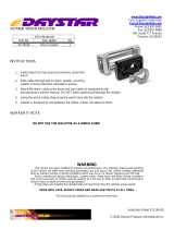
1 Product Description
DA 75A is a winch motor designed to control shutters and inlets, e.g. in livestock ventilation systems. DA 75A
has 2 wires which permit independent adjustment of pulling length and pulling direction. DA 75A is equipped
with a feedback potentiometer for position indication.
There is a switch to select between AUT and MAN (B). The winch motor is relay controlled and can be
infinitely variable controlled between open and closed position. In the automatic position the motor is
controlled by a climate computer. In the manual position the motor can be opened manually, stopped or closed
with the switch (C). DA 75A has built-in limit switches and a thermal contact to switch off the motor if it gets
too hot. Under emergency conditions DA 75A can be operated by means of a battery-operated drilling machine
and enclosed coupling piece (D) through the hole (A).
Figure 1
2 Maintenance Instructions
DA 75A requires no special maintenance. It should be checked regularly that the wires are O.K. and not worn
in the wire tracks.
2.1 Cleaning
IMPORTANT: Do not expose the winch motor to water or cleaning with a high-pressure cleaner. Likewise
the winch motor must be covered when a possible soaking function is active in the house.
A
E B C D

6 Technical User Guide
DA 75A 230 V AC
3 Installation Guide
The installation, service and troubleshooting in connection with electrical equipment must be
carried out by specialists in accordance with applicable national rules - in Europe in accordance
with EN 60204-1 and other applicable EU rules.
The installation of a supply isolator is required for each motor and power supply, so
maintenance of electrical equipment can be carried out in a dead environment. Supply isolator is
not supplied by SKOV A/S.
If automatic operation is required, the switch (B) should be set to AUT.
DA 75A is supplied with 230 V ac on the wires 3 (= phase) and 4 (= neutral). The motor will open if wire 1 is
supplied with 230 V ac and close if wire 2 is supplied with 230 V ac. Wire 5 is safety ground.
The potentiometer is supplied with e.g. 10 V dc, positive on wire 6 and negative on wire 8. Wire 7 will then be
loaded with 0 Volt in closed position, 5 Volt in half-opened and approx. 10 Volt in completely opened position.
In case of power failure it is possible to operate the motor by means of the enclosed coupling and a drilling
machine, preferably battery operated.
DA 75A is connected to the automatic unit by 2 cables (Figure 2): A five-core cable with earth and a three-core
cable. The five-core cable includes earth, neutral, fixed phase (for manual operation), open and close, see under
Function. The three-core cable includes positive, signal voltage and negative. The potentiometer cannot stand
230 V!
After the installation set the switch (B) to MAN, and run the motor from stop to stop via the switch (C) in order
to make sure that the mechanical hook-up is O.K. Set the switch (B) to AUT and check that the motor is able to
open, stop and close via the automatic unit. The opening and closing directions are labelled on the wire wheel.
Figure 2
Open
Close
Fixed Phase P
Neutra N
Earth

Technical User Guide 7
DA 75A 230 V AC
4 Mounting Guide
DA 75A is delivered with 2 wires discs and corresponding wire. If only one wire is to be used, dismount the
uttermost. In order to use the same bolts again, mount the wire discs again.
If 3 wires should be used, an extra wire disc with wire, item No. 432925, can be re-mounted. The same bolts
can be used.
DA 75A should be mounted vertically. In countries with a hot climate it should be avoided that the sun shines
directly on DA 75A. 3 or 4 pcs. of 10 mm through-bolts should be used to secure the unit. Above the unit, (A)
on Figure 1, sufficient space should be left free for an emergency opening crank or a battery-operated drilling
machine to operate the motor, should emergency opening be required. The wires can be led in any direction,
also through the wall.
4.1 Placing
Be aware that other objects do not make any obstacle for the wire when placing the winch motors in the house,
e.g. pipes, feed pipes, doors, windows, rafters and light fittings. The winch motor must be placed suitable on
grounds of manual operation, service and emergency operation.
Figure 3: Placing of the winch motor
(Emergency
operation)

8 Technical User Guide
DA 75A 230 V AC
4.2 Winding of the winch motor
The wires should be wound on to the wire wheel in order to obtain the correct pulling or slacking length.
Figure 4
When you are going to wind a winch motor, it should always be in the fully closed position. Figure 4 shows
where to measure to get rough values in the scheme. Please note that min. 3 mm should be free to the outer
periphery and the hub should always be “covered” by a wire winding as shown in the figure. The figure also
shows the definition of “number of wire windings = 1”.
Following table shows the rough relation between load, the number of wire windings and the pulling or
slacking lengths.
1000 N equal 98 kg.
DA 75-1
Measure to
periphery
before
pull/sla
One-way pull
Balanced
No. of wire
windings
Pulling
length [mm]
Slacking
length [mm]
Tractive
force [N]
Moment
[Nm]
Tractive
force [N]
Moment
[Nm]
1
237
-
48
1794
56
2384
75
2
260
232
45
1748
60
2170
75
3
284
256
42
1702
64
1992
75
4
307
279
39
1656
68
1840
75
5
331
303
36
1610
71
1710
75
6
354
326
33
1564
74
1597
75
7
377
349
30
1498
75
1498
75
8
401
373
27
1411
75
1411
75
9
424
396
24
1379
75
1333
75
10
447
419
21
1333
75
1263
75
11
471
443
17
1263
75
1201
75
12
494
466
14
1201
75
1144
75
13
517
489
11
1144
75
1092
75
14
541
-
8
1092
75
1045
75
min.3 mm
min. winding

Technical User Guide 9
DA 75A 230 V AC
DA 75-3
Measure to
periphery
before
pull/sla
One-way pull
Balanced
No. of wire
windings
Pulling
length [mm]
Slacking
length [mm]
Tractive
force [N]
Moment
[Nm]
Tractive
force [N]
Moment
[Nm]
1
502
-
48
1767
59
2251
75
2
549
-
45
1721
63
2059
75
3
596
484
42
1674
66
1898
75
4
642
530
39
1628
69
1760
75
5
689
577
36
1582
72
1640
75
6
736
624
33
1536
75
1536
75
7
783
670
30
1445
75
1445
75
8
829
717
27
1379
75
1363
75
9
876
764
24
1363
75
1290
75
10
923
811
21
1290
75
1225
75
11
969
857
17
1225
75
1166
75
12
1016
904
14
1166
75
1112
75
13
1063
951
11
1112
75
1064
75
14
-
-
8
1064
75
1019
75
DA 75-6
Measure to
periphery
before
pull/sla
One-way pull
Balanced
No. of wire
windings
Pulling
length [mm]
Slacking
length [mm]
Tractive
force [N]
Moment
[Nm]
Tractive
force [N]
Moment
[Nm]
1
1117
-
48
1711
64
2025
75
2
1210
-
45
1665
67
1868
75
3
1303
-
42
1619
70
1735
75
4
1397
-
39
1573
73
1618
75
5
1490
-
36
1517
75
1517
75
6
1584
1135
33
1427
75
1427
75
7
1677
1229
30
1379
75
1348
75
8
1771
1322
27
1348
75
1277
75
9
1864
1416
24
1277
75
1213
75
10
1958
1509
21
1213
75
1155
75
11
2051
1603
17
1155
75
1102
75
12
-
1696
14
1102
75
1054
75
13
-
1789
11
1054
75
1010
75
14
-
-
8
1010
75
970
75

10 Technical User Guide
DA 75A 230 V AC
DA 75-12
Measure to
periphery
before
pull/sla
One-way pull
Balanced
No. of wire
windings
Pulling
length [mm]
Slacking
length [mm]
Tractive
force [N]
Moment
[Nm]
Tractive
force [kg]
Moment
[Nm]
1
2810
-
48
-
64
182
75
2
3025
-
45
-
67
170
75
3
3245
-
42
-
70
160
75
4
3460
-
39
-
73
150
75
10
-
2815
21
-
75
112
75
11
-
3020
17
-
75
107
75
12
-
3250
14
-
75
103
75
13
-
3480
11
-
75
99
75
5 Trouble Shooting Instructions
If the motor will not run, set the switch (B) to MAN and try to operate the motor via switch (C). If successful,
check the opening and closing connections to the automatic unit and the potentiometer, if necessary. If not
successful, check that 230 V ac is being supplied. If so, set switch (C) to open position (upwards), remove the
cover and measure the voltage between open (E) and neutral (N) on terminal J1 (Figure 5). If the voltage is
O.K. and the motor does not run, replace the gear motor or the motor capacitor (H). If the voltage is not O.K.,
replace the circuit board. If the opening limit switch (O on Figure 5) is activated, set switch (C) to close
position (downwards) and measure the voltage between close (G) and neutral (N) on terminal J1. If the external
motor temperature exceeds 110°C, a thermal cut-out (T) is activated and the motor cannot run.
Figure 5
5.1 Replacement of the circuit board
Mark the wires connected to opening, closing and to the potentiometer. Remove the plug, unscrew and remove
the wires of J1 and J4. Loosen the 3 bolts by means of the enclosed Allen key and pull out the circuit board.
Adjust the potentiometer shaft (P) on the new circuit board to fit into the hole of the large gear-wheel. Remount
the circuit board. If the motor is in a position where it is being activated by the limit switch, it is necessary to
help the arms of the limit switch contacts (O) and (S) on to the cam of the gear-wheel. The thermal cut-out (T)

Technical User Guide 11
DA 75A 230 V AC
is fastened to the motor by the enclosed cable ties. Tighten the bolts and remount wires and plug. Test the
motor as mentioned under Installation.
5.2 Replacement of the gear motor
Relieve the wires and loosen the screw (E) on Figure 1. Now the complete wire wheel can be removed from the
shaft. Take care that the wires do not come off the wire tracks. Remove the circuit board, see above. Remove
the 4 bolts, by which the gear is secured to the console, by means of the long Allen key. Mount the new gear
motor in reverse order. Prior to remounting the wire wheel, set the key-way of the shaft to its previous position
(as to DA 75A-3 the shaft should also be adjusted to the correct turn, compare with the plastic gear wheels on
the opposite side). Test the motor as mentioned under Installation.
5.3 Replacement of the switches
A spare unit includes 2 switches and a set of wires. Remove the relief fitting in the cover, pull out the wires of
the switches and press the switches out of the cover by squeezing the barbs together. Mount the new switches,
please do not forget that the 3-position switch should be placed to the right (front view). Connect the wires, see
Figure 6 which is also depicted on the inside of the cover. Test the motor as mentioned under Installation.
Figure 6
5.4 Emergency operation
In case of a total breakdown the system can be operated manually. Unscrew the bung at the top of the winch
motor (A on Figure 1). Mount the enclosed coupling (D) on a drilling machine, preferably battery operated.
Lead in the coupling through the hole at (A) until it engages with the motor shaft. If the shaft is turned
clockwise, the gear motor opens the system. Do not open or close too much as the mechanical installation may
be damaged.
344114
DA 75 - 230V
1
2
3
4
5
Aut.
Man.
0

12 Technical User Guide
DA 75A 230 V AC
6 Technical Data
DA 75A-1
DA 75A-3
DA 75A-6
DA 75A-12
Item No
432032
432033
432034
432063
Motor data
230
230
230
230
Power consumption
0.36
0.36
0.36
0.36
Max. continuous running time
30
30
30
30
Max. torque
75
75
75
75
No. of wire wheel turns
0,8
2.4
4,8
9,8
Running time between end stop
2.5 – 3.5
2.5 – 3.5
5 -7
10 - 13
No. of wire tracks and width
5
5
5
5
Wire
4
4
4
4
Wire length
10
10
10
10
Min. wire length and force
25 /1771
53 /1743
116 /1688
280 /1850
Max. wire length and force
55 /1026
107 /1053
203 /1110
346 /1520
Shipping weight
16.2
17
16.8
16.9
Shipping dimensions
415x315x175 mm
Protection class*
IP 54
Condensator
7 F
Potentiometer
10 kΩ
Potentiometer position closed
0-2 % af max.
Potentiometer position open
90-95 % af max.
* It is assumed that the base is plan, i.e. ≤ 1.5 mm difference of height and that the screws of the cover are tightened with
min. 200 Ncm.

Technical User Guide 13
DA 75A 230 V AC

Technical User Guide 14
DA 75A 230 V AC


/