Page is loading ...

Spray Height Controller
UC4+ SERVICE MANUAL 2012

Printed in Canada
Copyright 2012 by NORAC Systems International Inc.
Reorder P/N: UC4+ SERVICE MANUAL 2012 Rev B
NOTICE: NORAC Systems International Inc. reserves the right to improve products and their specifications without notice and
without the requirement to update products sold previously. Every effort has been made to ensure the accuracy of the information
contained in this manual. The technical information in this manual was reviewed at the time of approval for publication.

Contents
1 GETTING STARTED ................................................................................................. 1
1.1 Safety Precautions ................................................................................................................................ 1
1.2 Related Documents ............................................................................................................................. 2
1.3 How to Use This Manual .................................................................................................................... 2
1.4 Initial Troubleshooting ........................................................................................................................ 3
2 SYMPTOMS ................................................................................................................. 4
2.1 General Operation ............................................................................................................................... 4
2.2 Operational Messages.......................................................................................................................... 6
2.3 Hydraulics ............................................................................................................................................... 8
2.4 Performance ........................................................................................................................................10
2.5 Automatic Setup or Retune Problems...........................................................................................12
3 TEST PROCEDURES ............................................................................................... 16
3.1 Height Sensor Test ............................................................................................................................16
3.2 Roll Sensor Test .................................................................................................................................19
3.3 Temperature Sensor Test ................................................................................................................26
3.4 Power Supply Test .............................................................................................................................27
3.5 Communication Test .........................................................................................................................28
3.6 Boom Functions Test ........................................................................................................................35
3.7 Manual Valve Override Test ............................................................................................................38
3.8 Valve Driver Test ...............................................................................................................................40
3.9 Switch Inputs Test ..............................................................................................................................42
3.10 Boom Speed Test ...............................................................................................................................43
3.11 Checking Mechanical Components ................................................................................................44
3.12 Checking Settings ...............................................................................................................................48
4 REFERENCE .............................................................................................................. 52
4.1 Menu Structure Map .........................................................................................................................52
4.2 Automatic System Setup ...................................................................................................................53
4.3 Retune ...................................................................................................................................................56
4.4 Height Sensor Mounting ...................................................................................................................57
4.5 Roll Sensor Mounting (Passive Roll) ...............................................................................................59
4.6 Roll Sensor Mounting (Enhanced Stability) ...................................................................................63
4.7 Roll Sensor Mounting (Active Roll™) ...........................................................................................64
4.8 Replacing Components .....................................................................................................................66
4.9 Height Sensor Setup ..........................................................................................................................70
4.10 Roll Sensor Setup (Passive Roll) ......................................................................................................72
4.11 Roll Sensor Setup (Enhanced Stability) ..........................................................................................74
4.12 Roll Sensor Setup (Active Roll™) ..................................................................................................75

4.13 Output Channel (Valve) Setup ........................................................................................................76
4.14 Boom Geometry Calibration ...........................................................................................................78
4.15 Updating the Firmware .....................................................................................................................78
4.16 Sprayer Types ......................................................................................................................................79
4.17 Maintenance .........................................................................................................................................80
5 WARRANTY & SUPPORT INFORMATION ........................................................ 81
5.1 Technical Support ...............................................................................................................................81
5.2 Registering Your Product .................................................................................................................81
5.3 Statement of Limited Warranty ......................................................................................................82

1
1 Getting Started
1.1 Safety Precautions
The UC4+™ Spray Height Control system will greatly improve your spraying height accuracy
and protect the boom against damage in a wide variety of field conditions. However, under
some circumstances performance may be limited. The operator of the sprayer must remain
alert at all times and override the automatic control when necessary.
Under no circumstances should any service work be performed on the machinery
while the UC4+™ Spray Height Control system is in Automatic Mode.
Always ensure that the UC4+™ Spray Height Control system is powered down or
in Manual Mode:
• Before leaving the operator’s seat.
• When transporting the machine.
Before working on any part of the booms:
• Set the UC4+™ system to Manual Mode.
• Turn the sprayer engine off.
Do not operate this system before:
• Reading and understanding the operator’s manual.
• Thoroughly understanding the machine operation.

2
1.2 Related Documents
The following documents should be used for reference in addition to this service manual.
• UC4+™ Operator Manual
• UC4+™ Cable Guide
• UC4+™ Installation Manual (for your sprayer type)
• UC4+™ End User Installation Manual (for your sprayer type, if applicable)
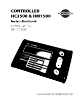
1.3 How to Use This Manual
This manual is designed to assist technicians with troubleshooting the UC4+™ Height Control
System. To use this guide follow these steps:
1. Gather some initial information (Section 1.4).
2. Identify the symptom (Section 2).
3. Follow the list of actions under the symptom until you have found and solved the
problem.
Figure 1: Troubleshooting Flowchart

3
1.4 Initial Troubleshooting
Before troubleshooting the problem, gather some basic information about the problem and the
sprayer.
• What is the sprayer make and model?
• Are there additional options: Active Roll™, Severe Terrain, Enhanced Stability or
Proportional Main Lift?
• Customer information: name and location.
• What is the firmware version and serial number of the UC4+ Control Panel?
• Is this a new installation?
• Are there any error messages?
• What is the perceived problem? Can you recreate the problem? Is it intermittent?
• Has anything changed since the system was working? Have any settings changed or has
an Automatic Setup or Retune been attempted?

4
2 Symptoms
2.1 General Operation
The system will not go into automatic mode.
Possible Cause
Action
Section
The Automatic System Setup has not
been completed.
If you have not completed an Automatic
Setup then complete it now.
4.2
The Height Sensors are out of range. Lower the booms to normal working
height.
N/A
Poor Height Sensor readings. Test the Height Sensors. 3.1
The system will not go into manual when the sprayer switches are pressed.
Possible Cause
Action
Section
Input wires may be damaged or not
installed correctly.
Test the switch inputs. 3.9
The system resets when a valve is turned on.
Possible Cause
Action
Section
Poor power or ground connection. Check the power supply. 3.4
The system will not power up.
Possible Cause
Action
Section
Poor power or ground connection. Check the power supply. 3.4

5
The system intermittently goes into manual mode.
Possible Cause
Action
Section
The Height Sensors are reading “NR”. Test the Height Sensors. 3.1
The interface cable may be damaged or
not installed correctly.
Ensure the interface cable is installed
correctly and not damaged. Refer to
your installation manual.
N/A
There may be noise on the sprayer’s
electrical system.
Ensure the interface cable is not routed
near the sprayer’s valve coils.
N/A
Add a power line filter or freewheeling
diodes on one or more of the sprayer’s
solenoid valves.
N/A

6
2.2 Operational Messages
“NC” (No Communication)
Possible Cause
Action
Section
Failed sensor or CANbus. Test the communication. 3.5
“NR” or “NoRdg” (No Reading)
Possible Cause
Action
Section
Height Sensor is reporting “NR”. It is normal to see this message
occasionally for Height Sensors. If you
are seeing this message all the time the
Height Sensor may be having difficulty
obtaining a proper reading.
Test the Height Sensors.
3.1
“Minimum Override”
Possible Cause
Action
Section
This message is displayed when the
target height is lower than the Minimum
Height Mode allows.
Raise the target height. N/A

7
“Disabled”
Possible Cause
Action
Section
Access to the system setup features
(Automatic Install, ReTune) has been
disabled by the installer to avoid
unintentional system changes.
If you need to access the setup features
that have been disabled, contact your
NORAC dealer.
N/A
“>>>>>>>>>>”
Possible Cause
Action
Section
The control panel is busy with a task
that may take a few seconds.
Wait for the arrows to disappear before
activating any control panel switches.
N/A
“Absent”
Possible Cause
Action
Section
This message is typically shown on
startup if one or more of the sensors
are not communicating on the CANbus.
Test the communication. 3.5

8
2.3 Hydraulics
The boom will not raise or lower.
Possible Cause
Action
Section
The hydraulics or electrical outputs are
not functioning or are not installed
correctly.
Perform the Boom Function Test. 3.6
The boom will raise when it should lower, or vice versa.
Possible Cause
Action
Section
The raise and lower lines to the tilt
cylinders may be reversed.
Ensure the raise lines are connected to
the “B” ports and the lower lines are
connected to the “A” ports.
N/A
Perform the Boom Function Test. 3.6
The hydraulic oil is overheating.
Possible Cause
Action
Section
Using the UC4+™ system at higher
sensitivities may create a greater
demand on the sprayer’s hydraulics.
Try lowering the sensitivity. N/A
The hydraulic system may require an
open center valve block.
An open center valve block option is
available from Norac which may reduce
heating on certain hydraulic systems.
Contact your NORAC dealer for more
details.
N/A

9
The boom will creep up or down in Manual Mode.
Possible Cause
Action
Section
The raise and lower lines to the tilt
cylinders may be reversed.
Ensure the raise lines are connected to
the “B” ports and the lower lines are
connected to the “A” ports.
N/A
There may be an internal problem with
the NORAC valve block. Some possible
causes are; a sticky valve, worn valve,
faulty check valves or a foreign object
stuck in the valve block.
If possible try removing any foreign
objects in the valve. The valve block
may also need to be repaired or
replaced.
N/A
This may be caused by a problem with
the sprayer’s hydraulic system.
Check the sprayer hydraulics. Check if
the tilt cylinders are leaking and replace
the seals if needed.
N/A

10
2.4 Performance
The boom is unstable, erratic or sluggish in Automatic Mode.
Possible Cause
Action
Section
Automatic System Setup has not been
completed.
If you have not completed an Automatic
Setup then complete it now.
4.2
Incorrect settings. Check the settings. 3.12
Poor Height Sensor readings. Test the Height Sensors. 3.1
Poor Roll Sensor readings. Test the Roll Sensors. 3.2
Failed Temperature Sensor. Test the Temperature Sensor. 3.3
There may be a problem with the
mechanics of the sprayer.
Check the sprayer mechanical
components.
3.11
Failed sensor or CANbus. Test the communication. 3.5
Incorrect Roll Sensor mounting. Check the Roll Sensor mounting as
shown in the installation manual for
your kit.
4.5
Incorrect Height Sensor mounting. Check the Height Sensor mounting as
shown in the installation manual for
your kit.
4.4
The system may not be driving a boom
function, or driving the wrong boom
function.
Perform the Boom Function Test. 3.6
Low or inconsistent boom speeds. Test the boom speeds. 3.10

11
The boom does not appear to be level in Automatic Mode.
Possible Cause
Action
Section
The sensitivity setting may be too low. Check the sensor height readings from
the run screen, if it differs from the
target height then try turning up the
sensitivity. The default tolerance for a
sensitivity setting of 5 is ± 6 cm (2.5
inches).
N/A
The Deadzone setting may be calibrated
incorrectly.
Check the Deadzone settings. 3.12.1
The sensor offset heights may be
incorrect.
Test the Height Sensors. 3.1
The boom moves all the way to the top in Crop Mode.
Possible Cause
Action
Section
The sensors may be reading off of the
boom in Crop Mode.
Ensure the sensors are aligned and
mounted correctly.
4.4
Poor Height Sensor readings. Test the Height Sensors. 3.1

12
2.5 Automatic Setup or Retune Problems
When performing an Automatic Setup or Retune:
• The sprayer must be over level bare dirt or gravel. Do not perform the auto setup
over vegetation, concrete, water or snow.
• The hydraulic system should be under a normal load and at a normal working
temperature. The oil should be warm and the sprayer’s engine should be normal
working RPM. Start the solution pump if possible.
For Retune problems only, follow Section 2.5.5 below.
2.5.1 Starting the Automatic Setup
Ensure you have selected the correct sprayer type. Refer to Section 4.16 for a list of sprayer
types.
A list of connected sensors will be displayed. Ensure the list matches the sensors included in
your system.
Automatic Setup does not show all the correct sensors are connected.
Possible Cause
Action
Section
Failed sensor or CANbus. Test the communication. 3.5
2.5.2 Switch Test
When you press the sprayer’s switches during the switch test, the system will check for voltage
on the corresponding input line. It will show “OK” for each correct switch press. If it sees a
voltage on another input line it will let you know there is an error.
The system does not detect a switch press or indicates there is an error.
Possible Cause
Action
Section
The interface cable may not be correctly
installed.
Check the inputs. 3.9
Note: Not all sprayer types will perform the Switch Test.

13
2.5.3 Sensor Detect
During this test the system will set the sensors height at 35 inches (90 cm) and then move the
booms to determine which sensors are located where on the sprayer.
The left or right wing does not move during the sensor detect test.
Possible Cause
Action
Section
The hydraulics are not functioning or
not installed correctly.
Perform a boom function test.
3.6
The electrical outputs to the valves are
not functioning or are installed
incorrectly.
The left and right wings move up but the sensor detect test does not finish or gives
an error.
Possible Cause
Action
Section
Poor Height Sensor readings. Test the Height Sensors. 3.1
The left and right wings will move down
after the sensor detect test. If the test
times out or stalls after the right wing
moves up, then the down functions may
not be functioning correctly.
Perform a boom function test. 3.6

14
2.5.4 Boom Geometry Calibration
When calibrating the boom geometry, push the boom down approximately 2 – 3 feet (50 – 100
cm) and then let go of the boom. Do not push the boom tip into the ground when performing
this test.
Note: Not all sprayer types will perform the Boom Geometry Calibration.
The boom geometry calibration fails, does not finish or finishes before the boom is
pushed.
Possible Cause
Action
Section
Incorrect Roll Sensor mounting. Check the Roll Sensor mounting as
shown in the installation manual for
your kit.
4.5
Poor Height Sensor readings. Test the Height Sensors. 3.1
Poor Roll Sensor readings. Test the Roll Sensors. 3.2
The boom may not be pivoting freely. Check the sprayer mechanical
components.
3.11

15
2.5.5 Hydraulic Calibration
The hydraulic calibration “times out” or gives an error.
Possible Cause
Action
Section
Poor calibration target. Ensure you are performing the
calibration over bare level gravel or soil.
N/A
If the system “hangs up” during the
Automatic Setup, release the “Auto”
switch and move the booms to normal
working height and/or move the sprayer
forward or backward a little. Press and
hold the “Auto” switch to resume.
N/A
Poor Height Sensor readings. Test the Height Sensors. 3.1
Poor Height Sensor mounting. Check the Height Sensor mounting. 4.4
Poor Roll Sensor readings. Test the Roll Sensors. 3.2
Poor Roll Sensor mounting. Check the Roll Sensor mounting. 4.5
Excessively windy conditions. If you are trying to calibrate in
excessively windy conditions, the boom
may always be moving due to the wind
and the system will not be able to
calibrate correctly. Calibrate the system
in less windy conditions.
N/A
Problem with the sprayer mechanics. Check the sprayer mechanics. 3.11
The sensors went out of range during
the calibration.
If the system “hangs up” during the
Automatic Setup, release the “Auto”
switch and move the booms to normal
working height. Press and hold the
“Auto” switch to resume.
N/A
The boom was not set close to 35” (90
cm) during the Sensor Detect.
Restart the Automatic Setup and ensure
the boom is at 35” (90 cm) for the
Sensor Detect.
N/A

16
3 Test Procedures
3.1 Height Sensor Test
Before testing the Height Sensors, perform a visual check of the sensors to look for any
physical damage or improper mounting. Refer to Section 4.4 for proper Height Sensor
mounting.
1. Ensure the system has previously completed an Automatic Setup. If the system has not
passed the Sensor Detect portion of the Automatic Setup then the sensors may not be
configured to the correct locations.
2. Perform this test over level bare soil or gravel. The system must be in Manual and Soil
mode.
3. Level the booms and adjust the main lift to 10 inches (25 cm) above the ground or to
the bottom of the stroke.
4. Press “Sensor Display” to navigate to the “Left Outer” height reading screen.
5. Check the height reading of the “Left Outer” Height Sensor while raising the left boom
manually up to 80 inches (200 cm).
6. You should see a continuous and accurate height reading from 10 inches (25 cm) to 80
inches (200 cm).
7. Repeat steps 2 to 6 for each of the Height Sensors.
8. Repeat steps 2 to 7 in Crop Mode.
Refer to the following sections for troubleshooting if you experience any of the following
errors:
Error message: “NR” Page 17
Error message: “NC” Page 18
Inaccurate or erratic height reading Page 18
/