Page is loading ...

Hardi OEM
End-User Installation Manual
Spray Height Controller
Improving the competitiveness of Industry and
Agriculture through Precision Measurement

Printed in Canada
Copyright © 2005-08 by NORAC Systems International Inc.
Reorder P/N: UC4+BC+HD3-INSTE Rev B (Hardi OEM)
NOTICE
NORAC Systems International Inc. reserves the right to improve products and their specifications without notice and without the requirement to update
products sold previously. Every effort has been made to ensure the accuracy of the information contained in this manual. The technical information in
this manual was reviewed at the time of approval for publication.

1
1 INTRODUCTION
Congratulations on your purchase of the NORAC UC4+ Spray Height Controller. This system is
manufactured with top quality components and is engineered using the latest technology to provide
operating features and reliability unmatched for years to come.
When properly used the system can provide protection from sprayer boom damage, improve sprayer
efficiency, and ensure chemicals are applied correctly.
Please take the time to read this manual completely before attempting to install the system. A thorough
understanding of this manual will ensure that you receive the maximum benefit from the system.
YOUR INPUT CAN HELP MAKE US BETTER! If you find issues or have suggestions regarding
the parts list or the installation procedure, please don’t hesitate to contact us via the information
given below:
Phone: 1-800-667-3921 Canada (Toll Free)
1-866-306-6722 United States (Toll Free)
0-800-404-8389 United Kingdom (Toll Free)
1-306-664-6711 all other regions
Website: www.norac.ca
2 PARTS LISTS
The parts that come with your UC4+ Sprayer Boom System are listed below. The item number on the left
side of this table references each part.
Table Item Part Number Name Quantity
C10* 44650-35 CABLE POWER GENERIC PULL-TYPE 1
E01* 4461BC+HD UC4 PLUS BOOM CONTROL PANEL HARDI 1
M01 446BC+MAN7 OPERATOR MANUAL UC4+ SPRAY HEIGHT CONTROL 1
M13* UC4+BC+HD3-INSTE MANUAL INSTALLATION END-USER HARDI 1

2
ROP
3 INSTALLATION
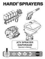
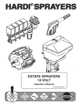
1. Install the UC4+ Control Panel (E01) in the
cab of the sprayer. Mount the panel where it
will be clearly visible and within easy reach
of the operator.
A good spot to mount the UC4+ control
panel is on the right hand side of the cab to
the Roll Over Protection Bar (ROP). Four
pilot holes for the screws provided need to be
drilled to facilitate the control panel
mounting.
Another option is to purchase an adapter for
the flexible panel mount that has a 3/8" NC
threaded stud on the end to bolt through an
existing mount. You can find these at your
local outdoor store as a RAM mount part
number RAM-B-236. (See
http://www.ram-mount.com/)
Figure 1 – Control Panel Mounting
ROP

3
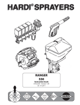
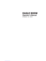
Figure 2 – Cable Configurations: C10 and C11
2. Connect the power cable (C10) to the UC4+
Control Panel in the sprayer cab. Ensure that
both plugs (P16A and P4) are connected to
the panel (Figure 2).
Ensure that the UC4+ Control Panel is
OFF for the remaining installation
(Bottom of switch pressed IN). Use
caution when handling the 12V power
line of the sprayer wiring.
3. Connect the 3-pin AMP connector (P3) on
the C10 cable to an auxiliary power
connection inside the sprayer cab. If an
appropriate connector(s) cannot be found it
may be necessary to cut off the connector(s)
and splice into the existing wiring.
4. Route the free end (R16) of C10 to the
exterior of the cab, to the vicinity of the
tractor hitch. This connector will provide
your hitch connection. Route the cable
accordingly and connect it to P16 on the
sprayer. The procedure for the installation of
the UC4+ system is now complete.
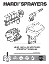
5. For optimal performance of the UC4 system,
there should be very little play at the hitch
clevis. The addition of polymer washers can
help tighten up this connection (Figure 3).
Figure 3 – Hitch Point
6. Power on the UC4+ panel, if “HD3” shows
up as your sprayer type, you can start the
ReTune process as per the UC4+ Operator
Manual. This will tune the UC4+ hydraulic
parameters to your tractor hydraulic system.
7. If no type is selected yet, start the Install as
per the UC4+ Operator Manual.

Canada
NORAC Systems International Inc.
CALL TOLL FREE: 1-800-667-3921
(306)664-6711
SHIPPING ADDRESS:
3702 Kinnear Place
Saskatoon, SK
S7P 0A6
United States
Norac, Inc.
CALL TOLL FREE: 1-866-306-6722
(763)786-3080
SHIPPING ADDRESS:
1290 Osborne Rd NE, Suite F
Fridley, MN
55432-2892
www.norac.ca
/