Page is loading ...

RANGER
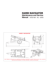
550
Instruction book
67022203 - Version 1.00
US - 01.2011


RANGER
550
Instruction book
67022203 - Version 1.00
US - 01.2011
HARDI® reserves the right to make changes in design, material, or specification without notice thereof.
HARDI® and other product names are registered trademarks of HARDI® Inc. in the U.S. and in other countries.


TOC.1
Table of contents
1 - Welcome
Welcome letter ......................................................................................................................................1
2 - Safety notes
Operator safety .....................................................................................................................................1
General info ............................................................................................................................................................................................................... 1
Local poison information center ...........................................................................................................2
3 - Description
General info ...........................................................................................................................................1
View ................................................................................................................................................................................................................................ 1
View ................................................................................................................................................................................................................................ 2
Identification plates .............................................................................................................................................................................................. 2
Roadworthiness ...................................................................................................................................................................................................... 2
Sprayer use ................................................................................................................................................................................................................. 3
Frame ............................................................................................................................................................................................................................. 3
Tank ................................................................................................................................................................................................................................ 3
Liquid system ........................................................................................................................................4
General info - valve system .............................................................................................................................................................................. 4
Pump ............................................................................................................................................................................................................................. 4
Valves and symbols ............................................................................................................................................................................................... 4
Suction valve = Blue symbols ......................................................................................................................................................................... 4
Agitation & Tank rinse valves = White symbols .................................................................................................................................. 4
Diagram - Centrifugal Liquid system ......................................................................................................................................................... 5
Control unit ................................................................................................................................................................................................................ 5
Filters .............................................................................................................................................................................................................................. 5
HARDI® FILLER .......................................................................................................................................................................................................... 5
Boom .....................................................................................................................................................6
Boom and terminology ...................................................................................................................................................................................... 6
Equipment .............................................................................................................................................7
Steps ............................................................................................................................................................................................................................... 7
Platform ........................................................................................................................................................................................................................ 7
Tank level indicator ............................................................................................................................................................................................... 7
Remote system pressure gauge ................................................................................................................................................................... 8

TOC.2
Table of contents
4 - Sprayer setup
General info ...........................................................................................................................................1
Unloading the sprayer from the truck ...................................................................................................................................................... 1
Before putting the sprayer into operation ............................................................................................................................................. 1
Support jack .............................................................................................................................................................................................................. 1
Mechanical connections ........................................................................................................................2
Hitch - Height adjustment ................................................................................................................................................................................ 2
Transmission shaft - Operator’s safety ...................................................................................................................................................... 2
Transmission shaft - Installation .................................................................................................................................................................... 2
Hydraulic systems .................................................................................................................................4
General info ............................................................................................................................................................................................................... 4
Requirements - tractor (SPB-HY) ................................................................................................................................................................... 4
Requirements - tractor (SPB-HV) ................................................................................................................................................................... 4
Requirements - tractor (SPB-HZ) ................................................................................................................................................................... 4
Requirements - Ace 206 Hydraulic pump .............................................................................................................................................. 4
Open center hydraulics (optional equipment) ................................................................................................................................... 5
Electrical connections ............................................................................................................................6
Power supply ............................................................................................................................................................................................................ 6
Control boxes ........................................................................................................................................................................................................... 6
Installation of control unit brackets ............................................................................................................................................................ 6
Installation of control box - EVC control unit ........................................................................................................................................ 6
Road safety kit .......................................................................................................................................................................................................... 7
Track width, axles and wheels ...............................................................................................................8
Altering the track width ..................................................................................................................................................................................... 8
Turning rim and rim plate ................................................................................................................................................................................. 8
5 - Operation
Boom .....................................................................................................................................................1
Safety info ................................................................................................................................................................................................................... 1
Maneuvering of the boom - HY version .................................................................................................................................................. 1
Maneuvering of the boom - HV version .................................................................................................................................................. 2
Maneuvering of the boom - HZ version .................................................................................................................................................. 3
Liquid system ........................................................................................................................................4
Filling of water ......................................................................................................................................................................................................... 4
Filling through tank lid ....................................................................................................................................................................................... 4
Filling of main tank using Quick Fill (optional) .................................................................................................................................... 4
Filling of clean water tank ................................................................................................................................................................................. 5
Adjustment of EVC operating unit .............................................................................................................................................................. 5
Safety precautions - crop protection chemicals ................................................................................................................................. 6
Filling chemicals through tank lid ............................................................................................................................................................... 6
Filling Liquid chemicals by HARDI® FILLER ............................................................................................................................................. 7
Filling Powder chemicals by HARDI® FILLER ......................................................................................................................................... 8
Agitation before re-starting spraying ........................................................................................................................................................ 9
Operating the control unit while spraying ............................................................................................................................................ 9
Quick reference - Operation ......................................................................................................................................................................... 10
Cleaning ...............................................................................................................................................11
General info ............................................................................................................................................................................................................ 11
Cleaning the tank and liquid system ...................................................................................................................................................... 12
Cleaning and maintenance of filters ....................................................................................................................................................... 12
Use of flush tank and rinsing nozzles ..................................................................................................................................................... 13
Quick reference - Cleaning ............................................................................................................................................................................ 14
Technical residue ................................................................................................................................................................................................ 14
Using the drain valve ........................................................................................................................................................................................ 14
Spray Technique - see separate book. ................................................................................................................................................... 14
Optional extras - see separate books. ..................................................................................................................................................... 14

TOC.3
Table of contents
6 - Maintenance
Lubrication ............................................................................................................................................1
General info ............................................................................................................................................................................................................... 1
Recommended lubricants ................................................................................................................................................................................ 1
Boom lubrication & oiling plan ...................................................................................................................................................................... 1
Trailer lubrication & oiling plan ..................................................................................................................................................................... 2
Service and Maintenance intervals .......................................................................................................3
10 hours service - In-Line filter (optional equipment) ..................................................................................................................... 3
10 hours service - Spraying circuit ............................................................................................................................................................... 3
50 hours service - Transmission shaft ........................................................................................................................................................ 3
50 hours service - Wheel bolts and nuts ................................................................................................................................................. 3
50 hours service - Tire pressure ..................................................................................................................................................................... 3
250 hours service - Readjustment of the boom ................................................................................................................................. 3
250 hours service - Hydraulic circuit .......................................................................................................................................................... 4
250 hours service - Hoses and tubes ......................................................................................................................................................... 4
250 hours service - Wheel bearings ............................................................................................................................................................ 4
1000 hours service - Transmission shaft .................................................................................................................................................. 4
1000 hours service - Wheel bearings ......................................................................................................................................................... 5
Occasional maintenance ........................................................................................................................6
General info ............................................................................................................................................................................................................... 6
Cone check/replacement for pressure regulator ...............................................................................................................................6
Cone check/replacement for EVC distribution valve ....................................................................................................................... 6
Drain valve seal replacement ......................................................................................................................................................................... 6
Nozzle tubes and fittings .................................................................................................................................................................................. 7
Adjustment of 3-way-valve .............................................................................................................................................................................. 7
Readjustment boom - general info ............................................................................................................................................................ 7
Alignment of center and inner wing sections ..................................................................................................................................... 8
Alignment of inner and outer wing sections ....................................................................................................................................... 8
Adjusting the front fold cable ........................................................................................................................................................................ 9
Breakaway section adjustment ..................................................................................................................................................................... 9
Check/adjust sprocket timing ..................................................................................................................................................................... 10
Adjusting boom level to ground .............................................................................................................................................................. 10
Adjusting rear cable .......................................................................................................................................................................................... 11
Adjusting center section cables ................................................................................................................................................................. 11
Shock absorbers ................................................................................................................................................................................................... 11
Wear bushing replacement on boom lift ............................................................................................................................................ 12
Change of tire ........................................................................................................................................................................................................ 13
Change of bulbs .................................................................................................................................................................................................. 13
Shield replacement on transmission shaft .......................................................................................................................................... 14
Replacement of transmission shaft cross journals. ........................................................................................................................ 14
Off-season storage ..............................................................................................................................15
Off-season storage program ........................................................................................................................................................................ 15
Preparing the sprayer for use after storage ........................................................................................................................................ 15
7 - Fault finding
Operational problems ...........................................................................................................................1
General info ............................................................................................................................................................................................................... 1
Liquid system ............................................................................................................................................................................................................ 2
Hydraulic system - HY model. ........................................................................................................................................................................ 3
Hydraulic system - HV/HZ model. ................................................................................................................................................................ 3
Mechanical problems ............................................................................................................................4
Mechanical problems .......................................................................................................................................................................................... 4
Emergency operation - Liquid system ...................................................................................................................................................... 4

TOC.4
Table of contents
8 - Technical specifications
Dimensions ............................................................................................................................................1
Overall dimensions ............................................................................................................................................................................................... 1
Tank capacities ...................................................................................................................................................................................................... 1
Weight .......................................................................................................................................................................................................................... 1
Wheel and axle dimensions ........................................................................................................................................................................... 1
Specifications ........................................................................................................................................2
Pump model ACE 206 hydraulic ................................................................................................................................................................... 2
Pump model ACE 150 PTO drive .................................................................................................................................................................. 2
Filters and nozzles ................................................................................................................................................................................................. 2
Temperature and pressure ranges .............................................................................................................................................................. 2
Tire pressure ............................................................................................................................................................................................................. 2
Materials and recycling .........................................................................................................................3
Disposal of the sprayer ....................................................................................................................................................................................... 3
Electrical connections ............................................................................................................................4
Electrical connections for SPRAY II .............................................................................................................................................................. 4
Electrical connections for hydraulic control box ................................................................................................................................ 5
EVC .................................................................................................................................................................................................................................. 6
Hydraulic box ............................................................................................................................................................................................................ 6
Plug positions for HV/HZ hydraulics .......................................................................................................................................................... 8
Road traffic lights .................................................................................................................................................................................................... 8
Charts ....................................................................................................................................................9
Boom hydraulics - HZ .......................................................................................................................................................................................... 9
Boom hydraulics - HV .......................................................................................................................................................................................... 9
Boom hydraulics - HY ....................................................................................................................................................................................... 10
9 - Warranty
Warranty policy and conditions ............................................................................................................1

1.1
1 - Welcome
Welcome letter
Dear New HARDI® Owner,
Thank you for purchasing your new HARDI® product and welcome to the ever-increasing family of proud HARDI® owners.
HARDI® is the leading sprayer company in offering growers strong, reliable products made for the widest range of
applications worldwide. Quality, reliability, and resale value make the HARDI® product line the preferred product line of
customers both in North America as well as worldwide. Our guiding principle is to provide the highest level of customer
satisfaction and long term value in the marketplace today. We have developed a very high level of customer loyalty in the
marketplace which we are very proud of and strive every day to maintain and to continue to grow.
HARDI® is your specialist in spraying and we spend all of our time and keep all of our focus on spraying. We do not share our
resources between other types of products or compromise on anything in providing the best quality sprayers to the market
today. We can provide the latest in technology with our products if desired, or allow them to operate with the technology
that you already use on other products in most cases. You get to decide that, and what best suits your needs. We feel that
you, our customer, are the best suited to answer that question for your operation. Either way, you decide, and we will try and
help make it happen for you.
Our broad spectrum of product offerings, from the ruggedly simple models we build to our highly sophisticated models,
the built-in HARDI® strength and reliability ensures a low cost of ownership. HARDI® sprayers are all based on a functional
design concept of being as simple to operate as possible and to meet our customers’ requirements for all their application
needs.
Please take the time to thoroughly read the Operator’s Manual before using your equipment. You will find many helpful hints
as well as important safety and operation information.
Some of the features on your HARDI® sprayer were suggested by growers. There is no substitute for “on farm” experience
and we invite your comments and suggestions. If any portion of this instruction book remains unclear after reading it,
contact your HARDI® dealer or service personnel for further explanation before using the equipment.
For Product, Service or Warranty Information please contact your local HARDI® dealer.
- Please use the HARDI® Customer Service number: 1-866-770-7063
- Or send your email to CUSTSERV@hardi-us.com
HARDI® NORTH AMERICA INC.
Visit us online at: www.hardi-us.com
1500 West 76th St.
Davenport, Iowa 52806
Phone: (563) 386-1730
Fax: (563) 386-1280
Sincerely,
Wayne Buchberger
President

1 - Welcome
1.2

2 - Safety notes
2.1
2 - Safety notes
Operator safety
€This symbol means DANGER. Be very alert as your safety is involved!
±This symbol means WARNING. Be alert as your safety can be involved!
This symbol means ATTENTION. This guides to better, easier and safer operation of your sprayer!
General info
Note the following recommended precautions and safe operating practices.
€Read and understand this instruction book before using the equipment. It is equally important that other operators
of this equipment read and understand this book.
€Local law may demand that the operator is certified to use spray equipment. Adhere to the law.
€Wear protective clothing.
€Rinse and wash equipment after use and before servicing.
€Never service or repair the equipment while it is operating.
€Always replace all safety devices or shields immediately after servicing.
€Do not eat, drink or smoke while spraying or working with contaminated equipment.
€Wash and change clothes after spraying.
Wash tools if they have become contaminated.
€In case of poisoning, immediately seek medical advice. Remember to identify chemicals used.
€Keep children away from the equipment.
€If any portion of this instruction book remains unclear after reading it, contact your HARDI® dealer for further
explanation before using the equipment.
€Be careful not to hit people or surroundings when maneuvering the sprayer, especially when backing.
€Slow down when driving in uneven terrain, as the machine might be in risk of turning over.
€Pressure test with clean water prior to filling with chemicals.
€Disconnect electrical power before servicing and depressurize equipment after use and before servicing.
€Do not attempt to enter the tank.
€Do not go under any part of the sprayer unless it is secured. The boom is secure when placed in the transport
brackets.
€If an arc welder is used on the equipment or anything connected to the equipment, disconnect power leads before
welding. Remove all inflammable or explosive material from the area.

2 - Safety notes
2.2
Local poison information center
€If you live anywhere in the United States, the following toll free number will connect you to your Local Poison
Information Center.
PHONE NO. 1 - 800 - 222 - 1222
€If you live outside the United States, find the number for the poison control center in your phone book and write it
in the space below:
PHONE NO._______ - _______ - __________
€Keep a list, in the space provided below, of all the chemicals that you have in use.
1. _______________________________________________________________________________________________
2. _______________________________________________________________________________________________
3. _______________________________________________________________________________________________
4. _______________________________________________________________________________________________
5. _______________________________________________________________________________________________
6. _______________________________________________________________________________________________
7. _______________________________________________________________________________________________
8. _______________________________________________________________________________________________
9. _______________________________________________________________________________________________
10. ______________________________________________________________________________________________

3 - Description
3.1
3 - Description
General info
View
1.Main tank lid
2. Tank level indicator
3. Platform
4.Suction valve
5.Hitch
6. Support jack
7. Step
8.Pump (hydraulic pump location)
9.Pressure regulator
10. HARDI® FILLER valve (optional)
11.HARDI® FILLER (optional)
12. Quick Fill (optional)
13. Flush tank (optional)
14.Clean water tank
15.Remote system pressure gauge
16. Agitation valve
17. Tank rinse valve (optional)

3 - Description
3.2
View
Identification plates
An identification plate fitted on the frame indicates year (YY) and
identification number (XXXXXX) of machine.
Frame, boom center frame and other main steel components have
identification plates indicating type and part number. (not illustrated)
Roadworthiness
When driving on public roads and other areas where the highway code applies, or areas where there are special rules and
regulations for marking and lights on implements, you should observe these and equip implements accordingly.
ATTENTION! Max. driving speed is 20 mph (32 km/h). Be aware that this may differ due to local law. Contact local
authorities for information of max. driving speeds.
18.System pressure gauge
19.Distribution valves
20. Hydraulic block
21.Step
22. Pump (PTO driven pump location)
23. Main tank

3 - Description
3.3
Sprayer use
The HARDI® sprayer is for the application of crop protection chemicals and liquid fertilizers. The equipment must only be
used for this purpose. It is not allowable to use the sprayer for other purposes. If no local law demands that the operator
must be certified to use spray equipment, it is strongly recommended to be trained in correct plant protection and in safe
handling of plant protection chemicals to avoid unnecessary risk for persons and the environment when doing your spray
job.
Frame
Very strong and compact frame which also has a strong chemical and weather resistant electrostatic powder coat. Screws,
nuts, etc. have been DELTA-MAGNI treated to be resistant to corrosion.
Tank
The main tank made of impact-proof, UV-resistant and chemical resistant polyethylene, has a purposeful design with no
sharp corners for easy cleaning. Nominal contents 550 gal (2000 liters). A high visibility liquid tank contents indicator is
placed behind the platform and is visible from the tractor cabin. The filling hole is placed so it can be accessed from the
platform. This ensures an easy access for filling, cleaning of the tank, etc. The sprayer is also equipped with a clean water tank
and optional flush tank.

3 - Description
3.4
Liquid system
General info - valve system
All functions of the spray circuits are operated via the centrally located
valve system with color coded pictorial symbols for easy operation.
Pump
Centrifugal pump, model 206 - hydraulic (Standard). Model 150 - PTO available, 540 r.p.m. (6 splines) or 1000 r.p.m. (21
splines).
Valves and symbols
The valves at the valve system are distinguished by colored identification discs on the function labels. Symbols
corresponding to every possible function of use are located on the discs for easy identification and operation. A function is
activated by turning the handle towards the desired function.
ATTENTION! If a MANIFOLD valve is too tight to operate - or too loose (= liquid leakage) - the valve needs to be
serviced. Please see the section ‘Maintenance’ for further information.
Suction valve = Blue symbols
This valve is to select suction from main tank or from the flush tank. The
handle is turned so the label for required function is directed to the
indicator. If handle is turned to vertical position (indicator not pointing
at a label) then the valve is closed.
Agitation & Tank rinse valves = White symbols
The top adjustable valve is used to control the amount of agitation.
The bottom ON/OFF valve is used for the optional tank rinse nozzle.
The middle valve location is available for optional accessories.
Suction from main tank Suction from flush tank
(optional equipment)
Agitation Tank rinse nozzle
(optional equipment)

3 - Description
3.5
Diagram - Centrifugal Liquid system
Control unit
EVC - Electrical Valve Control. The ON/OFF is linked to the section valves, which results in a very quick response to ON/OFF.
The operating unit is constructed of modules and is electrically controlled via a remote control box.
Filters
In-line pressure filters are fitted at each boom section.
All filters should always be in use and their function checked regularly. Pay attention to the correct combination of filter
mesh size. The mesh size should always be less than the flow average of the nozzles in use.
HARDI® FILLER
The HARDI® FILLER (A) is situated on the sprayer’s left side, just behind
the valve system. The valve (B) engages the HARDI® FILLER, used when
mixing the chemicals. The rinsing wand (C) is used for rinsing the
hopper or chemical container .
See section “Operation” for operating instructions.
1.Suction valve
2. Pump
3. Tank rinse valve (optional)
4.Agitation valve
5.Remote system pressure gauge
6. Check valve
7. Pressure regulator
8.HARDI® FILLER valve (optional)
9.HARDI® FILLER rinse (optional)
10. HARDI® FILLER (optional)
11.Quick Fill (optional)
12. System pressure gauge
13. Boom section valves
14.Boom
15.Flush tank (optional)
16. Tank rinse nozzle (optional)

3 - Description
3.6
Boom
Boom and terminology
The SPB boom is available in three different hydraulic system versions – all equipped with I.A.H. (Indirect Acting Hydraulics)
and named:
1.SPB-HY
This type of boom is operated via the tractor hydraulics. This model features hydraulic lift cylinders for boom height
adjustment and two cylinders for simultaneous boom wing fold and unfold.
2. SPB-HV
This type of boom has the same features as the above mentioned HY-model, but is provided with more advanced hydraulics.
This model features hydraulic lift cylinders for boom height adjustment and two cylinders for individual boom wing fold and
unfold. The SPB-HV hydraulics are controlled with an electrical hydraulic control box.
3. SPB-HZ
This type of boom has the same features as the above mentioned HV-model, but also has two boom wing tilt cylinders. This
model features hydraulic lift cylinders for boom height adjustment, two tilt cylinders and two fold cylinders that give the
ability to obtain individual boom wing tilt as well as individual boom wing fold. The SPB-HZ hydraulics are controlled with
an electrical hydraulic control box.
Outer sections incorporate spring loaded breakaway and all booms have bi-fold wings.
The SPB boom is available in 45’ & 60’ working width.
For bi-fold booms the terminology is as follows:
A - Breakaway section
C - Outer section
E - Inner section
F - Center section

3 - Description
3.7
Equipment
Steps
The platform steps are located on the left and right side of the sprayer
frame to make it easier to climb up to the platform.
Platform
The platform gives access to the clean water tank lid, the main tank lid
and the optional foam marker tank lid.
Tank level indicator
The actual tank level in the main tank can be observed on the tank level
indicator. The scale is displayed in US gallons or Liters.
ATTENTION! This tank level indicator displays the approximate
tank contents. For more accurate tank contents, a fill-meter must
be used.

3 - Description
3.8
Remote system pressure gauge
The remote system pressure gauge is located near the top of the tank
level indicator on the platform. This gauge measures the system
pressure near the boom distribution valves.
/