Page is loading ...

CONTROLLER
HC2500 & HM1500
Instructionbook
679050- SW 1.52
GB - 07.2003
www.hardi-international.com

Illustrations, technical information and data in this book are to the best of our belief correct at
the time of printing. As it is HARDI INTERNATIONAL A/S policy permanently to improve our
products, we reserve the right to make changes in design, features, accessories, specifications
and maintenance instructions at any time and without notice.
HARDI INTERNATIONAL A/S is without any obligation in relation to implements purchased
before or after such changes.
HARDI INTERNATIONAL A/S cannot undertake any responsibility for possible omissions or inac-
curacies in this publication, although everything possible has been done to make it complete
and correct.
As this instruction book covers more models and features or equipment, which are available in
certain countries only, please pay attention to paragraphs dealing with precisely your model.
Published and printed by HARDI INTERNATIONAL A/S
We congratulate you for choosing a HARDI plant protection product.
The reliability and efficiency of this product depend upon your care.
The first step is to carefully read and pay attention to this instruction
book. It contains essential information for the efficient use and long
life of this quality product.

1
Content
Glossary and pictorials symbols............................................................................................2
Operator safety ................................................................................................................................3
Description.........................................................................................................................................3
Fitting the system .........................................................................................................................4
Power supply...........................................................................................................................6
Display .........................................................................................................................................7
Transducer pin and wire connections .....................................................................8
Speed transducer..................................................................................................................8
Flow transducer ....................................................................................................................9
Optional transducers.......................................................................................................10
Start-up..............................................................................................................................................11
Reading chosen volume rate .....................................................................................11
HM 1500: Changing the desired volume rate for alarm ............................11
HC 2500: Changing the volume rate.....................................................................11
Menus.................................................................................................................................................13
General keystroke ..............................................................................................................13
Keystroke menu tree chart .........................................................................................14
Main menu.............................................................................................................................15
Display readout...................................................................................................................16
Tank contents.......................................................................................................................17
Calibration..............................................................................................................................18
Alarms .......................................................................................................................................23
Sensor test..............................................................................................................................25
Area meter.......................................................................................................................................26
Mistblowers and HM 1500/HC 2500 ...............................................................................26
Storage...............................................................................................................................................27
Emergency operation...............................................................................................................27
Fault nding..........................................................................................................................27
Technical specications...........................................................................................................30
Chart for recording values .....................................................................................................31
Extended menu............................................................................................................................31
EC Declaration of Conformity..............................................................................................33
Spare Parts .......................................................................................................................................34

2
We congratulate you for choosing a HARDI plant protection product. The reli-
ability and eciency of this product depend on your care.
Read and pay attention to this instruction book. It contains information for
the ecient use and long life of this quality product.
Glossary and pictorials symbols
HM 1500 HARDI Monitor 1500.
HC 2500 HARDI Controller 2500.
Transducer Device that transforms variations to a signal.
Also called a sensor.
[x ] or [ y ] Variable gures.
PPU Pulses per unit. For ow calibration.
The unit measure is litre.
UPP Unit per pulse. For speed calibration.
The unit measure is metre.
PPR Pulses per revolution. For revolutions calibration.
BK HARDI manual control unit.
BK/EC HARDI manual control unit (with electric on/o and
pressure regulation).
EVC or CB Electric control unit (without main valve).
NOTE: Text shown in square brackets or in the rectangular window will be
seen on the display.
E.g. [ MAIN MENU ]
MAIN MENU
D i s p l a y readout
Operational problems
Technical specications
EC Declaration of Conformity
Description/Notes
Warning
Assembly
Winter storage
Operation/Use

3
Operator safety
Watch for the WARNING symbol . Your safety is involved so be alert!
Note the following recommended precautions and safe operating prac-
tices.
Read and understand this instruction book before using the equipment.
It is equally important that other operators of this equipment read and
understand this book.
Turn electrical power o before connecting and disconnecting the display
and transducers, servicing or using a battery charger.
If an arc welder is used on the equipment or anything connected to the
equipment, disconnect power leads before welding.
Test with clean water prior to lling with chemicals.
Keep children away from the equipment.
Do not use a high pressure cleaner to clean the electronic components.
Press the keys with the underside of your nger. Avoid using your nger-
nail.
If any portion of this instruction book remains unclear after reading it, con-
tact your HARDI dealer or HARDI service personnel for further explanation
before using the equipment.
Description
The HARDI Monitor 1500 and HARDI Controller 2500 are for use in agricultural
and horticultural production. HM 1500 is a monitor whereas HC 2500 permits
automatic control of application rate.
Main components are:
• Display
• Flow transducer
• Speed transducer
The matrix display has two lines permitting two lots of information to be
shown at the same time. Display readout includes dosage applied, speed, liq-
uid rate per minute, total covered area, total volume sprayed and 9 trip tellers
for area covered and volume sprayed. It is illuminated internally so readout is
possible even for night-time work.

4
Functions include correct area with closure of up to 8 spray boom sections,
alarm functions for dosage and minimum tank contents and possibility for
audio/visual alarm.
The transducers utilised are chosen for long service life and good signal quality.
Speed, area switch and revolutions transducer is the same component. The
ow transducer has a diode built into the housing to aid servicing. As the rotor
turns, the diode will ash thereby indicating it functions.
The system has a non-volatile memory with no battery which simplies stor-
age. All parameters in the menus are saved in the display’s memory and are
not lost when the power is disconnected.
The materials and electronics for the components have been developed to last
many years under agricultural conditions.
Options include a 4-20 mA transducer (e.g. pressure), revolutions transducer,
area meter transducer and switch box for boom sections when used with BK or
BK/EC control unit (only for HM 1500).
Fitting the system
Please note the conguration and connections for your system.
HM 1500 Monitor with manual control unit (BK, BK/EC)
The active boom width is always the total boom width.
The system can not automatically calculate correctly when one or more boom
sections are turned o.
1. HM 1500 display
2. Display connector plug
3. To 12 Volt power supply
4. Area switch (option)
5. Speed transducer
6. Flow transducer
7. Box connector socket

5
HM 1500 Monitor with manual control unit (BK, BK/EC)
and Spray box for boom sections
Active boom width is calculated automatically.
The Spray box switches are set to correspond with the boom sections.
NOTE: Extended menu setting:
[Control box ] is [ Connected ].
See “Extended menu”.
1. HM 1500 display
2. Display connector cable
3. To 12 Volt power supply
4. Area switch (option)
5. Speed transducer
6. Flow transducer
7. Box connector socket
8. Spray (control) box
HM 1500 Monitor with electric control unit
(EVC, CB)
Active boom width is calculated automatically when the boom sections are
operated.
NOTE: Extended menu setting:
[Control box ] is [ Connected ].
[ON/OFF valve ] is [ Not present ] for EVC and CB.
[Pressure system] is [No equalisation]
See “Extended menu”.
1. HM 1500 display
2. Display connector plug
3. To 12 Volt power supply
4. Area switch (option)
5. Speed transducer
6. Flow transducer
7. Box connector socket
8. Spray box for electric con-
trol unit
9. 39 pin plug to control unit
10. Electric control unit

6
T165-0002
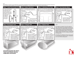
HC 2500 Controller with electric control unit
(EVC, CB)
Active boom width is calculated automatically when the boom sections are
operated.
NOTE: Extended menu setting:
[ON/OFF valve ] is [ Not present ] for EVC and CB.
[Pressure system] is [No equalisation]
See “Extended menu”.
1. HC 2500 display
2. Display connector cable
3. To 12 Volt power supply
4. Area switch (option)
5. Speed transducer
6. Flow transducer
7. Box connector socket
8. Spray box for electric con-
trol unit
9. 39 pin plug to control unit
10. Electric control unit
Power supply
The power supply is 12 Volt DC.
Brown wire is positive “ t ”.
Blue wire is negative “ - ”.
Power supply must come directly from the battery. The wires must have a
cross-sectional area of at least 1.0 mm2 to ensure sucient power supply.
NOTE: Do not connect to the starter motor or generator/alternator. Warranty
is void if this is done.
Use the HARDI Electric distribution box (Ref. no. 817925) if the tractor has a
doubtful wiring.

7
B
A
C
B
D
A
A
C
C
Display
The display is tted in the tractor cabin
at a convenient place.
The mounting rod (A) is utilised to t
the display together with the Spray
box.
Place “ Quick guide”
sticker at C
NOTE: Power must be disconnected before
wire harness (B) is connected to the display.
The wire harness has identication labels
D for dierent connections. Connect up
specic to your version.

8
Transducer pin and wire connections
HARDI transducers colour codes
are as follows. Includes speed, ow,
area meter, revolutions and pres-
sure transducers.
Speed transducer for tractor
Note the following if the speed transducer is
tted to the tractor or vehicle.
The speed transducer is an inductive type. It
requires a metallic protrusion (e.g. bolt head)
to pass by it to trigger a signal. A diode on the
transducer will ash when a signal is detected.
Recommended distance between protrusion
and transducer is 3 to 5 mm.

9
BK BK
EVC
Flow transducer for BK and EVC control unit
For BK and EVC control unit, the housing is tted just prior to the distribution
valves. Flow transducer is tted to the housing and connected to the Scanbox
with the a 3 poled plug.

10
T165-0005
T165-0006
5-7 mm
5-7 mm
Optional transducers
Revolutions and area-meter transducer
The south side of the magnet
must face the transducer.
Distance between them must
be 5 to 7 mm.
An adjustable hose clamp
drilled with a 4.5 mm hole can
be used to attach the magnet
to the shaft.
Analog transducer
This is for example a pressure
transducer.
Input is 4 to 20 mA.
Transducer cables are fed through the grommets. Connection is directly to the
junction box circuit board.
Cables
All the cables and wires must be routed so they do not get pinched, snagged
or melted.
NOTE: An extension cable is available as an option if the computer is to be
placed further away from the Spray control box. (Ref. no. 261933)
NOTE: Although the system meets standards EN 50081-1 (1992) for generic
emission and EN 50082-2 (1995) for generic immunity, some communication
systems (e.g. 2 way radio, cellular telephones) may cause interference with the
sprayer computer. Keep communication system units and cabling away from
the sprayer computer units and cabling. If interference is noted, avoid using the
communication system.

11
5
4
3
1
2
C H A N G E V O L . R A T E
xxx L/ha
Start-up
After connecting the plugs, the power is turned on at the Spray box or power
supply. Model, version number and boom sections and size is displayed briey.
Display
1. Matrix display, upper line.
2. Matrix display, lower line.
3. Key for menu.
4. Arrow keys.
• For programmed application rate.
With HM 1500, the value is used for the dose alarm.
• To get to (scroll).
• To alter a parameter.
5. Key to accept or get out of a menu.
NOTE: Press the keys with the underside of your nger.
Avoid using your ngernail.
Reading chosen volume rate
To read the chosen volume rate, press briey either arrow keys
on the display. The chosen rate is shown.
The main picture will return again after 5 seconds or if you press
accept key.
HM 1500: Changing the desired volume rate for alarm
The desired rate must be entered if you wish to operate with the alarm. Press
either arrow keys on the display. The rate per area is shown.
If the key is pressed again it will raise or lower the chosen rate.
When the key is released the display shows the new rate for a moment and
then returns to the main picture.
HC 2500: Changing the volume rate
The rate can be changed:
• Automatically, by changing the desired rate on the HC 2500 display.
• Manually, by raising and lowering the pressure on the control box.

12
M A N .
A r e a x x x x . x x h a
Y xxxxx L
Automatic dosage
To alter the chosen application rate, press either arrow keys on the display. The
chosen quantity applied per area unit is shown. If the key is pressed again it
will raise or lower the chosen rate. When the key is released the display shows
the new rate for a moment and then returns to the main picture.
NOTE: A minimum speed of 2.0 km/h is needed before the system will regu-
late automatically.
Manual dosage
To dose in manual mode, use the pressure switch on the control box. With HC
2500, the manual mode is indicated on the bottom line with a ashed text [
MAN. ] over the displayed information. Bottom line is cleared when [ MAN. ] is
displayed.
To go from manual to automatic dosage, briey touch the arrow key
on the HC 2500.
Reading and reset of area trip
Area trip from 1 to 8 (Y) can be used for individual areas.
Area trip 0 is a tally of area trips 1 to 8. The treated area is memorised when the
system is switched o.
1. Press enter key for area covered and volume sprayed.
2. Press enter key again to return. If is not pressed again it will return
to the main picture after 15 seconds.
To reset the active register press the enter key continuously and a
5 second countdown will commence.
Reset of a register can be stopped if the enter key is released.
Alarms
Alarm warnings [ Vol. rate alarm ] or [ Tank alarm ] are ashed for 3 seconds
at a time on the top line over the displayed information.

13
Press Repeat to exit the menus and go back to the normal display
function.
Press to continue in the menu if needed.
Press to accept and exit the menu.
Press to nd desired sub-menu or alter parameter.
Press to enter menu.
Press to nd desired menu.
Press to enter menus.
Menus
Parameter selection is carried out from the menu key.
The menus can be scrolled to and fro with the arrow keys.
The upper line, in capital letters, displays the menu you are in.
The lower line, in small letters, displays the choices you have. When the chosen
menu is shown, press the menu key again to open the menu.
When modifying a parameter, prolonged pressure on the arrow key will gener-
ally cause the data shown on the display to alter faster.
After the parameter is modied, press the accept key.
The display then changes back to the previous picture.
Press the accept key until the display returns to the main display.
There are 2 menu systems, the operator menu for general use and an extended
menu for initial set-up of the system. To access the extended menu, press both
arrow keys at the same time until the menu changes.
General key

14
Display readout
Tank contents
Calibration
Alarms
Area/volume trip
Sensor test
Volume rate
Program : Actual
Tank contents
Flow rate
Optional sensor
Revolutions
Speed
Active boom size
Flow calibration
Speed calibration
Revolutions
Boom sections/size
Volume rate
Tank
Area 0 to 8
Flow
Speed
Area switch test
Revolutions
Optional sensor
Keystroke menu tree chart
Press to read or alter (HC 2500) chosen volume rate.
Press to read or reset area trip.
Main menu

15
T a n k c o n t e n t s
C a l i b r a t i o n
A l a r m s
A r e a / v o l u m e t r i p
Sensor test
MAIN MENU
Display readout
Main menu
The upper line will read [ MAIN MENU ].
The lower line displays the choices.
To choose what is to be displayed on screen.
To change the indicated tank contents.
To access calibration menus.
To set alarm parameters.
To select register to record or read area covered and volume sprayed.
To test that the transducers function.

16
S h o w h e r e
Show here
D I S P L A Y R E A D O U T
V o l u m e r a t e
T a n k c o n t e n t s
P r o g r a m : A c t u a l
F l o w r a t e
Display readout
It is possible to freely choose which function is to be shown on the upper or
lower line of the display.
To choose where to show information.
Press arrow key to move [ Show here ] from the upper to lower line. Press
menu key to continue.
The upper line will read [ DISPLAY READOUT ].
The lower line displays the choices.
To show the actual application rate.
To show the programmed and actual application rate.
To show the tank contents.
If two tanks are used, the tank contents is the total contents.
To show the ow rate.

17
R e v o l u t i o n s
O p t i o n a l s e n s o r
Speed
Active boom size
T A N K C O N T E N T S
xxxx L
To show readout from optional analog transducer.
To show revolutions.
To show driving speed.
To see the active boom size.
Tank contents
If the sprayer is partially relled or relled the tank contents can be adjusted.
See Extended menu to set tank size.
Press menu key and use arrow keys to raise or lower value.

18
C A L I B R A T I O N
Boom size set
B O O M S I Z E S E T
Total sections x
S e c . y S i z e x . x x m
C A L I B R A T I O N
Flow calibration
Calibration
It is necessary to set the correct boom width and calibrate the ow and speed
transducer before using the system. Calibration of the optional revolutions
transducer is necessary if it is tted.
Boom size
For setting of number of boom sections and width.
Correct work width for each boom section is necessary
to calculate dosage and area covered.
Method
1. Use arrow key to set number of boom sections and press menu key.
Maximum number of sections is 8. Press menu key to continue.
For mistblowers, number of sections is typically 2.
2. Use the arrow key to increase or decrease section work width.
Press menu key to continue to next boom section.
After the last section, press the accept key.
The display will briey show the total width.
NOTE: End nozzles, if tted, are not part of the boom. When the end nozzles is
spraying, the volume rate under the boom will be reduced.
Flow calibration
/