Page is loading ...

ESTATE SPRAYERS
GAS ENGINE
Operator's Manual
67301103 (6/01)


1
HARDI® reserves the right to make changes in design,
material, or specification without notice thereof.
HARDI® and other product names are registered trademarks
of HARDI® Inc. in the U.S. and in other countries.
ESTATE SPRAYERS
GAS ENGINE
Operator’s Manual
67301103 (6/01)

2HARDI® GAS ENGINE ESTATE SPRAYER OPERATOR’S MANUAL
TABLE OF CONTENTS
1.0 INTRODUCTION................................................................................ 4
2.0 SAFETY INFORMATION................................................................... 6
2.1
Follow Safety Instructions ..................................................................
7
2.2
Operating The Sprayer Safely ...........................................................
7
2.3 Handling Chemical Products Safely ............................................. 8
2.4 Local Poison Information Center .................................................. 9
3.0 HOOKING UP THE SPRAYER ....................................................... 10
4.0 OPERATING THE SPRAYER ......................................................... 11
4.1
Controls ...........................................................................................
11
4.2
ET Manual Control Operation ..........................................................
12
4.3
M600 Brass Manual Control Operation ...........................................
14
5.0 NOZZLE SELECTION ..................................................................... 16
5.1 Handgun Nozzle Selection ......................................................... 16
5.2 Boom Nozzle Selection .............................................................. 16
6.0 CALIBRATION ................................................................................ 18
6.1 Calibration (Ounce Method) ....................................................... 19
7.0 MAINTENANCE............................................................................... 19
7.1 Cleaning The Sprayer ................................................................ 19
7.2 Lubrication .................................................................................. 21
7.3 Nozzle Filters .............................................................................. 22
7.4 Nozzle Tubes and Fittings .......................................................... 22
7.5 Pump Maintenance .................................................................... 22
7.6 Boom Maintenance .................................................................... 23
8.0 STORAGE ....................................................................................... 24
8.1 Preparation After Storage ........................................................... 24
9.0 TROUBLESHOOTING..................................................................... 25
10.0 TECHNICAL SPECIFICATIONS ................................................... 26
10.1 HARDI® Diaphragm Pump Specifications ................................ 26
10.2 Sprayer Specifications .............................................................. 27
10.3 Safety Decals ........................................................................... 27
11.0 PARTS DRAWINGS ...................................................................... 28
12.0 WARRANTY POLICY AND CONDITIONS ................................... 41
13.0 NOTES ........................................................................................... 43

3
HARDI® GAS ENGINE ESTATE SPRAYER OPERATOR’S MANUAL
Dear Owner,
Thank you for purchasing a HARDI® product and welcome to the ever-
increasing family of HARDI® equipment owners.
Our sprayers and accessories are rapidly becoming a familiar sight on
North American farms and estates. We believe that this results from
growers becoming increasingly conscious of crop protection input costs
and the vital need for cost effective application equipment.
Please take the time to thoroughly read the Operator’s Manual before
using your equipment. You will find many helpful hints as well as
important safety and operation information.
Some of the features on your HARDI® Estate Sprayer were suggested
by growers. There is no substitute for “on farm” experience and we
invite your comments and suggestions.
Please address your correspondence to the Service Manager at one of
these branches:
Sincerely,
Tom L. Kinzenbaw
President
HARDI® MIDWEST
1500 West 76th St.
Davenport, Iowa 52806
Phone: (319) 386-1730
Fax: (319) 386-1710
HARDI® GREAT LAKES
290 Sovereign Rd.
London, Ontario N6M 1B3
Phone: (519) 659-2771
Fax: (519) 659-2821
HARDI® WEST COAST
5646 W. Barstow, Suite 101
Fresno, California 93722
Phone: (559) 271-3106
Fax: (559) 271-3107

4HARDI® GAS ENGINE ESTATE SPRAYER OPERATOR’S MANUAL
1.0 INTRODUCTION
We congratulate you for choosing a HARDI® plant protection product.
The reliability and efficiency of this product depends on your care. The
first step is to carefully read and pay attention to this operator’s
manual. It contains essential information for the efficient use and long
life of this quality product.
This manual covers the HARDI® Estate Sprayers equipped with Briggs
& Stratton or Honda gas engines directly coupled to HARDI® 500 or
600 diaphragm pumps. These sprayers include the ES 50, ES 80, SM
50 and SM 80 models.
The heart of your sprayer is the diaphragm pump. The design is
simple, resulting in low maintenance requirements and guaranteed
pump life. The bearings and crankshaft are grease lubricated and are
therefore protected from spray solution if any diaphragm fails in ser-
vice. A drain hole is located in the base of the crank case to facilitate
the draining of any foreign matter. The pump is self-priming and can be
run dry without damage.
The ES 50 and ES 80 sprayers are equipped with the ET manual
control which features: on/off control for boom and handgun, pressure
adjustment, pump bypass agitation, remote pressure safety valve and
a 2-1/2” pressure gauge.
The SM 50 and SM 80 sprayers are equipped with the M600 Brass
manual control which features: on/off control for handgun/(optional
boom), pressure adjustment, pump bypass agitation, integral pressure
safety valve and a 2-1/2” pressure gauge.
The tanks, made of impact proof and chemical resistant polyethylene,
have a purposeful design with rounded contours which allows for
efficient cleaning and draining. They are designed with a large deep
sump so that they can be completely emptied even when the sprayer is
used on slopes. A drain plug is provided in the sump to assist cleaning
of the tank. The tanks are equipped with a top suction filter which can
be inspected and cleaned without emptying the tank.
Also covered in this manual are the 6’ FD and 14’ HD booms which
feature fore and aft breakaways. The 6’ FD boom folds vertically and
the 14’ HD boom folds horizontally forward. Both booms feature ISO
flat fan nozzles with 20” spacing.

5
HARDI® GAS ENGINE ESTATE SPRAYER OPERATOR’S MANUAL
The frame and boom of your estate sprayer are finished with a powder
coat paint which provides maximum protection from chemicals and
rust.
The model 60L spraygun features an adjustable spray nozzle for
varying the spray width. The standard spraygun features 25’ of 1/2”
hose on the hose wrap (optional 40’).
Since this book covers options available for several different Estate
Sprayers, please pay attention to the sections dealing specifically with
your model.
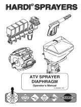
SM 80 with Spraygun
and Hose Wrap
SM 80 with Spraygun
and Hose Reel
ES 80 with 14‘ HD Boom

6HARDI® GAS ENGINE ESTATE SPRAYER OPERATOR’S MANUAL
2.0 SAFETY INFORMATION
WARNING!
ALWAYS READ THE OPERATOR’S MANUAL BEFORE
USING THIS EQUIPMENT
DO NOT REMOVE ANY SAFETY DEVICES OR
SHIELDS. NEVER SERVICE, CLEAN OR REPAIR A
MACHINE WHILE IT IS OPERATING
WARNING!
ALWAYS WATCH FOR THIS SYMBOL TO POINT OUT
IMPORTANT SAFETY PRECAUTIONS
IT MEANS ATTENTION! BECOME ALERT!
YOUR SAFETY IS INVOLVED!

7
HARDI® GAS ENGINE ESTATE SPRAYER OPERATOR’S MANUAL
2.1 Follow Safety Instructions
1. Carefully read all the safety messages in this manual and the
safety labels fitted to the machine. Keep safety labels in good
condition. Replace missing or damaged safety labels. Make sure
that new equipment components include any current safety labels.
Replacement safety labels are available from your authorized
HARDI® dealer.
2. Learn how to operate the sprayer and how to use the controls
properly. Do not let anyone operate the sprayer without proper
instructions.
3. Keep your sprayer in proper working condition. Unauthorized
modifications or use may impair the function and/or safety and
affect the machine’s life.
4. If you do not understand any part of this manual and need assis-
tance, please contact your authorized HARDI® dealer.
2.2 Operating The Sprayer Safely
1. Read the complete manual carefully and become familiar with the
operation of the equipment before initial operation in each spray-
ing season. Failure to do so may result in possible over or under
application of spray solution and may lead to personal injury.
2. Always keep children away from your estate sprayer.
3. Never pull your estate sprayer behind a truck on public roads.
Load the sprayer onto a trailer or into the back of a truck for
transporting.
4. Understand service procedures before undertaking any mainte-
nance. Never lubricate, service, or adjust the machine while it’s
moving. Securely support any components before working on
them.
5. Keep all parts in good condition and properly installed. Repair
damaged parts immediately. Replace worn or broken parts.
RECOGNIZE SAFETY INFORMATION
This is the Safety-alert symbol. When you see this
symbol on your machine or in this manual, be alert
to the potential for personal injury.
Follow recommended precautions and safe operating practices.

8HARDI® GAS ENGINE ESTATE SPRAYER OPERATOR’S MANUAL
2.3 Handling Chemical Products Safely
1. Direct exposure to hazardous chemicals can cause serious injury.
These chemicals can include lubricants, coolants, paints, adhe-
sives and agricultural chemicals. Material Safety Data Sheets
(M.S.D.S.) are available for all hazardous chemicals which inform
the user of specific details including, physical and health hazards,
safety procedures, and emergency response techniques.
2. Protective clothing such as rubber gloves, goggles, coveralls and
respirator must be worn while handling chemicals. All protective
clothing should be kept in excellent condition and cleaned regu-
larly or discarded.
3. If chemicals come in contact with any exposed skin areas, wash
immediately with clean water and detergent. Never place nozzle
tips or any other components that have been exposed to chemi-
cals to lips to blow out obstructions. Use a soft brush to clean
spray nozzles.
4. Dedicate an area to fill, flush, calibrate and decontaminate sprayer
where chemicals will not drift or run off to contaminate people,
animals, vegetation, water supply, etc. Locate this area where
there is no chance of children coming in contact with this residue.
5. Decontaminate equipment used in mixing, transferring and
applying chemicals after use. Follow the instructions on the
chemical label for the correct procedure required. Wash spray
residue from outside of the sprayer to prevent corrosion.
6. Extreme care should be taken in measuring spray products.
Powders should be used in suitable sized packages or weighed
accurately. Liquids should be poured into a suitable graduated
container. Keep chemical containers low when pouring. Wear a
filtered respirator and let the wind blow away from you to avoid
dust and/or splashes contacting the skin or hair.
7. Store chemicals in a separate, plainly marked locked building.
Keep the chemical in its original container with the label intact.
8. Dispose all empty containers after rinsing in accordance with local
regulations & by-laws. Dispose of all unused chemicals and left
over fertilizer in an approved manner
9. Keep a first aid kit and fire extinguisher available at all times when
handling chemicals.

9
HARDI® GAS ENGINE ESTATE SPRAYER OPERATOR’S MANUAL
2.4 Local Poison Information Center
PHONE NO. _________ - _________ - _____________
Find the phone number for the poison control center in your phone book
and write it in the space above.
Keep a list, in the space provided below, of all the chemicals that you have
in use.
1. ___________________________________________________
2. ___________________________________________________
3. ___________________________________________________
4. ___________________________________________________
5. ___________________________________________________
6. ___________________________________________________
7. ___________________________________________________
8. ___________________________________________________
9. ___________________________________________________
10. ___________________________________________________

10 HARDI® GAS ENGINE ESTATE SPRAYER OPERATOR’S MANUAL
3.0 HOOKING UP THE SPRAYER
TOW VEHICLE REQUIREMENTS:
Lawn & Garden tractor or ATV with a drawbar with sufficient horse-
power and braking ability to safely control the following specifications:
1. ES 50 and ES 80: Attach sprayer tongue to drawbar with the
correct size drawbar pin and install safety clip.
SM 50 and SM 80: Secure sprayer to bed of truck/utility vehicle.
WARNING:
MAKE SURE THAT YOUR SKID MOUNT SPRAYER IS
PROPERLY SECURED AND THAT YOUR TRUCK/UTILITY
VEHICLE HAS SUFFICIENT CARRYING CAPACITY FOR YOUR
SPRAYER PLUS THE WEIGHT OF THE SPRAY LIQUID.
IMPORTANT:
The HARDI® Estate sprayers equipped with gas en-
gines are shipped from the factory without oil in the engine crankcase
or reduction gearbox.
2. Before operating the gas engine, you must:
A. Check the engine crankcase oil level.
B. Check the reduction gearbox oil level.
C. Fill the gas tank.
D. Make sure engine air filter is not plugged.
3. Refer to gas engine operating manual for oil change and mainte-
nance information.
4. Tire pressure should be 10 PSI (ES 50, ES 80 only).
Sprayer
ES 50
ES 80
92
66
Tongue Weight (lbs.)Total Loaded Weight (lbs.)
634
940
Sprayer
SM 50
SM 80
Total Loaded Weight (lbs.)
616
852

11
HARDI® GAS ENGINE ESTATE SPRAYER OPERATOR’S MANUAL
4.0 OPERATING THE SPRAYER
WARNING:
ALWAYS FILL YOUR ESTATE SPRAYER WITH CLEAN
WATER ONLY. ALWAYS FILL WATER THROUGH THE STRAINER
BASKET TO PREVENT FOREIGN PARTICLES FROM ENTERING
THE TANK. NEVER LET THE FILLING HOSE ENTER THE TANK.
CHEMICALS MAY CONTAMINATE THE WATER SUPPLY LINES,
PLANT AND/OR WELL.
4.1 CONTROLS
The ES and SM series estate sprayers use different controls for
operating. The ES 50 and ES 80 sprayers use the ET manual control
(Section 4.2), while the SM 50 and SM 80 use the M600 brass manual
control (Section 4.3).

12 HARDI® GAS ENGINE ESTATE SPRAYER OPERATOR’S MANUAL
4.2 ET MANUAL CONTROL OPERATION (ES 50/80)
Boom Operation
1. Locate your sprayer in a suitable location to spray water from the
boom and/or handgun.
2. Fill the tank with clean water.
3. Turn dial 1 (Fig. 2) counter clockwise all the way out.
4. Set boom switch 2 (Fig. 2) on and spraygun switch 3 (Fig. 2) off.
5. Start the engine.
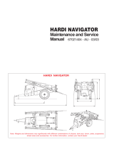
Fluid System Overview
When the 500/600 pump A (Fig 1) is running, pressurized fluid flows
from the tank to the distribution valves B (Fig 1). Fluid that is not
required for use by the boom or spraygun is returned to the tank
through the bypass line and agitation nozzle F (Fig 1). When the boom
valve is open, fluid flows to the boom D (Fig 1). When the spraygun
valve is open and the red handle on the spraygun is depressed, fluid
flows to the spraygun C (Fig 1). If the boom and spraygun valves are
off and the pressure valve is set too low to handle the output from the
pump, the safety valve E (Fig 1) opens to allow the fluid to return to the
tank.
A. 500/600 Pump
B. Distribution Valves
C. Spraygun
D. Boom
E. Safety Valve
F. Agitation Fig. 1
A
B
C
D
E
TANK
F

13
HARDI® GAS ENGINE ESTATE SPRAYER OPERATOR’S MANUAL
Fig. 2
ON
OFF
6. Increase pressure by turning dial 1 (Fig. 2) clockwise. Watch the
pressure gauge 4 (Fig. 2) until the desired pressure is reached
(turning dial 1 (Fig. 2) counter clockwise decreases pressure).
NOTE: Refer to Section 5.0 for nozzle selection and calibration.
Spraygun Operation
7. To operate the spraygun, turn switch 2 (Fig. 2) off and switch 3
(Fig. 2) on. Then depress the red handle 5 (Fig. 2) to spray water
from the spraygun. Check the pressure on gauge 4 (Fig. 2) and
follow step 6 to adjust.
8.
To adjust the spray pattern, turn the black handle 6 (Fig. 2)
OUT for
a narrow spray pattern for long distances and IN for a wide pattern
for more coverage at close distances.

14 HARDI® GAS ENGINE ESTATE SPRAYER OPERATOR’S MANUAL
4.3 M600 BRASS MANUAL CONTROL OPERATION (SM 50/80)
Spraygun/(Optional Boom) Operation
1. Locate your sprayer in a suitable location to spray water from the
spraygun (and/or optional boom).
2. Fill the tank with clean water.
3. Turn main ON/OFF handle to spraying position 1 (Fig 4).
4. Turn dial 3 (Fig 4) counter clockwise all the way out. This relieves
the pressure on the springs and minimizes start-up problems.
(If optional boom is installed, make sure boom valve 7 (Fig 4) is
closed).
5. Start the engine.
Fluid System Overview
When the 500/600 pump A (Fig 3) is running, pressurized fluid flows
from the tank to the M600 brass manual control B (Fig 3). When the
main ON/OFF valve is “OFF”, fluid is returned to the tank through the
bypass line and agitation nozzle D (Fig 3). When the main ON/OFF
valve is “ON” and the red handle on the spraygun is depressed, fluid
flows to the spraygun C (Fig 3). Optional boom: when main ON/OFF
valve is “ON” and boom valve E* (Fig 4) is open, fluid flows to the
boom F* (Fig 3).
Fig. 3
A
C
F*
TANK
D
BE*
A. 500/600 Pump
B. M600 Control
C. Spraygun
D. Agitation - (Control Valve Bypass)
E*. Boom Valve (Optional)
F*. Boom (Optional)

15
HARDI® GAS ENGINE ESTATE SPRAYER OPERATOR’S MANUAL
6. Increase pressure by turning dial 3 (Fig 4) clockwise. Watch the
pressure gauge 4 (Fig. 4) until the desired pressure is reached
(turning dial 3 (Fig 4) counter clockwise decreases pressure).
7. To operate the spraygun, depress the red handle 5 (Fig 4) to spray
water from the spraygun. Check the pressure on gauge 4 (Fig 4)
and follow step 6 to adjust.
8.
To adjust the spray pattern, turn the black handle 6 (Fig 4)
OUT for
a narrow spray pattern for long distances and IN for a wide pattern
for more coverage at close distances.
9. To stop liquid flow to the spraygun (and optional boom), turn main
ON/OFF handle to position 2 (Fig 4). The entire fluid flow from the
pump will then return to the tank through the by-pass line.
10. To operate optional boom, turn main ON/OFF handle to spraying
position 1 (Fig 4) and open boom valve 7 (Fig 4) to spray water
from the boom. Check the pressure on gauge 4 (Fig 4) and follow
step 6 to adjust.
Fig. 4
CLOSED
OPEN
7

16 HARDI® GAS ENGINE ESTATE SPRAYER OPERATOR’S MANUAL
5.0 NOZZLE SELECTION
As standard equipment with your estate sprayer, nozzles have been
provided for both the handgun and boom.
5.1 Handgun Nozzle Selection
The 1099-20 nozzle (HARDI® ref. no. 371314) is the standard nozzle
for the handgun. This nozzle supplies the following rates in U.S.
gallons per minute at the given pressures:
Other size 1099 nozzles are available from you HARDI® Dealer.
5.2 Boom Nozzle Selection
ISO F-03-110 BLUE nozzles (HARDI® ref. no. 371767) are standard
on the 6’ boom and 14’ boom for gas engine driven systems. If you
find by using the following directions and nozzle chart, that these
nozzles are not the correct size for your spraying needs, other nozzles
are available from your HARDI® Dealer.
NOTE: A Calibration & Nozzles Manual (HARDI® ref. no. 67000103) is
available from your HARDI® dealer which contains more detailed
information for calibration and nozzle selection.
TO USE THE FOLLOWING CHART:
1. You must know your desired forward speed (example 3 MPH).
2. You must know the pressure (PSI) you want to spray at (example
30 PSI).
3. You must know your desired application rate (example 16 gallons
per acre).
0.678
0.829
0.956
1.068
1.169
1.261
1.504
1.840
2.123
PSI
20
30
40
50
60
70
100
150
200
NOZZLE
1099-20 0.538
0.661
0.766
0.857
0.940
1.018
1.222
1.500
1.736
GPM

17
HARDI® GAS ENGINE ESTATE SPRAYER OPERATOR’S MANUAL
KNOWING THESE THREE FACTS, PROCEED AS FOLLOWS:
1. Locate the correct speed column on the chart below (example 3
M.P.H.).
2. Find the number in that column which is closest to your desired
application rate and is also opposite the desired pressure (example
16.8 GPA is closest to 16 GPA and opposite 30 PSI).
3. For this example, you would select the F-02-110 YELLOW nozzle.
NOTE: Using this chart will bring you very close to your desired appli-
cation rate. However, for final pressure setting, you must calibrate your
sprayer (Section 6.0).
50
60
40
30
20 0.11
0.13
0.15
0.17
0.18
16.3
19.3
22.2
25.2
26.7
10.9
12.9
14.8
16.8
17.8
8.2
9.7
11.1
12.6
13.3
6.5
7.7
8.9
10.1
10.7
5.4
6.4
7.4
8.4
8.9
ISO
F-015-110
GREEN
(371765)
NOZZLE PSI 3 MPH
GPA at MPH
2 MPHGPM 6 MPH5 MPH4 MPH
50
60
40
30
20 0.071
0.087
0.100
0.113
0.122
10.5
12.9
14.8
16.8
18.1
7.0
8.6
9.9
11.2
12.1
5.3
6.5
7.4
8.4
9.1
4.2
5.2
5.9
6.7
7.2
3.5
4.3
5.0
5.6
6.0
ISO
F-01-110
ORANGE
(371764)
50
60
40
30
20 0.14
0.17
0.20
0.23
0.24
20.8
25.2
29.7
34.1
35.6
13.9
16.8
19.8
22.8
23.8
10.4
12.6
14.8
17.1
17.8
8.3
10.1
11.9
13.7
14.3
6.9
8.4
9.9
11.4
11.9
ISO
F-02-110
YELLOW
(371766)
50
60
40
30
20 0.21
0.26
0.30
0.34
0.37
31.1
38.6
44.6
50.5
54.9
20.8
25.7
29.7
33.7
36.6
15.6
19.3
22.3
25.2
27.5
12.5
15.4
17.8
20.2
22.0
10.4
12.9
14.8
16.8
18.3
ISO
F-03-110
BLUE
(371767)
HARDI® ISO F-110 SPRAY SYNTAL NOZZLES

18 HARDI® GAS ENGINE ESTATE SPRAYER OPERATOR’S MANUAL
6.0 CALIBRATION
WARNING:
ALWAYS CALIBRATE YOUR SPRAYER WITH CLEAN
WATER ONLY! WEAR PROTECTIVE CLOTHING SUCH AS RUB-
BER GLOVES, GOGGLES AND COVERALLS.
Why must you calibrate a sprayer?
A nozzle selection chart will tell you what application rate you should
expect. Variations due to nozzle wear, errors in pressure adjustment,
and tractor speedometer can result in a large error in application rate.
How do you calibrate a sprayer?
Calibration kits are available from HARDI®, #818493 for U.S. Gallons
and #818492 for metric calibration. For accurate calibration, the
sprayer is driven a specific distance at spraying speed and the length
of time is recorded. The operator then measures the amount of water
sprayed from one nozzle at spraying pressure for the same length of
time noted. The amount of water sprayed provides a direct reading of
application rate. Slight adjustments are then made by varying the
pressure.
Here are some tips to remember when using the calibration kit method:
1. Calibrate with clean water only.
2. Follow the instructions in the calibration kit carefully.
3. Before calibration, check the flow of each nozzle. If it puts out more
than 10% of its original volume, replace it.
4. When determining the length of time required to drive a recom-
mended distance, drive in actual field or lawn conditions with a half full
sprayer. Repeat the test several times, then take the average of the
times recorded.
5. Calibration of the sprayer should be completed at the beginning of
the season and repeated every 2 to 3 full days of spraying, and every
time you change volume rate or use different nozzles.
NOTE: A Calibration & Nozzles Manual (HARDI® ref. no. 67000103) is
available from your HARDI® dealer which contains more detailed
information for calibration and nozzle selection.
/