Aerotech SUMO Assembly And Operation Instructions Manual

Category
Toys
Type
Assembly And Operation Instructions Manual

Aerotech SUMO is an advanced high power model rocket, designed for experienced rocketeers. This single-stage rocket features a 29mm motor mount, allowing for the use of a wide range of high-power motors. With its tapered swept fins and compound airfoil, the SUMO provides excellent stability and control during flight. The rocket's lightweight construction of 32 ounces (without motor) ensures efficient performance, while the sturdy 42-inch parachute provides reliable recovery.

Aerotech SUMO is an advanced high power model rocket, designed for experienced rocketeers. This single-stage rocket features a 29mm motor mount, allowing for the use of a wide range of high-power motors. With its tapered swept fins and compound airfoil, the SUMO provides excellent stability and control during flight. The rocket's lightweight construction of 32 ounces (without motor) ensures efficient performance, while the sturdy 42-inch parachute provides reliable recovery.

ADVANCED HIGH POWER MODEL ROCKET
ASSEMBLY AND OPERATION INSTRUCTIONS
BEFORE YOU BEGIN:
Study the illustrations and sequence of assembly. The
sequence of assembly is important. Review the parts list and
become familiar with all parts before assembly. If any parts
are missing or damaged, contact RCS @ (435) 865-7100 or
through our web site @ www.aerotech-rocketry.com.
DO NOT MODIFY THE DESIGN OF THE ROCKET.
Changes to the design of the rocket such as, but not limited to,
reducing the fin size, shortening the body tube, or modifying
the motor tube assembly can adversely affect the flight stabil-
ity of the rocket and may void this products warranty.
Only use AEROTECH™ Composite Model Rocket Motors
in this High Power rocket. See box label for recommended
motors.
Read and follow the Model Rocket Safety Code of the National Association of Rocketry
(NAR) and comply with all federal, state, and local laws in all activities with model rockets.
PARTS LIST
COMPLETED
SUMO™
LEVEL 1
MODEL ROCKET
Cap, Piston (14006) 1
Sleeve, Piston (14007) 1
Motor tube (12”/30.5cm) (12912) 1
Motor Hook (19001-Y) 1
FIN-LOK™ rings-4 fin (19344) 2
Centering rings (3.896” O.D.) (14029) 3
Fins (11715) 4
Bulkhead Disc (2.540”) (16609) 1
Spacer, HP Motor (Black tube) (14015) 1
Spacer, Hobby Motor (Yellow tube) (14014) 1
Ejection gas baffle (19030) 1
Screw eye (19015) 1
Shock cord (18’) (17201) 1
Body tube (4” x 23”) (14040) 1
Launch lugs (19035) 2
Nose cone (9 oz.) (11405) 1
Parachute (42” diameter) (13042) 1
Buckle, Cord Retaining (17150) 2
Decal Sheet (18023) 1
Instructions, Sumo (19924) 1
Read And Follow
All Instructions
ADDITIONAL MATERIALS AND TOOLS REQUIRED
12” Ruler (with 1/16” resolution)
Medium viscosity cyanoacrylate (cyano’) cement AND
5 to 15 minute cure epoxy
Hobby knife
Description Part # Qty Description Part # Qty
1
19924 SUMO KIT REV: 8/04
Designed by Ed LaCroix,
Jason Blatzheim,
and Bobby Rosenfield
1/8” Wood dowel at least 12” long
#240 / #400 Grit sandpaper
Masking Tape (3/4” AND 1” wide)
Division of RCS Rocket Motor Components, Inc.
'RCS' SUMO INSTRUCTIONS 8/16/04, 9:52 AM1
1-15/16”
4”
MOTOR TUBE LAYOUT
Back Edge of
Motor Tube
Front Edge of
Back FIN-LOK™
Ring
Back Edge of
Front FIN-LOK™
Ring
1/4”
LOCATION
GUIDE
Using the Location Guide, make a mark along the motor
tube line 4” from the back end of the motor tube. This mark
locates where the back edge of the front FIN-LOK™ ring
will be. Make another mark 1-15/16” from the back end of
the motor tube. This mark locates where the front edge of
the rear most FIN-LOK™ ring will be.
1.
FIN-LOK™/ LABYRINTH ASSEMBLY
2
1.
NOTE: FROM THIS POINT ON, DO NOT USE ANY
CEMENT UNTIL REACHING ASSEMBLY STEP 5.
Slide the motor hook, centering ring, and FIN-LOK™ ring
over the rear end of the motor tube. The tab of the motor
hook will be facing up and rest against the forward face
of the centering ring. Push on the FIN-LOK™ ring until the
back edge of the FIN-LOK™ ring is moved to the forward
most mark made in Step 1 above. (NOTE: The rings are
designed to be a tight fit on the motor tube. If the rings are
difficult to slide onto the motor tube, round the inside edges
of the rings with sandpaper. If the FIN-LOK™ rings need to
be turned after they are on the motor tube,
use a small piece of cloth to provide a better grip.)
Slide the other FIN-LOK™ ring over the back end of the
motor tube. Push on the FIN-LOK™ ring until the front edge
of the FIN-LOK™ ring is at the rear most mark made in Step
1 above.
Using the line on the motor tube as a guide, gently twist the
fin locks of the back FIN-LOK™ ring until they are aligned
with the fin locks of the front FIN-LOK™ ring.
2.
3.
FIN-LOK™ Ring Location Marks
1-15/16” and 4” from Back Edge
Of Motor Tube
Motor Tube
Front End
FIN-LOK™
Rings
Middle Centering ring
19924 SUMO KIT REV: 8/04
Motor Tube
FIN-LOK™
Ring
Motor Tube
Front End
Motor Hook
Middle Centering Ring
NOTE: This motor tube assembly does not require thrust
rings or a slot for the motor hook. Motor spacing is accom-
plished with the yellow and black spacer tubes for RMS
motors, or masking tape for Single Use motors. This allows
the use of the widest range of motors manufactured by
Aerotech. No cooling mesh to be used.
'RCS' SUMO INSTRUCTIONS 8/16/04, 9:52 AM2
3
FIN-LOK™ / LABYRINTH™ ASSEMBLY (CONT’D)
Test the proper positioning and alignment of the FIN-LOK™
rings by snapping the fins into the fin locks. If any fin does
not snap into place, check to see that each FIN-LOK™ ring
is the correct distance from the back end of the motor tube
and that the fin has no plastic flashing left from production
that may be preventing a proper fit. Remove any plastic
flashing with a hobby knife or sandpaper. After making
any adjustments, carefully remove the fins. Check that the
middle centering ring is still positioned next to and touching
the front FIN-LOK™ ring.
Apply a bead of cement where the middle centering ring
meets the motor tube. Without getting cement into any of
the fin locks, apply cement only to the areas BETWEEN the
fin locks where the front FIN-LOK™ ring meets the middle
centering ring and the motor tube.
Without getting cement into any of the fin locks, apply
cement only to the areas BETWEEN the where only the
front edge of the back FIN-LOK™ ring meets the motor
tube. DO NOT apply cement to the back edge of the
back FIN-LOK™ ring. (NOTE: The unique AEROTECH FIN-
LOK™ fin mounting system carries and distributes aero-
dynamic and thrust loads throughout an integrated rocket
structure in a manner found in large aerospace vehicles.
Loads are primarily borne by structural members and not
cement.)
4.
5.
Make four 1/4” (6mm) long cuts, 90 degrees apart, in the
front end of the motor tube.
Apply a thin film of cement to the front 2/3rd’s of the shoul-
der of the ejection gas baffle and insert the baffle shoulder
all the way into the front of the motor tube. Cement the front
centering ring on top of the ejection baffle as shown. Apply
beads of cement where the baffle meets the motor tube and
into each of the cuts in the motor tube.
6.
7.
8.
Fin Locks
Cement Beads
Middle Centering Ring
DO NOT ALLOW CEMENT
TO GET IN THE FIN LOCKS
1/4”/ 6mm Cuts
Ejection Gas
Baffle Shoulder
19924 SUMO KIT REV: 8/04
Front Centering RIng
Motor Hook Tab Facing Up
'RCS' SUMO INSTRUCTIONS 8/16/04, 9:52 AM3
CENTERING RING / DISC INSTALLATION
Rear Centering Ring
Shock Cord
Motor Tube Assembly
BODY AND FIN ASSEMBLY
Using a hobby knife, carefully remove any body tube mate-
rial that may still be attached to any pre-cut slots in the
body tube.
Insert the motor tube assembly into the back of the rocket
body tube as shown. Position the motor tube assembly so
that the fin locks are located under and visible through the
body tube’s pre-cut fin slots.
Apply cement along the full length of the fin root of a fin
(area of the fin that makes contact with the outside surface
of the body tube). Carefully insert the fin through a slot in the
body tube and snap the fin into place. Repeat this process
for the other three fins. Apply glue fillets at the body and
fin joints.
1.
2.
3.
(NOTE: Each fin should be snug against the body tube.)
Through the back end of the body tube, apply cement where
the fin tabs meet the motor tube, fin locks, and body tube.
Through the front end of the body tube, carefully apply
cement where the front centering ring meets the inside sur-
face of the body tube. This must be an airtight seal.
Lightly sand the surface of the body tube around the launch
lug slots. Apply cement to the base of a launch lug. With the
sloping portion of the launch lug facing toward the front of the
body tube, insert the tab on the bottom of the lug into one
of the pre-cut launch lug slots in the body tube. Repeat this
process for the other launch lug.
4.
5.
1. Slide the rear centering ring over the back of the motor tube and push it against the back FIN-LOK™ ring. Apply a bead of cement
where the centering ring meets the body tube and the motor tube. Securely tie an end of the shock cord to the screw eye with a
square knot. Do not put cement on the knot of the shock cord. Screw the screw eye through the bulkhead disc and then into the
hole in the ejection baffle until tight. Do not glue the screw eye into the ejection baffle.
4
Motor Tube
Assembly
Fin
FIN-LOK™ Tab
Fin Slot
Fin Root
Launch
Lug Slot
Launch Lug
Body Tube
19924 SUMO KIT REV: 8/04
PISTON ASSEMBLY
Piston Cap Recessed 3/8”
From End of Piston Sleeve
Epoxy the Piston Cap inside the Piston Sleeve recessed 3/8” from one end.(Use the black spacer tube as a support for this
operation.) When dry, apply epoxy fillets to both sides of the Cap/Sleeve joints. Do not allow any epoxy to drip on the outside
diameter of the Piston Assembly which could interfere with it’s intended operational movement.
2.
2.5” Bulkhead Disc
Screw Eye
'RCS' SUMO INSTRUCTIONS 8/16/04, 9:53 AM4
VEHICLE DATA
Length: 39”
Diameter: 4.0”
Weight (Without Motor): 32 oz
Nose Cone: 4:1 Ogive
Fins: 4-Tapered swept with compound airfoil
Stages: 1
Motor Mount: 29mm
Recovery System: 42” Parachute
Kit part number: 89024
5
19924 SUMO KIT REV: 8/04
PARACHUTE INSTALLATION
Shroud Line Loops
Fabric Canopy
PISTON ASSEMBLY INSTALLATION
Install Buckles on
Each Side of the
Piston Cap
Piston Assembly
CUTAWAY VIEW OF COMPLETED SUMO™
When the Piston Assembly is completely cured, slide one buckle over the shock cord approximately 6 feet from the end
of the body tube. Then slide the Piston Assembly over the shock cord (Piston Cap facing forward as shown) and slide the
other buckle over the shock cord within one inch of the Piston Assembly. Securely tie the loose end of the shock cord to
the molded loop on the nose cone with a square knot. Do not apply cement to the knot on the shock cord.
Fasten the fabric parachute to the shock cord at a point about one (1) foot away from the nose cone in the following
manner: Stretch out the shroud lines of the parachute so that the lines form three (3) loops one on top of the other. Lay
the shock cord across all the shroud lines. Pass the canopy of the parachute over the shock cord and through the three
(3) loops made by the shroud lines and pull tight. Pack the parachute and insert the nose cone into the body tube.
3.
4.
'RCS' SUMO INSTRUCTIONS 8/16/04, 9:53 AM5
6
OPERATION INSTRUCTIONS
RECOMMENDED MOTORS: Only use AEROTECH composite
model rocket motors when flying your AEROTECH rocket. See the
box label for recommended motors to be used with your SUMO™
rocket .
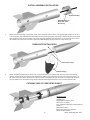
RECOVERY SYSTEM PREPARATION: Bundle the aft end of the
shock cord with a rubber band loosely and insert into the open
end of the Piston Assembly and slide the Piston into the top of the
body tube until it stops against the front centering ring. Roll the
parachute and shroud lines, starting from the canopy peak, into a
loose cylinder that will easily slide into the rocket body tube. Pack
the long portion of the shock cord into the body tube first. Next,
insert the parachute. Finally, insert the short length of shock cord
into the body tube on top of the parachute and put on the nose cone.
Make sure that the parachute, shroud lines, and shock cord are not
caught between the body tube and the shoulder of the nose cone.
The nose cone should slide freely. (NOTE: Extreme hot weather
may make the nose cone a tight fit, however, it will function properly
with the piston ejection system.)
MOTOR PREPARATION: The motors recommended for your
AEROTECH rocket vary in physical size as well as performance.
Prepare your AEROTECH rocket motor according to the instructions
that come with the motor. HP 29mm RMS motors use the black
spacer tube. Hobby 29mm RMS motors use the yellow spacer
tube. Use 3/4” masking tape for single use motor spacing. Be
sure the motor hook snaps in behind the nozzle end of the motor
and holds the motor securely in place. Wrap 1” tape around the
junction of the motor tube and the aft end of the motor to
prevent any possibility of the motor ejecting with all motors.
PRE-LAUNCH CHECKOUT: Before EVERY flight, perform a com-
plete pre-launch checkout of your rocket;
Check that all fins and launch lugs are mounted securely and not
damaged. Examine the body tube and nose cone to make sure they
are free of damage.
Check that the shock cord is securely mounted to the ejection gas
baffle and nose cone, and is in good condition.
See that the nose cone and piston assembly move freely. After awhile,
an ejection residue will build up at the bottom inside surface of the
body tube and the O.D. of the piston . Lightly sand with 400 grit
sandpaper to remove any ejection charge build up.
With the tail of the rocket pointed down and the motor tube empty,
shake the rocket to remove any loose ejection charge debris left from
a previous flight. Periodically, clean the inside of the motor tube to
remove any ejection charge residue.
Be certain the motor to be used is a recommended AEROTECH
model rocket motor of a size appropriate for the launch area.
Be sure the motor hook and motor tube are not damaged and hold
the motor securely in place.
If the pre-launch checkout reveals and damage, repair the damage
before the rocket is flown again.
LAUNCH PAD: Your AEROTECH rocket must be flown from a launch
pad with a 1/4” (6.4mm) diameter metal launch rod at least 36” (0.9m)
long (as measured from the top of the blast deflector), and must be
stable with larger rockets like the Sumo.
MOTOR IGNITION: Only launch your rocket using a remotely con-
trolled and electrically operated launch controller. Keep yourself and
all other people at least 50 feet away from the rocket during launch.
LAUNCH AREA: Launch the rocket in a cleared outdoor area free
of tall trees, power lines, and buildings. The side dimensions of the
cleared area should be at least one half of the projected altitude. An
area for a radius of at least 5 feet (1.5 meters) from the launcher
should be clear of dry grass or other flammable substances. Read
and follow the Model Rocket Safety Code of the National Association
of Rocketry (NAR) and comply with all federal, state, and local laws
in all activities with model rockets. A copy of the NAR safety code is
shown on the instructions that come with all AEROTECH composite
rocket motors.
FLIGHT PROFILE: When the launch button of the electrical launch
controller is pressed, an electrical current causes the igniter to ignite
the composite propellant of the AEROTECH rocket motor. The motor
quickly builds up thrust and powers your AEROTECH rocket into the
air. During powered flight the rocket increases in speed and altitude.
When the propellant burns out the rocket is moving at maximum
velocity and a time delay material (delay grain) inside the motor burns.
While the delay grain burns the rocket coasts to peak altitude at which
point the delay grain ignites the ejection charge within the forward part
of the motor. The ignition of the ejection charge creates a burst of
hot expanding gas which flows around the baffle, and is cooled by
the bulkhead disc attached to the front of the ejection baffle, and then
pressurizes the parachute bay and ejects the piston, nose cone and
parachute. The parachute then deploys and gently returns the rocket
to the ground where the rocket can be prepared for another flight.
TRANSPORT AND STORAGE: To avoid damage to your AEROTECH
rocket during transport, pack it in a box surrounded by soft packing.
Store your rocket at room temperature.
1.
2.
3.
4.
5.
6.
7.
8.
9.
NOTICE: As we cannot control the storage and use of our products, once sold we cannot assume
any responsibility for product storage, transportation, or usage. RCS shall not be held responsible
for any personal injury or property damage resulting from the handling, storage, or use of our
product. The buyer assumes all risks and liabilities therefrom and accepts and uses AeroTech/RCS
products on these conditions.
No warranty either expressed or implied is made regarding AeroTech/RCS products, except for
replacement or repair, at RCS’s option, of those products which are proven to be defective in
manufacture within one year from the date of original purchase. For repair or replacement under
this warranty, please contact RCS. Proof of purchase will be required. Note: Your state may provide
additional rights not covered by this warranty.
Made in U.S.A.
©2004 RCS Rocket Motor Components, Inc., All rights reserved.
AeroTech Division
RCS Rocket Motor Components, Inc.
Cedar City, UT 84720
www.aerotech-rocketry.com
19924 SUMO KIT REV: 8/04
FINISHING AND DECAL INSTRUCTIONS
Clean the rocket with a damp cloth. Paint the entire rocket
with a primer coat of light gray paint. Let the primer dry.
Paint the nose cone and body tube red and the fins yellow.
(CAUTION: Make sure the paint is compatible with high
impact styrene plastic.)
Reference the photograph of the completed SUMO rocket
on the first page of these instructions for proper positioning.
Carefully cut the decals with a sharp knife or scissors with
smooth cuts. Fill a bowl with warm water and a drop of
dishwashing detergent. Dip a decal into the water/detergent
solution before peeling and then slide the decal of its back-
ing and on to the rocket. This will prevent the decals from
grabbing too quickly. Gently press any air bubbles out from
under the decal and dab the decal dry. Apply the rest of the
decals in the same manner.
'RCS' SUMO INSTRUCTIONS 8/16/04, 9:53 AM6
SPECIAL CONSTRUCTION AND
OPERATING INSTRUCTIONS
The AeroTech Sumo™ is a Level 1 ready rocket kit that requires extra attention to construction details
and operational techniques. Please be certain before flying your Sumo rocket that you have inspected
all of these critical assembly steps and follow these pre and post flight inspections:
(1) All fins must have a glue fillet applied between the root edges and the body tube to
withstand the forces of high power motors.
(2) The front centering ring must have an airtight seal at the junction of the body tube to
prevent any ejection gas from escaping to the area around the motor tube. Make certain
that there is no glue inside the body tube that could hinder the operational motion of the piston
assembly.
(3) The bulkhead disc (heat shield) must be in place securely with the screw eye attached. It
can be temporarily removed for the cleaning of ejection residues inside of the body tube and for
shock cord replacement.
(4) The proper spacers are used with both hobby motors (yellow) & High Power motors (black),
and 3/4” masking tape is applied to the nozzle end of the case for single use motors. Without
these in place the motors will move forward during flight and adversely affect center of gravity.
(5) The motor hook must be in place behind all motors and you must then tape the junction
between the aft closure / aft end of the motor and the motor tube with at least 1”
masking tape very securely. This prevents any ejection gas from escaping around the motor
tube and will prevent the motor from ejecting from the motor tube. Failure to perform this step
may result in the piston assembly not functioning properly and not ejecting the parachute.
(6) Although AeroTech High Power “H” reload kits contain a pre-measured amount of black
powder (1.4 grams), only use 1/2 of the supplied amount. The proper amount has been
determined to be between .7 and 1.0 grams for the piston ejection system. Using more than
this amount may lead to premature wear and/or failure of the shock cord. Standard AeroTech
“G” class single use motors and G64 reloads can be used as supplied.
(7) INSPECT the entire length of the shock cord after every flight for any visible damage by
stretching and observing for any weak spots. Replace all damaged shock cords before
attempting next flight. This is considered a wear part and is easily replaced.
©2004 RCS Rocket Motor Components, Inc. 19924 SUMO KIT REV: 8/04
8
'RCS' SUMO INSTRUCTIONS 8/16/04, 9:53 AM8
  • Page 1 1
  • Page 2 2
  • Page 3 3
  • Page 4 4
  • Page 5 5
  • Page 6 6
  • Page 7 7

Aerotech SUMO Assembly And Operation Instructions Manual

Category
Toys
Type
Assembly And Operation Instructions Manual

Aerotech SUMO is an advanced high power model rocket, designed for experienced rocketeers. This single-stage rocket features a 29mm motor mount, allowing for the use of a wide range of high-power motors. With its tapered swept fins and compound airfoil, the SUMO provides excellent stability and control during flight. The rocket's lightweight construction of 32 ounces (without motor) ensures efficient performance, while the sturdy 42-inch parachute provides reliable recovery.

Ask a question and I''ll find the answer in the document

Finding information in a document is now easier with AI