Page is loading ...

MacDon 5000 Series Power-Tongue Windrower
Frontier MC1200 Series Windrower
Instructions for Converting
from 540 to 1000 or 1000 to 540 RPM PTO
Before starting
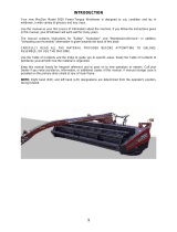
The hitch is the windrowers hydraulic oil reservoir. Before disassembly, raise front of hitch to highest point to
prevent excessive spillage.
IMPORTANT:
Dirt, dust, water and foreign material are the major causes of hydraulic system damage. Take
care to prevent pumps, hoses and fittings becoming contaminated.
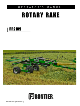
Attach plate & torque arm to pump assembly
a) From the pump assembly to be installed, remove two 1/2 NC bolts which join the hydraulic pump section to
the gearbox section. Do not separate the two sections.
b) From the pump assembly to be removed, remove two bolts (K) and lockwashers (C) to detach plate
(ref. 2)
c) Install plate (ref. 2) to the new pump assembly with bolts (K) and lockwashers (C). Be sure arm (ref. 3) and
chain (ref. 4) are properly attached as shown. Note that arm must engage drawbar on right hand side.
d) Install the two shorter bolts removed in Step a) to secure the two sections of the pump assembly.
e) Install new decal (regarding PTO speed) over the existing decal on left side of tongue, near jack storage
position.
Attach hydraulic hoses
a) Remove plastic plugs from the three hydraulic ports and from the spline bore.
b) Switch hydraulic hoses complete with end fittings from one pump to the other.
c) Install the four plastic plugs in the unit to be returned.
Package pump assembly
Place unit (with hydraulic ports and spline bore properly sealed) in the wood box and return (with
"Authorization for Return" form) to Winnipeg factory for credit.
Remember credit will not be granted if pump is
used, damaged or contaminated.
REF DESCRIPTION
1 PUMP - hydraulic, assembly
2 PLATE - pump
3 ARM - torque
4 CHAIN - 21 link
A BOLT - hex head, 1/2 NC x 1 1/4 inch
B NUT - hex, 1/2 inch NC
C WASHER - lock, 1/2 inch
D BOLT - hex head, 3/8 NC x 1 inch
E WASHER - flat, 13/32 inch ID
F NUT - lock, 3/8 inch NC distorted thread
K BOLT - hex head, 1/2 NC x 1 3/4 inch
Form 46007 5/92
NOTE:
Credit for the returned pump assembly will not be granted if pump is used, damaged or
contaminated.
/