Page is loading ...

Double Windrow Attachment (DWA)
for M1 Series Windrowers
DWA Serial Number 371190 and Later
Setup, Operation, and Parts Manual
215160 Revision B
Original Instruction
The Harvesting Specialists.

This instruction contains the setup procedures, operation instructions, and parts lists for the MacDon Double Windrow
Attachment (DWA) for M1 Series Windrowers.
1031141
Published: February 2020
© 2020 MacDon Industries, Ltd.
The information in this publication is based on the information available and in effect at the time of printing. MacDon
Industries, Ltd. makes no representation or warranty of any kind, whether expressed or implied, with respect to the
information in this publication. MacDon Industries, Ltd. reserves the right to make changes at any time without notice.

Introduction
IMPORTANT:
This manual (MD #215160) applies to Double Windrow Attachment (DWA) serial number 371190 and later, for DWA’s
mounted onto a M1 Series Windrower. If the DWA serial number is prior to 371190 and mounted onto a M1 Series
Windrower, refer to manual MD #214763.
The Double Windrow Attachment (DWA) provides the ability to place two or three windrows of conditioned material close
together. The DWA can be mounted on the following MacDon Windrowers:
• M1170
• M1240
The DWA is for use with the following headers:
• A Series Auger Headers (Non-Grass Seed Only)
• R85 Rotary Disc Headers
• R216 Rotary Disc Headers
IMPORTANT:
The DWA is incompatible with R1 Series Rotary Disc Headers.
When the DWA system is engaged, conditioned crop is deposited onto the side draper and then delivered to the right side
of the windrower. Raising the side delivery disengages the DWA, allowing the crop to be deposited between the
windrower’s wheels.
Carefully read all the material provided before attempting to use the machine.
When setting up the machine or making adjustments, review and follow the recommended machine settings in all relevant
MacDon publications. Failure to do so may compromise machine function and machine life and may result in a hazardous
situation.
MacDon provides warranty for Customers who operate and maintain their equipment as described in this manual. A copy
of the MacDon Industries Limited Warranty Policy, which explains this warranty, should have been provided to you by your
Dealer. Damage resulting from any of the following conditions will void the warranty:
• Accident
• Misuse
• Abuse
• Improper maintenance or neglect
• Abnormal or extraordinary use of the machine
• Failure to use the machine, equipment, component, or part in accordance with the manufacturer’s instructions
NOTE:
Keep your MacDon publications up-to-date. The most current version can be downloaded from our website
(www.macdon.com) or from our Dealer-only site (https://portal.macdon.com) (login required).
The following conventions are used in this document:
• Right and left are determined from the operator’ s position, facing forward with the windrower in cab-forward position.
• Unless otherwise noted, use the standard torque values provided in Chapter 6.1 Torque Specifications, page 105 of this
document.
Call your MacDon Dealer if you need assistance, information, or additional copies of this manual.
This instruction is currently available in English only.
215160 i Revision B

Summary of Changes
At MacDon, we’re continuously making improvements: occasionally these improvements impact product documentation.
The following list provides an account of major changes from the previous version of this document.
Section
Summary of Change
Internal Use
Only
Front cover
Added serial number range to cover. Product Support
Introduction, page i Added the following IMPORTANTS for clarity:
• This manual (MD #215160) applies to Double Windrow
Attachment (DWA) serial number 371190 and later, for DWA’s
mounted onto a M1 Series Windrower. If the DWA serial number
is prior to 371190 and mounted onto a M1 Series Windrower,
refer to manual MD #214763.
• The DWA is incompatible with R1 Series Rotary Disc Headers.
Product Support
Tech Pubs
2.2 Configuring the DWA,
page 20
• Figure 2.3, page 20
Replaced the text “DISC” and “SICKLE” with callouts “D1” and “D2”
to make picture easier to translate.
Tech Pubs
2.3 Parts List – Hardware Bag,
page 21
Added topic for clarity.
Tech Pubs
2.4 Installing the Linkage,
page 22
Removed the following step and associated picture because
hardware used to attach the DWA linkage now shipped in a bag:
• Remove the hardware at locations (A) and (B) that are loosely
installed on the DWA linkage. Retain hardware for attaching
linkage to windrower frame.
UECN 31155
2.4 Installing the Linkage,
page 22
• Step 2, page 22
Added step and associated picture because the clevis is now shipped
attached to the linkage, not the deck.
UECN 31156
2.4 Installing the Linkage,
page 22
• Step 3, page 22
Added step because removal of turnbuckle from shipping
configuration was previously missed.
Tech Pubs
2.4 Installing the Linkage,
page 22
• Step 7, page 23
Added step because hardware is now shipped in a bag, not retained.
UECN 31155
2.4 Installing the Linkage,
page 22
• Step 8, page 23
Revised steps because hardware is now shipped in a bag, not
retained.
UECN 31155
2.4 Installing the Linkage,
page 22
• Step 8, page 23
Added IMPORTANT.
Engineering
2.4 Installing the Linkage,
page 22
• Step
9, page 24
Revised steps because hardware is now shipped in a bag, not
retained.
UECN 31155
215160 ii Revision B

Section
Summary of Change
Internal Use
Only
2.4 Installing the Linkage,
page 22
• Step 11, page 24
Added step and picture to avoid damage to hoses. Tech Pubs
2.4 Installing the Linkage,
page 22
• Step
Added NOTE.
Engineering
2.5 Installing the Deck, page
26
• Step 1, page 26
Added to step because deck motor hoses are now shipped attached
to the motor:
• Remove shipping wire securing deck motor hoses to deck (not
shown).
UECN 31189
2.5 Installing the Deck, page
26
• Step 2, page 26
Revised step and picture because front shipping stands are only
removed after clevis is installed.
Tech Pubs
2.5 Installing the Deck, page
26
Removed step and associated picture that explained how to remove
the clevis that was strapped to the deck, because the clevis is now
shipped to the linkage, not the deck.
UECN 31156
2.5 Installing the Deck, page
26
Removed step and associated picture that explained how to remove
hardware that was shipped attached to the clevis, because the
hardware is now shipped in a bag.
UECN 31156
2.5 Installing the Deck, page
26
• Step 11, page 28
Added step because the clevis hardware is now shipped in a bag.
UECN 31156
2.5 Installing the Deck, page
26
• Step 12, page 29
Revised step and picture as follows:
• UECN 31156: Clevis hardware is now shipped in a bag.
• UECN 31199: Longer bolt MD #136157 replaces one of bolt
MD #136082.
UECN 31156
UECN 31199
2.5 Installing the Deck, page
26
• Step 19, page 30
Revised step and picture because front shipping stands are only
removed after clevis is installed.
Tech Pubs
2.5 Installing the Deck, page
26
• Step 22, page 31
Added instructions for retrieving and installing clevis pins and cotter
pins on turnbuckle.
Tech Pubs
2.6 Connecting the Hydraulics
to an M1170 Windrower,
page 33
Added WARNING:
• To avoid injury or death from unexpected start-up of machine,
always stop the engine and remove the key from the ignition
before leaving the operator’s seat for any reason.
Tech Pubs
2.6 Connecting the Hydraulics
to an M1170 Windrower,
page 33
Changed the following statement from a CAUTION to a WARNING:
• Check to be sure all bystanders have cleared the area.
Tech Pubs
215160 iii Revision B

Section
Summary of Change
Internal Use
Only
2.6 Connecting the Hydraulics
to an M1170 Windrower,
page 33
• Step 6, page 35
Added step to explain where to find parts.
Tech Pubs
2.6 Connecting the Hydraulics
to an M1170 Windrower,
page 33
• Step 7, page 35
Revised step and associated pictures to show new clamp
MD #103738 and bolt MD #184661.
UECN 31194
2.6 Connecting the Hydraulics
to an M1170 Windrower,
page 33
• Step 8, page 36
Added instructions to step for retrieving cable ties from bag shipped
with DWA.
Tech Pubs
2.6 Connecting the Hydraulics
to an M1170 Windrower,
page 33
Removed steps and pictures associated with connecting pressure,
return, and case drain hose to deck motor and routing them through
the tube, because these hoses are now shipped attached to the
motor.
UECN 31189
2.6 Connecting the Hydraulics
to an M1170 Windrower,
page 33
• Step 13, page 37
• Step 14, page 37
Flipped the order of these steps to correct torque sequence.
Tech Pubs
2.6 Connecting the Hydraulics
to an M1170 Windrower,
page 33
• Step 15, page 38 to Step
21, page 38
UECN 31189: Revised steps and made new picture because these
hoses are now shipped attached to the motor.
• UECN 31194: Picture also shows the new clamp and cinch strap.
UECN 31189
UECN 31194
2.6 Connecting the Hydraulics
to an M1170 Windrower,
page 33
• Step 15, page 38
• Step 17, page 38
Added footnote to identify hose according to the part number on
the hose label.
Tech Pubs
2.7 Connecting the Hydraulics
to an M1240 Windrower,
page 39
Added WARNING:
• To avoid injury or death from unexpected start-up of machine,
always stop the engine and remove the key from the ignition
before leaving the operator’s seat for any reason.
Tech Pubs
2.7 Connecting the Hydraulics
to an M1240 Windrower,
page 39
Changed the following statement from a CAUTION to a WARNING:
• Check to be sure all bystanders have cleared the area.
Tech Pubs
2.7 Connecting the Hydraulics
to an M1240 Windrower,
page 39
• Step 6, page 41
Added step to explain where to find parts.
Tech Pubs
215160 iv Revision B

Section
Summary of Change
Internal Use
Only
2.7 Connecting the Hydraulics
to an M1240 Windrower,
page 39
• Step 7, page 41
Revised step and associated pictures to show new clamp
MD #103738 and bolt MD #184661.
UECN 31194
2.7 Connecting the Hydraulics
to an M1240 Windrower,
page 39
• Step 8, page 42
Added instructions to step for retrieving cable ties from bag shipped
with DWA.
Tech Pubs
2.7 Connecting the Hydraulics
to an M1240 Windrower,
page 39
• Step 9, page 42
Removed MD #291237 from the step because that part is not a part
of the DWA.
Tech Pubs
2.7 Connecting the Hydraulics
to an M1240 Windrower,
page 39
• Step 10, page 42
Removed MD #201893 from the step because that part is not a part
of the DWA.
Tech Pubs
2.7 Connecting the Hydraulics
to an M1240 Windrower,
page 39
Removed steps and pictures associated with connecting pressure,
return, and case drain hose to deck motor and routing them through
the tube, because these hoses are now shipped attached to the
motor.
UECN 31189
2.7 Connecting the Hydraulics
to an M1240 Windrower,
page 39
• Step 12, page 43
• Step 13, page 43
Flipped the order of these steps to correct torque sequence.
Tech Pubs
2.7 Connecting the Hydraulics
to an M1240 Windrower,
page 39
• Step 14, page 44 to Step
19, page 45
UECN 31189: Revised steps and made new picture because these
hoses are now shipped attached to the motor.
• UECN 31194: Picture also shows the new clamp and cinch strap.
UECN 31189
UECN 31194
2.7 Connecting the Hydraulics
to an M1240 Windrower,
page 39
• Step 14, page 44
• Step 16, page 44
Added footnote to identify hose according to the part number on
the hose label.
Tech Pubs
2.9 Checking Clearance
between Front Skid and
Draper, page 48
Added topic to avoid draper overheating during initial run. Tech Pubs
2.10 Activating the DWA,
page 49
Revised introductory NOTE as follows to emphasize the ground
speed lever (GSL) will only function if a header ID is present:
• The ground speed lever (GSL) controls for the DWA will only
work when there is a recognized header ID (wired or forced) and
the DWA has been activated for that header type. For more
Product Support
215160 v Revision B

Section
Summary of Change
Internal Use
Only
information on header setup and recognizing the header ID, refer
to your header or windrower operator’s manual.
3.2.2 Disengaging the Deck
Safety Pin, page 54
Added topic. Tech Pubs
3.3 Raising and Lowering the
Deck, page 56
Added introductory NOTE:
• The ground speed lever (GSL) controls for the DWA will only
work when there is a recognized header ID (wired or forced) and
the DWA has been activated for that header type.
Product Support
Added to the NOTE:
• If set up with an R85 or R216 Rotary Disc Header, the DWA deck
will only be in its most forward position when the windrower is
running. The lift cylinder is single-acting and not pressurized
when the windrower is shut off.
Engineering
3.5.2 Adjusting Deck Angle
Relative to the Ground, page
62
• Step 1, page 62
Revised step and associated picture to identify the new longer bolt.
UECN 31199
3.5.2 Adjusting Deck Angle
Relative to the Ground, page
62
• Step 1, page 62
Added NOTE to step for clarity.
Engineering
3.5.2 Adjusting Deck Angle
Relative to the Ground, page
62
• Step 6, page 63
Revised step and associated picture to identify the new longer bolt.
UECN 31199
4.1.3 Adjusting Draper
Tracking, page 72
• Step 1, page 72 to Step 3,
page 72
Added safety steps.
Tech Pubs
4.1.4 Replacing Draper, page
74
• Step 2, page 74
Added safety step:
• Shut down the engine, and remove the key from the ignition.
Tech Pubs
Removing and Reinstalling the
Drive Roller, page 77
• Step 2, page 77
Added safety step:
• Shut down the engine, and remove the key from the ignition.
Tech Pubs
4.1.8 Replacing Draper Roller
Bearing/Seal, page 82
• Step 4, page 82
Added IMPORTANT to step to specify the type of lubricant.
Tech Pubs
5 Repair Parts, page 87
• Added statement about bold text.
Tech Pubs
5.1 Abbreviations, page 88
Added topic.
Tech Pubs
215160 vi Revision B

Section
Summary of Change
Internal Use
Only
5.2 Serial Number Breaks,
page 89
Added topic. Tech Pubs
Removing and Reinstalling the
Idler Roller, page 80
Added safety step:
• Shut down the engine, and remove the key from the ignition.
Tech Pubs
5.3 Deck, Draper, and Rollers,
page 90
Revised the parts list and picture as follows:
• MD #136082: Removed a quantity of one, for a total of three.
• MD #136157: Added a quantity of one, for a total of one.
UECN 31199
5.3 Deck, Draper, and Rollers,
page 90
Added as a serviceable part of MD #135888:
• MD #135868
Tech Pubs
5.3 Deck, Draper, and Rollers,
page 90
Added as a serviceable part of MD #135821:
• MD #30971
• MD #135868
Tech Pubs
5.3 Deck, Draper, and Rollers,
page 90
Added as a serviceable part of MD #135788:
• MD #30971
• MD #135868
Tech Pubs
5.4 Linkage and Deck Support,
page 96
Revised the parts list and picture as follows:
• MD #136135: Removed a quantity of one, for a total of none.
• MD #108172: Added a quantity of one, for a total of one.
• MD #135799: Added a quantity of one, for a total of 12.
• MD #184711: Added a quantity of one, for a total of 6.
UECN 31153
5.4 Linkage and Deck Support,
page 96
Revised the parts list and picture as follows:
• MD #30627: Removed a quantity of one, for a total of one.
• MD #184661: Added a quantity of one, for a total of one.
UECN 31194
5.5 Hydraulic Hoses, page 100 Revised the parts list and picture as follows:
• MD #176883: Replaces MD #176680
• MD #135443: Added a quantity of two, for a total of 6.
UECN 31194
5.5 Hydraulic Hoses, page 100 Added as a serviceable part of MD #135784:
• MD #135867
Tech Pubs
5.5 Hydraulic Hoses, page 100
Revised serviceable part MD #135386 as follows:
• Added “(Faster)” to the description of MD #135386 and
associated footnote.
• Added serviceable part MD #111978.
ECN 58441
215160 vii Revision B


Serial Number Location
XXXXXX-XX
XX
1015438
A
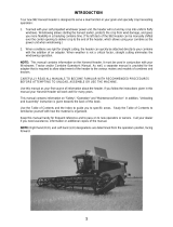
Figure 1: Serial Number Location
Record the serial number of the Double Windrow Attachment
(DWA) in the space provided.
DWA serial number: __________________________
The serial number plate is located on the deck (A).
215160 ix Revision B


215160 xi Revision B
Introduction ................................................................................................................................................i
Summary of Changes....................................................................................................................................ii
Serial Number Location ............................................................................................................................... ix
Chapter 1: Safety .................................................................... .................................................................... 1
1.1 Safety Alert Symbols ............................................................................................................................... 1
1.2 Signal Words ......................................................................................................................................... 2
1.3 General Safety ....................................................................................................................................... 3
1.4 Maintenance Safety ................................................................................................................................ 5
1.5 Hydraulic Safety ..................................................................................................................................... 6
1.6 Tire Safety............................................................................................................................................. 7
1.7 Battery Safety ........................................................................................................................................8
1.8 Welding Precaution ................................................................................................................................ 9
1.9 Engine Safety....................................................................................................................................... 13
1.9.1 High-Pressure Rail ........................................................................................................................ 13
1.9.2 Engine Electronics ........................................................................................................................ 14
1.10 Safety Signs ....................................................................................................................................... 15
1.10.1 Installing Safety Decals ................................................................................................................ 15
1.11 Safety Sign Decals ...............................................................................................................................16
1.12 Safety Decal Locations .........................................................................................................................18
Chapter 2: Assembly/Setup Instructions.................................................................. ............................... 19
2.1 Raising the Right Stairs .......................................................................................................................... 19
2.2 Configuring the DWA ............................................................................................................................20
2.3 Parts List – Hardware Bag ...................................................................................................................... 21
2.4 Installing the Linkage............................................................................................................................. 22
2.5 Installing the Deck ................................................................................................................................ 26
2.6 Connecting the Hydraulics to an M1170 Windrower ................................................................................... 33
2.7 Connecting the Hydraulics to an M1240 Windrower ................................................................................... 39
2.8 Connecting the Proximity Sensor............................................................................................................. 46
2.9 Checking Clearance between Front Skid and Draper ................................................................................... 48
2.10 Activating the DWA............................................................................................................................. 49
2.10.1 Setting One-Touch-Return Buttons (A, B, C) .................................................................................... 50
2.10.2 Setting Draper Pressure Alarm...................................................................................................... 51
Chapter 3: Operation...................... ...................................................................................... .................... 53
3.1 Operational Safety................................................................................................................................ 53
3.2 Engaging and Disengaging the Deck Safety Pin........................................................................................... 54
3.2.1 Engaging the Deck Safety Pin ......................................................................................................... 54
3.2.2 Disengaging the Deck Safety Pin ..................................................................................................... 54
3.3 Raising and Lowering the Deck................................................................................................................ 56
TABLE OF CONTENTS

215160 xii Revision B
3.3.1 Adjusting the Deck Lift Speed......................................................................................................... 57
3.3.2 Adjusting the Proximity Sensor ....................................................................................................... 58
3.4 Setting Draper Speed ............................................................................................................................ 59
3.5 Adjusting Deck Angle ............................................................................................................................ 61
3.5.1 Adjusting Deck Angle Relative to the Drive Tire .................................................................................61
3.5.2 Adjusting Deck Angle Relative to the Ground .................................................................................... 62
3.6 Raising the Deck Height ......................................................................................................................... 64
3.7 Positioning the Conditioner Forming Shield ............................................................................................... 66
3.8 Positioning the Conditioner Rolls............................................................................................................. 68
3.9 Operating Recommendations ................................................................................................................. 69
3.9.1 Operating with an A Series Auger Header.........................................................................................69
3.9.2 Operating with an R85 or R216 Rotary Disc Header............................................................................ 69
Chapter 4: Maintenance and Servicing.................................................................................................... 71
4.1 Draper Maintenance ............................................................................................................................. 71
4.1.1 Adjusting Draper Tension .............................................................................................................. 71
4.1.2 Checking Draper Tracking ..............................................................................................................71
4.1.3 Adjusting Draper Tracking.............................................................................................................. 72
4.1.4 Replacing Draper ......................................................................................................................... 74
4.1.5 Adjusting Front Skid .....................................................................................................................75
4.1.6 Adjusting Rear Deflector ............................................................................................................... 76
4.1.7 Maintaining Draper Rollers ............................................................................................................ 77
Removing and Reinstalling the Drive Roller ..................................................................................... 77
Removing and Reinstalling the Idler Roller ...................................................................................... 80
4.1.8 Replacing Draper Roller Bearing/Seal............................................................................................... 82
4.2 Lubrication .......................................................................................................................................... 83
4.3 Hydraulic Schematic – DWA on M1170..................................................................................................... 84
4.4 Hydraulic Schematic – DWA on M1240..................................................................................................... 85
4.5 Double Windrow Attachment Proximity Switch.......................................................................................... 86
Chapter 5: Repair Parts .......................................................................................... .................................. 87
5.1 Abbreviations ......................................................................................................................................88
5.2 Serial Number Breaks ............................................................................................................................ 89
5.3 Deck, Draper, and Rollers .......................................................................................................................90
5.4 Linkage and Deck Support ......................................................................................................................96
5.5 Hydraulic Hoses ................................................................................................................................. 100
5.6 Decals and Reflectors .......................................................................................................................... 102
Chapter 6: Reference ...................... ...................................................................................... .................. 105
6.1 Torque Specifications .......................................................................................................................... 105
6.1.1 SAE Bolt Torque Specifications ..................................................................................................... 105
6.1.2 Metric Bolt Specifications ............................................................................................................ 107
6.1.3 Metric Bolt Specifications Bolting into Cast Aluminum ...................................................................... 109
TABLE OF CONTENTS

215160 xiii Revision B
6.1.4 Flare-Type Hydraulic Fittings ........................................................................................................ 110
6.1.5 O-Ring Boss Hydraulic Fittings – Adjustable .................................................................................... 111
6.1.6 O-Ring Boss Hydraulic Fittings – Non-Adjustable.............................................................................. 113
6.1.7 O-Ring Face Seal Hydraulic Fittings................................................................................................ 114
6.1.8 Tapered Pipe Thread Fittings........................................................................................................ 115
6.2 Conversion Chart................................................................................................................................ 116
Index.................................................................. ...................................................................................... 117
Predelivery Checklist .............................................................................................................................. 121
Recommended Lubricants...................................................................................................................... 123
TABLE OF CONTENTS


215160 1 Revision B
Chapter 1: Safety
1.1 Safety Alert Symbols
1000915
Figure 1.1: Safety Symbol
This safety alert symbol indicates important safety messages in
this manual and on safety signs on the machine.
This symbol means:
• ATTENTION!
• BECOME ALERT!
• YOUR SAFETY IS INVOLVED!
Carefully read and follow the safety message accompanying this
symbol.
Why is safety important to you?
• Accidents disable and kill
• Accidents cost
• Accidents can be avoided

215160 2 Revision B
1.2 Signal Words
Three signal words, DANGER, WARNING, and CAUTION, are used to alert you to hazardous situations. Two signal words,
IMPORTANT and NOTE, identify non-safety related information. Signal words are selected using the following guidelines:
DANGER
Indicates an imminently hazardous situation that, if not avoided, will result in death or serious injury.
WARNING
Indicates a potentially hazardous situation that, if not avoided, could result in death or serious injury. It may also be
used to alert against unsafe practices.
CAUTION
Indicates a potentially hazardous situation that, if not avoided, may result in minor or moderate injury. It may be used
to alert against unsafe practices.
IMPORTANT:
Indicates a situation that, if not avoided, could result in a malfunction or damage to the machine.
NOTE:
Provides additional information or advice.
SAFETY

215160 3 Revision B
1.3 General Safety
1000004
Figure 1.2: Safety Equipment
CAUTION
The following general farm safety precautions should be part of
your operating procedure for all types of machinery.
Protect yourself when assembling, operating, and servicing
machinery, wear all protective clothing and personal safety
devices that could be necessary for the job at hand. Do NOT
take chances. You may need the following:
• Hard hat
• Protective footwear with slip-resistant soles
• Protective glasses or goggles
• Heavy gloves
• Wet weather gear
• Respirator or filter mask
1000005
Figure 1.3: Safety Equipment
• Be aware that exposure to loud noises can cause hearing
impairment or loss. Wear suitable hearing protection devices
such as earmuffs or earplugs to help protect against loud
noises.
1010391
Figure 1.4: Safety Equipment
• Provide a first aid kit in case of emergencies.
• Keep a properly maintained fire extinguisher on the machine.
Be familiar with its proper use.
• Keep young children away from machinery at all times.
• Be aware that accidents often happen when the Operator is
tired or in a hurry. Take time to consider safest way. NEVER
ignore warning signs of fatigue.
SAFETY

215160 4 Revision B
1000007
Figure 1.5: Safety around Equipment
• Wear close-fitting clothing and cover long hair. NEVER wear
dangling items such as scarves or bracelets.
• Keep all shields in place. NEVER alter or remove safety
equipment. Make sure driveline guards can rotate
independently of shaft and can telescope freely.
• Use only service and repair parts made or approved by
equipment manufacturer. Substituted parts may not meet
strength, design, or safety requirements.
1000008
Figure 1.6: Safety around Equipment
• Keep hands, feet, clothing, and hair away from moving parts.
NEVER attempt to clear obstructions or objects from a
machine while the engine is running.
• Do NOT modify the machine. Unauthorized modifications
may impair machine function and/or safety. It may also
shorten the machine’s life.
• To avoid injury or death from unexpected startup of the
machine, ALWAYS stop the engine and remove the key from
the ignition before leaving the operator’s seat for any reason.
1000009
Figure 1.7: Safety around Equipment
• Keep service area clean and dry. Wet and/or oily floors are
slippery. Wet spots can be dangerous when working with
electrical equipment. Be sure all electrical outlets and tools
are properly grounded.
• Keep work area well lit.
• Keep machinery clean. Straw and chaff on a hot engine are
fire hazards. Do NOT allow oil or grease to accumulate on
service platforms, ladders, or controls. Clean machines before
storage.
• NEVER use gasoline, naphtha, or any volatile material for
cleaning purposes. These materials may be toxic and/or
flammable.
• When storing machinery, cover sharp or extending
components to prevent injury from accidental contact.
SAFETY
/