Page is loading ...

1
INTRODUCTION
This Manual contains information on the adapter which is required to allow attachment of the MacDon Model
962 and 972 Harvest Header to the various models of combines (see list on cover).
NOTE: This supplement does not provide all the information required to operate the header. It must be used
in conjunction with your Harvest Header and Combine Operator’s Manuals.
CAREFULLY READ ALL MANUALS TO BECOME FAMILIAR WITH RECOMMENDED PROCEDURES
BEFORE ATTEMPTING TO UNLOAD, ASSEMBLE OR USE THE MACHINE.
This manual is divided into sections on: Safety, Attaching and Detaching the Header, Operation and
Maintenance/Service. In addition, Assembly and Adapter Mounting Instructions for each type of combine are
found at the back of this book.
Use the Table of Contents and the Index to guide you to specific areas. Study the Table of Contents to
familiarize yourself with how the material is organized.
Keep this manual handy for frequent reference and to pass on to new operators or owners. Call your dealer
if you need assistance, information or additional copies of the manual.
NOTE: Right hand (R/H), and Left hand (L/H) designations are determined from the operators position, facing
forward.

2
TABLE OF CONTENTS
INTRODUCTION ........................................................................................................................................1
SPECIFICATIONS......................................................................................................................................3
SERIAL NUMBER LOCATION ...................................................................................................................3
SAFETY
Safety Alert Symbol................................................................................................................................4
Signal Words .........................................................................................................................................4
Safety Signs...........................................................................................................................................5
HEADER ATTACHING & DETACHING
Attaching Header to Combine and Adapter........................................................................................6-9
Detaching Header from Combine and Adapter...............................................................................10,11
Detaching Header and Adapter from Combine....................................................................................12
Attaching Header and Adapter to Combine.........................................................................................13
OPERATION
Break-In Period....................................................................................................................................14
Draper Speed Control..........................................................................................................................14
Header Flotation ..................................................................................................................................15
Header Levelling..................................................................................................................................16
Header Angle.......................................................................................................................................16
Widening the Delivery Opening ...........................................................................................................17
Windrowing with the Combine (972 Feed Pan Clearance Adjustment)...............................................17
MAINTENANCE/SERVICE
Service Procedures..............................................................................................................................18
Recommended Lubricants...................................................................................................................18
Enclosed Drive Lubricant Capacities...................................................................................................18
Sealed Bearing Installation ..................................................................................................................19
Greasing the Adapter......................................................................................................................19,20
Hydraulic System
Hydraulic System Safety...................................................................................................................21
Hoses and Lines ...............................................................................................................................21
Hydraulic Schematic .........................................................................................................................21
Hydraulic Oil......................................................................................................................................22
Hydraulic Oil Filter.............................................................................................................................22
Flow Control Relief Pressure ............................................................................................................23
Gearbox Lubrication.............................................................................................................................23
Retracting Tine Drum...........................................................................................................................24
Maintenance Schedule ........................................................................................................................25
Maintenance Record............................................................................................................................26
TROUBLESHOOTING........................................................................................................................27, 28
ATTACHMENTS.......................................................................................................................................29
ASSEMBLY
962 Header Completion Parts .............................................................................................................30
Header Side Drapers & Feeder Deck..................................................................................................31
Feed Draper.........................................................................................................................................32
Center Link...........................................................................................................................................33
Position Retracting Tine Drum.............................................................................................................34
Electrical ..............................................................................................................................................35
Adjustments and Checks.....................................................................................................................36
ADAPTER MOUNTING INSTRUCTIONS
John Deere .....................................................................................................................................37-41
Case IH...........................................................................................................................................42-47
Gleaner...........................................................................................................................................48-54
New Holland....................................................................................................................................55-61
Cat Lexion.......................................................................................................................................62-67
Attaching Adapter to Header (without combine)..................................................................................68
Float Spring Removal or Installation..............................................................................................69, 70
Float Limiter Installation: John Deere 50 Series, Contour Master & New Holland TR Combines .......71
INDEX.......................................................................................................................................................72

3
SPECIFICATIONS
FEED DRAPER DRIVE Hydraulic: Pump driven from right side of feeder house, reversible
with combine feeder chain
FEED DRAPER SPEED 522 to 652 feet/min. (159 to 199 metres/min.) varies with combine
FEED DRAPER MATERIAL Self-tracking rubber coated polyester fabric with rubber slats
FEED DRAPER WIDTH:
John Deere & New Holland TX, Cat Lexion 460, 465, 480 & 485 ......................55.9 inches (1420 mm)
Case 80 & 88 Series, Cat Lexion 450, 470 & 475 ..............................................45.5 inches (1155 mm)
Case 60 & 66 Series, Gleaner, & New Holland TR...............................................38.4 inches (975 mm)
RETRACTING TINE DRUM DRIVE Hydraulic: Pump driven from right side of feeder house, reversible
with combine feeder chain
RETRACTING TINE DRUM SPEED 173 to 216 RPM, varies with combine
RETRACTING TINE DRUM DIA.
John Deere & New Holland TX, Cat Lexion 460, 465, 480 & 485 ...........................12 inches (300 mm)
Case, Gleaner, New Holland TR & Cat Lexion 450, 470 & 475..................................11” (280 mm) with
1 ¼” (32 mm) flighting on ends
HEADER SIDE DRAPER DRIVE Hydraulic: Pump driven from right side of feeder house
HEADER SICKLE DRIVE Mechanical: Driveline from left side of feeder house
HEADER FLOTATION 7 inches (175 mm) vertical and 4.5° lateral
HEADER REEL DRIVE Hydraulic from combine oil supply
SERIAL NUMBER LOCATION
Record the serial number in the space provided.
872 Combine Adapter:
Plate (A) is located on left side of adapter
frame.
NOTE: When ordering parts and service, be sure to give your dealer the complete and proper serial number.
COMBINE ADAPTER SERIAL PLATE
A

4
SAFETY
SAFETY ALERT SYMBOL
This safety alert symbol indicates important safety messages in this manual and
on safety signs on the header.
This symbol means:
ATTENTION !
BECOME ALERT !
YOUR SAFETY IS INVOLVED !
Carefully read and follow the safety message accompanying this symbol.
Why is SAFETY important to you?
· ACCIDENTS DISABLE AND KILL
3 BIG REASONS · ACCIDENTS COST
· ACCIDENTS CAN BE AVOIDED
SIGNAL WORDS
Note the use of the signal words DANGER, WARNING, and CAUTION with safety messages. The appropriate
signal word for each message has been selected using the following guidelines:
DANGER – Indicates an imminently hazardous situation that, if not avoided, will result in death or
serious injury.
WARNING – Indicates a potentially hazardous situation that, if not avoided, could result in death
or serious injury. It is also used to alert against unsafe practices.
CAUTION – Indicates a potentially hazardous situation that, if not avoided, may result in minor or
moderate injury. It is also used as a reminder of good safety practices.

5
SAFETY
SAFETY SIGNS
• The safety signs below appear on the combine adapter.
• Keep safety signs clean and legible at all times
• Replace safety signs that are missing or become illegible.
• If original parts on which a safety sign was installed are replaced, be sure the repair part also bears the
current safety sign.
• Safety signs are available from your Dealer Parts Department.
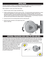
To install safety signs:
1. Be sure the installation area is clean and dry.
2. Decide on the exact location before you remove the decal backing paper.
3. Remove the smaller portion of the split backing paper.
4. Place the sign in position and slowly peel back the remaining paper, smoothing the sign as it is applied.
5. Small air pockets can be smoothed out or pricked with a pin.
Rest header on ground or engage mechanical
locks before going under unit.

6
CONNECT TOP LINK BEFORE LIFTING
HEADER ATTACHING & DETACHING
ATTACHING HEADER TO COMBINE AND ADAPTER
1. Attach adapter to combine feeder housing. See
"Adapter Mounting Instruction" at back of book.
NOTE: If header has been previously attached
to windrower, remove linkage supports from
header lower legs. Connector shaft on header
back tube may remain installed.
2. Choose an area that is as level as possible,
and place supports (A) at both ends of
cutterbar. For 962 Headers use 6" (150 mm)
blocks. For 972 Headers use 2x4 (40 mm)
blocks.
3. For 962 headers with gauge wheels, block both
wheels front and rear, and be sure gauge
wheel pins are in stand position (L), both sides,
to support rear of header.
For 972 headers and 962 headers without
gauge wheels, be sure header stand (B) is
secure in the down position. For 962 Headers
only, place a 4 inch (100 mm) block under
stand.
CAUTION: Be sure area is clear of
bystanders before starting engine.
4. Slowly drive combine forward, aligning float leaf
springs under header legs, until top link can be
connected. Connect top link (C).
NOTE: For headers with hydraulic top link, see
instruction in “Unloading & Assembly” section.
CAUTION: Always connect top link
before raising header.
IMPORTANT: Take care not to crush hydraulic
hoses when driving into header.
IMPORTANT: For 972 Headers, when driving
into header, align notches in adapter feed pan
with retainers welded to cutterbar. Ensure that
pan goes under the retainer and on top of
cutterbar. The feeder house can be raised to
lower the front edge of the pan, and vice versa.
In soft ground conditions, a length of 2x4 under
the pan will prevent scooping dirt
5. Raise adapter slowly, making sure float leaf
springs engage in header legs. Continue to lift
until header is fully raised. Stop engine and
remove key.
DANGER: To avoid bodily injury
from fall of raised header, engage
header lift cylinder stops when
working on or around raised header. See your
Combine Operator’s Manual for details.
BLOCK CUTTERBAR
GAUGE WHEELS - 962 HEADER STAND - 972
B

7
HEADER ATTACHING & DETACHING
ATTACHING HEADER TO COMBINE AND ADAPTER
(continued)
6. Remove ¾ x 7 ½” bolt and lock nut from
storage position (J) (or, on first use, from
shipping position [G]) and install to lock adapter
to header at (H). Move clevis pin from float
lockout position (G) to storage position (J).
Install split ring to capture clevis pin.
NOTE: It may be necessary to rock header by
lifting at divider to properly position float frame
at header leg joint.
Repeat at other leg.
7. Install sickle driveline on combine feeder house
shaft. Ensure driveline locking mechanism
engages. See your combine Operator's
Manual.
DANGER: Entanglement with
rotating driveline will cause
serious personal injury or death.
Keep all driveline shields in place.
Close all hinged covers.
BOLT ADAPTER TO HEADER & MOVE
PIN FROM FLOAT LOCKOUT TO STORAGE
ATTACH DRIVELINE

8
HEADER ATTACHING & DETACHING
ATTACHING HEADER TO COMBINE AND ADAPTER
(continued)
8. Make the hydraulic line connections:
Reel drive pressure and return lines: Connect
two hoses between header and combine.
Reel lift line: Connect one hose between
header and combine.
Draper drive pressure and return lines:
Connect two hoses between header and
adapter.
NOTE: As an aid in connecting hydraulics, the
following colour coding has been used:
ORANGE - Draper Drive Pressure
BLUE - Draper Drive Return
YELLOW - Reel Drive Return
Reel fore-aft lines (if equipped): Connect two
hoses between header and combine.
9. Connect wiring harness between header and
combine. NOTE: A harness adapter is supplied
with adapter completion package.
10. For 962 headers with gauge wheels, remove
pins at gauge wheels and place in field position
(F). See “Cutting Height” in Header Operator’s
Manual to choose between alternate field
positions. (For headers with gauge
wheel/transport option, gauge wheel support is
not exactly as illustrated. See decal at support.)
NOTE: Rotate pin to align roll pin with key slot
for removal and installation. Roll pin locks
inside to secure the position.
11. For 972 headers and 962 headers without
gauge wheels, raise header stand to storage
position (G).
12. For 972 Headers, for initial setting, set header
at flattest angle (shortest top link length) and
float header up. Ensure that feed pan is as far
forward as possible and tighten pan hardware.
STEPS 13 to 16 ARE FOR 962 HEADERS ONLY.
13. Place 6" (150 mm) block under front of adapter
feeder pan. Ensure all feed pan-to-cutterbar
anchors are removed or turned sideways to
prevent damage to anchors when cutterbar is
lowered. Adjust feed pan fully forward for initial
setting. (See next page.)
14. Disengage header lift cylinder stops and slowly
lower header until adapter feed pan rests on
block, and cutterbar rests on feed pan.
962 GAUGE WHEELS - FIELD POSITION
HEADER STAND - STORAGE POSITION
G

9
HEADER ATTACHING & DETACHING
ATTACHING HEADER TO COMBINE AND ADAPTER
(continued)
15. Install anchors to clamp feed pan to cutterbar
as shown.
16. Check for 0 to 5 mm (3/16 inch) clearance
between front of adapter feed pan and
cutterbar. Adjust clearance as follows:
a. Raise the header. Stop engine and remove
key.
DANGER: To avoid bodily injury
from fall of raised header, engage
header lift cylinder stops when
working on or around raised
header. See your Combine Operator’s Manual
for details.
b.
• Loosen bolts (F) and (G).
• Adjust feed pan clearance to cutterbar to 0 to
5 mm (3/16 inch).
• Tighten bolts (F) and (G).
• Remove all blocks, disengage header lift
cylinder stops and lower header to ground.
• Ensure that outside anchors (E) are installed
as shown, with rubber seal (J) under top plate
of anchor.
SIDE VIEW
ADJUST FEED PAN - 962 HEADER
0 to 5mm
F
E J
G

10
HEADER ATTACHING & DETACHING
DETACHING HEADER FROM COMBINE AND ADAPTER
Using this procedure, adapter will remain attached
to the combine. This would be appropriate when
header is to be used as a windrower. Instructions
for detaching both header and adapter from
combine are given on page 12.
1. Choose a level area. Lower the reel and raise
the header. Stop engine and remove key.
DANGER: To avoid bodily injury from
fall of raised header, engage header
lift cylinder stops when working on
or around raised header. See your Combine
Operator’s Manual for details.
DANGER: Wait for all movement to
stop. A rotating driveline can cause
entanglement resulting in serious
personal injury or death.
2. Disconnect driveline from feeder house shaft
and store at bracket (A) on header left leg.
3. Disconnect hydraulic lines:
- Reel lift between header and combine.
- Reel drive pressure and reel return between
header and combine.
- Draper return (blue) and draper drive pressure
(orange) between adapter and header.
- Reel fore-aft hoses between header and
combine (if equipped).
IMPORTANT: Couple or cap all lines to prevent
hydraulic system contamination except as noted
in Warning below. Be sure header stored hoses
and combine stored hoses are not entangled.
WARNING: For headers with
hydraulic reel fore-aft, never connect
the fore-aft couplers to each other.
This would complete the circuit and allow the
reel to creep forward in transport, resulting in
instability.
4. Disconnect wiring harness between header and
combine.
5. Remove split ring and clevis pin from storage
position (E) and install in float lockout position
(C). Remove ¾ X 7 ½” bolt and lock nut from
adapter lock position (B) and place in storage
position (E). Repeat at other leg.
6. Remove plastic wear strip from under adapter
pan, if equipped. Leave wear strip attached to
clips on cutterbar.
STEPS 7 TO 12 ARE FOR 962 HEADERS ONLY.
FOR 972 HEADERS, GO TO STEP 13.
7. Set 6" (150 mm) blocks under the adapter
feeder pan.
8. Disengage header lift cylinder stops and lower
header so feeder pan rests on blocks.
9. Loosen and rotate cutterbar anchors (D) away
from cutterbar.
INSTALL PIN IN FLOAT LOCKOUT &
ENGAGE FLOAT LOCK-OUT AND
MOVE BOLT TO STORAGE POSITION
STORE DRIVELINE
A
RELEASE CUTTERBAR ANCHORS –
962 HEADERS
D

11
962 GAUGE WHEELS - STAND POSITION
HEADER ATTACHING & DETACHING
DETACHING HEADER FROM COMBINE AND ADAPTER
(continued)
10. Raise header and engage header lift cylinder
stops.
11. Move 6" (150 mm) blocks from under adapter
feeder pan to the outside, about 18" (450 mm)
from each end of header.
12. For 962 headers with gauge wheels, remove
pins at gauge wheels and place in stand
position (B). Block both gauge wheels.
For 962 headers without gauge wheels, lower
header stand and place a 4 inch (100 mm)
block beneath stand.
13. For 972 Headers, lower header stand (E).
Place a 2x4 under stand only if required for
stability on soft ground. Place 2x4’s (40 mm
blocks) under cutterbar, about 18" (450 mm)
from each end of header.
14. Disengage header lift cylinder stops and lower
header onto blocks. Lower adapter until top link
is loose. Detach top link (F).
15. Lower adapter until float leaf springs are clear
of header legs and slowly back away from
header.
DISCONNECT TOP LINK
HEADER STAND - LOWERED
E

12
HEADER ATTACHING & DETACHING
DETACHING HEADER AND ADAPTER FROM COMBINE
Using this procedure, adapter will remain attached to
the header. This would be appropriate when detaching
header for transport. Instructions for detaching header
only from adapter and combine are given on page 10.
1. Choose a level area. Lower the reel and raise the
header. Stop engine and remove key.
DANGER: To avoid bodily injury from
fall of raised header, engage header lift
cylinder stops when working on or
around raised header. See your
Combine Operator’s Manual for details.
2. Remove split ring and clevis pin from storage
position (A) and install in float lockout position (B).
Repeat at other leg. Note that bolt in adapter lock
position (C) remains in place.
3. Disconnect hydraulic lines between header and
combine:
- Reel drive pressure line.
- Reel drive return line.
- Reel lift line.
- Reel fore-aft lines (if equipped).
NOTE: For units with hydraulic center link, before
disconnecting cylinder hoses, turn off oil flow at shut-
off valve. This allows easier reattachment of couplers
at combine. Remember to restore oil flow at shut-off
valve before next use.
IMPORTANT: Couple or cap all lines to prevent hydraulic system contamination except as noted in Warning
below. Be sure header stored hoses and combine stored hoses are not entangled.
WARNING: For headers with hydraulic reel fore-aft, never connect the fore-aft couplers to
each other. This would complete the circuit and allow the reel to creep forward in transport,
resulting in instability.
4. Disconnect wiring harness between header and
combine.
DANGER: Wait for all movement to stop
before approaching driveline. A rotating
driveline can cause entanglement
resulting in serious personal injury or
death.
5. Disconnect driveline from combine feeder house
output shaft and store at header left leg.
6. Disconnect pump from combine feeder house
output shaft and store on adapter. See Mounting
Instruction for your make of combine at back of
book.
NOTE: Wear gloves when handling pump.
7. Disengage the header lock system. See Mounting
Instruction for your make of combine at back of book.
8. Disengage header lift cylinder stops, start engine and lower header to ground.
9. Slowly back combine away from header.
DISCONNECT AND STORE DRIVELINE
INSTALL PIN IN LOCKOUT POSITION

13
HEADER ATTACHING & DETACHING
ATTACHING HEADER AND ADAPTER TO COMBINE
1. If applicable, block both gauge wheels front
and rear (B).
NOTE: Choose an area that is as level as
possible.
CAUTION: Be sure area is clear of
bystanders before starting engine.
2. Drive combine slowly forward and engage
feeder house lifting device in adapter top cross
member. See Mounting Instruction for your
make of combine at back of book for details.
3. Raise header, stop engine and remove key.
DANGER: To avoid bodily injury from
fall of raised header, engage header
lift cylinder stops when working on
or around raised header. See your Combine
Operator’s Manual for details.
4. Connect feeder house lock system at bottom of
adapter. See Mounting Instruction for your
make of combine at back of book.
5. Install sickle driveline on L/H feeder house
output shaft. Ensure driveline locking
mechanism engages. See your combine
Operator’s Manual.
DANGER: Entanglement with
rotating driveline will cause serious
personal injury or death. Keep all
driveline shields in place.
6. Connect hydraulic lines between header and
combine:
- Reel drive pressure line.
- Reel drive return line.
- Reel lift line.
- Reel fore-aft lines (if equipped).
7. Connect wiring harness between header and
combine.
8. Remove split ring and clevis pin from float
lockout position (A) and install in storage hole
(C). Repeat at other leg.
9. Install pump on R/H feeder house output shaft.
See Mounting Instruction for your make of
combine at back of book.
NOTE: Wear gloves when handling pump.
10. Disengage header lift cylinder stops and lower
header.
REMOVE PIN FROM FLOAT LOCKOUT
BLOCK GAUGE WHEELS

14
OPERATION
BREAK-IN PERIOD
1. Run drapers slowly for 5 minutes to fill hydraulic
lines, then check oil level at (A). Maintain level
between LOW and FULL when oil is cold.
NOTE: Breather screw on cap (A) has been
tightened for shipping. Loosen screw before
operating adapter.
NOTE: When ambient temperatures are above
35º C (95º F), maintain oil level in the low portion
of the range to prevent overflow at breather under
operating temperatures.
2. Change the hydraulic oil filter (D) on combine
adapter after 50 hours operation and every 250
hours thereafter.
3. Change gearbox oil after 50 hours operation and
every 1000 hours or 3 years thereafter.
See "Break-In Period" in Header Operator's Manual for further information on break-in maintenance.
DRAPER SPEED CONTROL
Speed of the header drapers is adjusted at the flow control on the combine adapter. Rotate flow control knob
(C) to a number suited to the crop. The higher the number, the faster the draper speed. The settings in the
chart are recommended for optimum feeding capacity.
NOTE: If sufficient draper speed cannot be achieved, a possible cause is low relief pressure. See "Flow
Control Relief Pressure" in Maintenance/Service section.
Needle Valve: When laying a windrow, turn needle valve control (B) fully
open to stop flow to the feed draper
and drum.
NOTE: Valve must be fully open to prevent rotation of feed draper and
drum when oil is cold. It may also be necessary to secure drum to
prevent rotation.
For a complete list of steps to convert to windrowing mode, see “End
Delivery” in the Operation section of your Header Operator’s Manual.
When straight cutting and experiencing plugging at the rear of the
feeder deck, turn control (B) to slow feed draper and drum.
NOTE: Slowing feed draper and drum too much will cause feeding
problems. Turn needle valve control (B) in 1/16 turn increments.
CHECK HYDRAULIC OIL LEVEL
CHANGE OIL FILTER & GEARBOX OIL
A
D
DRAPER SPEED CONTROL
C
B
CROP
DIAL
NO.
Barley 3
Beans, Edible 4
Canola 3
Flax 5
Lentils 3
Milo 3
Oats 3
Peas 3
Rice 5
Safflowers 4
Soybeans 5
Sunflowers 4
Wheat 3

15
OPERATION
HEADER FLOTATION
IMPORTANT:
To avoid:
- frequent breakage of sickle components
- scooping soil
- soil build-up at cutterbar in wet conditions,
set header float as light as possible without
causing excessive bouncing.
To check header float:
1. Raise feeder house and engage lift cylinder
stops.
2. Be sure float lock out pins are removed from
position (C).
3. Disengage lift cylinder stops and lower header
so the cutterbar is 1 to 6 inches (25 to 150 mm)
above the ground.
NOTE: When cutterbar is in the range from 0 to 16
inches (400 mm) off ground, float arm should
touch or be within ¼ inch (6 mm) of angle at (A). If
gap at (A) is greater than ¼ inch, float is set too
light, causing the header to float up.
NOTE: Header gets lighter and gap at (A)
increases when steepening header angle. Adjust
float after changing header angle or reel fore-aft
position. For best float, gap at (A) should never
exceed ¼ inch (6 mm).
4. With cutterbar 1 to 6 inches (25 to 150 mm)
above the ground, grasp the crop divider rod
and lift up. Under normal conditions it should
require 50 to 70 lbs. force (220 to 310 N) to lift
cutterbar off ground at either end. If adjustment
is required, proceed as follows:
To adjust header float:
1. Raise feeder house and engage lift cylinder
stops.
2. Tighten bolts (B) at both sides of adapter to
increase float (which makes header lighter
when lowered to ground).
Loosen bolts to decrease float (which makes
header heavier when lowered).
IMPORTANT: For 21 ft. 972 headers only. If
header still has excess float with float
adjustment bolt fully backed off, it may be
necessary to remove the 3
rd
leaf spring from
the top on both sides of the adapter to provide
proper floatation. See Unloading and Assembly
section for removal instructions.
FLOAT ADJUSTMENT

16
OPERATION
HEADER LEVELLING
Adjust header levelling with header at the flattest angle.
See Header Angle, below.
1. With header on level ground, lower header so
cutterbar is 2 to 4 inches (50 to 100 mm) off the
ground.
2. Check level of header by measuring cutterbar to
ground at both ends.
3. To lower cutterbar on one end, remove a shim (C)
from between rubber pads (D) and angle (E).
Adjust shim quantity side to side, placing from 0 to
2 shims to level header. To add or remove a shim:
• Lower cutterbar to ground and continue lowering
feeder house so gap at (A) increases.
• Remove nut (F) and add or remove shim(s) as
required.
• Reassemble, maintaining 1/8 inch (3 mm) between
angle and float support as shown.
HEADER ANGLE
The header (or guard) angle can be adjusted from
15° to 20° below horizontal. (Actual angle may vary with
combine set-up.)
See Combine Operator’s Manual for header levelling
and additional header angle adjustments.
IMPORTANT: The flat header angle (15°) is
recommended for normal conditions. A flatter header
angle reduces sickle section breakage and reduces soil
scooping or build-up at the cutterbar in wet conditions.
Use a steeper angle to cut very close to the ground, or
in down crop for better lifting action.
IMPORTANT: Always check adapter drum clearance to header frame after adjusting header angle. Flattening
the header angle will reduce the clearance to the drum fingers.
IMPORTANT: Header flotation gets lighter as header
angle increases, and must be readjusted. See
"Header Flotation", on page 15.
To adjust header angle with mechanical link:
1. Lower cutterbar to ground and continue
lowering to drop feeder house another 2 to 5
inches (50 to 125 mm).
2. Back off the locking collar (A) on top link
turnbuckle.
3. Using a punch in hole in turnbuckle (B), turn to
adjust header angle.
Longer top link = steeper header angle
( = lighter float )
4. At desired adjustment, tighten locking collar (A)
securely against turnbuckle to fix the position.
HEADER ANGLE HYDRAULIC ADJUSTMENT
An optional kit is available which allows adjustment
of header angle from the combine cab by means
of a hydraulic cylinder.
See “Unloading and Assembly” section for
information on assembly and use of this option.
HEADER ANGLE MECHANICAL ADJUSTMENT
HEADER LEVELLING

17
Assembled for Windrowing with a Combine
F
G
Assembled for Maximum Ground Clearance
G
F
H
OPERATION
WIDENING THE DELIVERY OPENING: Case, Gleaner & New Holland TR Combines:
In conditions where severe “bridging” is occurring (bulky crop being thrown across the opening), widen the
header side draper opening to allow the crop to fall onto the feed draper. See “Delivery Opening” in your
Header Operators’ Manual for procedure. To achieve smooth feeding after widening opening, add
outboard tines to the adapter drum. See “Tine Installation”, page 24.
Combine Model New Delivery Opening Qty. of tines to be added to drum
Case 60 & 66 Series, Gleaner, NH-TR 1060 mm (41.7”) 2 per side (4 total)
Case 80 & 88 Series 1260 mm (49.6”) 1 per side (2 total)
WINDROWING WITH THE COMBINE
To convert to windrowing mode (delivering crop to the end of the header) see “End Delivery” in the
Operation section of your Header Operator’s Manual.
972 Feed Pan: Ground Clearance Adjustment
Spacer plate (F) is factory assembled for best
ground clearance, with plate (F) mounted to the
forward set of holes in pan (G) as shown above
left. When windrowing with the combine and in
certain other conditions, clearances may be such
that the header drapers catch on the deck or on
angle (H). If so, move spacer plate (F) to rear set
of holes in pan (G) as shown above right. To
reposition spacer plate (F), proceed as follows:
• Remove two center bolts (K) and loosen bolts
at outside ends of pan.
• Slide spacer out (forward) and slide it in from
the back onto the loosened bolts.
• Replace the two center bolts, exchanging
positions so the 1 ¼ bolt again goes through
the spacer plate.
• Exchange positions of the bolts at outside ends
of pan so the 1 ¼ bolts go through spacer
plate.
K

18
MAINTENANCE/SERVICE
SERVICE PROCEDURES
CAUTION: To avoid personal injury, before servicing machine or opening drive covers:
1. Fully lower header and reel. If it is necessary to service in the raised position, first
engage header lift cylinder stops and reel props.
2. Disengage header drive clutch.
3. Stop engine and remove key.
4. Engage park brake.
5. Wait for all moving parts to stop.
6. Park on level surface when possible. Block wheels securely. Follow all recommendations in your
Combine Operator’s Manual.
7. Wear close-fitting clothing and cover long hair. Never wear dangling items such as scarves or
bracelets.
8. Wear protective shoes with slip resistant soles, a hard hat, protective glasses or goggles and
heavy gloves.
9. Be prepared if an accident should occur. Know where the first aid kit and fire extinguisher are
located and how to use them.
10. Keep the service area clean and dry. Wet or oily floors are slippery. Wet spots can be dangerous
when working with electrical equipment. Be sure all electrical outlets and tools are properly
grounded.
11. Use adequate light for the job at hand.
12. Replace all shields removed or opened for service.
13. Use only service and repair parts made or approved by the equipment manufacturer. Substituted
parts may not meet strength, design or safety requirements.
14. Keep the machine clean. Never use gasoline, naphtha or any volatile material for cleaning
purposes. These materials may be toxic and/or flammable.
RECOMMENDED LUBRICANTS
GREASE
SAE Multi-Purpose High Temperature Grease with Extreme Pressure (EP) Performance and containing at
least 1.5% molybdenum disulphide.
Also acceptable is an SAE Multi-Purpose Lithium Base Grease.
HYDRAULIC OIL
Use single grade trans-hydraulic oil. If an oil brand from the recommended list is not available, use 15W40
engine oil.
The following oil company and equipment
manufacturer brand names are recommended:
Petro Canada Duratran
Case IH Hy-Tran Plus®
John Deere Quatrol® J20C
Agco Power Fluid 821XL
GEARBOX OIL
SAE 85W-140 gear lubricant (API Service Classification GL-5)
CAPACITIES
Adapter Gearbox - 450 mL (15 U.S. oz.)
Adapter Hydraulic System (Draper Drive)
Full system: 25 litres (6.6 U.S. gals.)
Tanks only: 17 litres (4.5 U.S. gals.)
STORING AND HANDLING LUBRICANTS
Your machine can operate at top efficiency only if clean lubricants are used. Contaminant in lubricants is the
most likely cause of bearing and hydraulic system failure. Use clean containers to handle all lubricants. Store
lubricants in an area protected from dust, moisture and other contaminants. Keep hydraulic couplers and
connectors clean.

19
MAINTENANCE/SERVICE
SEALED BEARING INSTALLATION
1. Clean shaft and coat with rust preventative.
2. Install flangette, bearing, flangette and lock
collar. The locking cam is only on one side of
the bearing.
3. Install and tighten the flangette bolts.
4. When the shaft is located correctly, lock the
lock collar with a punch. The collar should be
locked in the same direction the shaft rotates.
Tighten the set screw in the collar.
5. Loosen the flangette bolts on the mating
bearing one turn and re-tighten. this will allow
the bearing to line up.
GREASING THE ADAPTER
See "Recommended Lubricants" in this section for
recommended greases.
The adapter has four greasing points as shown on
the following page. Use the hour meter in the
combine cab and the "Maintenance Checklist"
provided to keep a record of scheduled
maintenance.
Procedure:
1. Wipe grease fitting with a clean cloth before
greasing, to avoid injecting dirt and grit.
2. Inject grease through fitting with grease gun
until grease overflows fitting.
3. Leave excess grease on fitting to keep out dirt.
4. Replace any loose or broken fittings immedi-
ately.
5. If fitting will not take grease, remove and clean
thoroughly. Also clean lubricant passageway.
Replace fitting if necessary.
TIGHTEN COLLAR IN DIRECTION
SHAFT ROTATES

20
MAINTENANCE/SERVICE
GREASING THE ADAPTER (continued)
100 Hours or Annually:
1. Drum Bearing (B) - one fitting
For access to grease zerk, turn drum until
drum access cover screws (E) are aligned with
the long fore-aft adjustment slot (F)
(approximately at the 1 o-clock position, viewed
from the center of the adapter).
2. Feed Draper Idler Roller Bearings (C) -
two fittings
Replace bearings every 500 hours or annually.
3. Feeder Draper Drive Roller Bearing (D) -
one fitting
NOTE: To avoid damage to bearing seal, when
greasing drive roller bearing use a single slow
stroke of grease gun.
Replace bearing every 500 hours or annually.
DRUM BEARING
B
FEEDER DRAPER IDLER ROLLER BEARINGS
C
FEEDER DRAPER DRIVE ROLLER BEARING
D
ALIGN COVER SCREWS WITH SLOT
FOR ACCESS TO DRUM BEARING ZERK
E
F
/