Page is loading ...

R80 Rotary Disc
Pull-Type Windrowe
r
OPERATOR’S MANUAL
Model Year 2009
Part #169053 $15

This Manual contains instructions for “SAFETY”, “OPERATION”, and “MAINTENANCE/SERVICE” for your new
MacDon Model R80 Rotary Disc Pull-Type Mower Conditioner.
R80 PULL-TYPE ROTARY DISC MOWER CONDITIONER

Form # 169053 1 Model Year - 2009
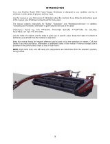
1 INTRODUCTION
This manual describes the operating and maintenance procedures for the MacDon Model R80 Pull-Type Rotary
Disc Mower Conditioner. Your new MacDon rotary disc mower conditioner is designed to cut, condition, and lay
in windrows a wide variety of grasses and hay crops.
CAREFULLY READ ALL THE MATERIAL PROVIDED BEFORE ATTEMPTING TO UNLOAD, ASSEMBLE, OR
USE THE MACHINE.
.
Use this manual as your first source of information about the machine. If you follow the instructions given in this
manual, your mower conditioner will work well for many years. A Parts Catalog is also supplied with your new
header. If you require more detailed service information, a Service Manual is available from your dealer.
Use the Table of Contents and the Index to guide you to specific areas. Study the Table of Contents to familiarize
yourself with how the material is organized.
Keep this manual handy for frequent reference and to pass on to new operators or owners. Call your dealer if you
need assistance, information, or additional copies of this manual. Store the Operator’s Manual and the Parts
Catalog in the plastic manual case inside the header right hand side drive compartment.
RECORD THE SERIAL NUMBERS OF THE HEADER AND ARTICULATING POWER TONGUE (APT) IN THE
SPACES BELOW.
HEADER SERIAL NUMBER:
____________________________________
Serial Number plate is located on the top surface at
the right hand end of the header.
APT SERIAL NUMBER:
___________________________________
Serial Number plate is located at the left front side of
the APT.

TABLE OF CONTENTS
Form # 169053 2 Model Year - 2009
Section/Title Page
1
INTRODUCTION............................................................................................................................................... 1
2 SAFETY ............................................................................................................................................................ 5
2.1 SAFETY ALERT SYMBOL ....................................................................................................................... 5
2.2 SIGNAL WORDS...................................................................................................................................... 5
2.3 SAFETY SIGNS........................................................................................................................................ 5
2.3.1 Safety Sign Installation ......................................................................................................................... 5
2.3.2 Safety Sign Locations ........................................................................................................................... 6
2.4 GENERAL SAFETY................................................................................................................................ 10
3 ACCRONYMS AND ABBREVIATIONS ......................................................................................................... 11
4 COMPONENT IDENTIFICATION ................................................................................................................... 12
5 SPECIFICATIONS .......................................................................................................................................... 15
6 OPERATION ................................................................................................................................................... 17
6.1 OWNER/OPERATOR RESPONSIBILITIES........................................................................................... 17
6.2 OPERATIONAL SAFETY ....................................................................................................................... 17
6.3 TRACTOR SETUP ................................................................................................................................. 19
6.3.1 Tractor Requirements ......................................................................................................................... 19
6.3.2 Drawbar Adjustment ........................................................................................................................... 19
6.3.3 Drawbar Hitch Set-Up ......................................................................................................................... 19
6.3.4 3 Point Hitch (Cat. II, III, or IIIN) Set-Up ............................................................................................. 20
6.4 MOWER CONDITIONER/ TRACTOR HOOK-UP.................................................................................. 22
6.4.1 Drawbar Hook-Up ............................................................................................................................... 22
6.4.2 3 Point Hitch (Cat. II, III, or IIIN) Hook-Up .......................................................................................... 23
6.4.3 Hydraulic Connections ........................................................................................................................ 25
6.5 MOWER CONDITIONER/ TRACTOR UNHOOK................................................................................... 26
6.5.1 Drawbar Unhook ................................................................................................................................. 26
6.5.2 3-Point Hitch Unhook .......................................................................................................................... 27
6.6 BREAK-IN PERIOD ................................................................................................................................ 29
6.7 PRE-SEASON CHECK........................................................................................................................... 29
6.8 DAILY START-UP CHECK..................................................................................................................... 29
6.9 SHUTDOWN PROCEDURE................................................................................................................... 30
6.10 ENGAGING THE PTO............................................................................................................................ 30
6.11 STEERING.............................................................................................................................................. 31
6.11.1 Right Side Operation........................................................................................................................... 31
6.11.2 Left Side Operation ............................................................................................................................. 31
6.11.3 Avoiding Obstacles ............................................................................................................................. 32
6.11.4 Square Corners................................................................................................................................... 32
6.11.5 180 Degree Turn................................................................................................................................. 33
6.12 TRANSPORTING MOWER CONDITIONER.......................................................................................... 34
6.12.1 Transporting With A Tractor................................................................................................................ 34
6.12.2 Transporting With a Truck................................................................................................................... 34
6.12.3 Preparing Windrower for Transport..................................................................................................... 36
6.12.4 Flatbed ................................................................................................................................................ 37
6.13 HEADER OPERATION........................................................................................................................... 41
6.13.1 Cutting Height ..................................................................................................................................... 41
6.13.2 Header Angle ...................................................................................................................................... 42
6.13.3 Header Flotation ................................................................................................................................. 43
6.13.4 Roll Gap and Timing ........................................................................................................................... 44
6.13.5 Roll Tension ........................................................................................................................................ 46
6.13.6 Forming Shields .................................................................................................................................. 47
6.13.7 Ground Speed..................................................................................................................................... 49
6.14 UNPLUGGING THE MOWER CONDITIONER...................................................................................... 50
6.15 HAYING TIPS ......................................................................................................................................... 50
6.15.1 Curing.................................................................................................................................................. 50
6.15.2 Topsoil Moisture.................................................................................................................................. 50
6.15.3 Weather and Topography ................................................................................................................... 50
6.15.4 Windrow Characteristics ..................................................................................................................... 51

TABLE OF CONTENTS
Form # 169053 3 Model Year - 2009
6.15.5 Driving On Windrow ............................................................................................................................ 51
6.15.6 Raking And Tedding ........................................................................................................................... 51
6.15.7 Chemical Drying Agents ..................................................................................................................... 51
6.16 STORAGE .............................................................................................................................................. 51
7 MAINTENANCE/SERVICE ............................................................................................................................. 52
7.1 PREPARATION FOR SERVICING ........................................................................................................ 52
7.2 RECOMMENDED SAFETY PROCEDURES ......................................................................................... 52
7.3 MAINTENANCE SPECIFICATIONS ......................................................................................................53
7.3.1 Recommended Torques ..................................................................................................................... 53
7.3.2 Recommended Lubricants.................................................................................................................. 55
7.3.3 Conversion Chart................................................................................................................................ 56
7.4 LIFT CYLINDER LOCK-0UT VALVES ...................................................................................................57
7.5 DRIVE SHIELDS .................................................................................................................................... 57
7.6 CUTTERBAR DOORS............................................................................................................................ 58
7.7 LUBRICATING THE WINDROWER.......................................................................................................59
7.7.1 Procedure............................................................................................................................................ 59
7.7.2 Lubrication Points ............................................................................................................................... 59
I. 13 FT Header................................................................................................................................. 60
II. 16 FT Header................................................................................................................................. 62
III. Carrier Frame................................................................................................................................. 64
IV. Driveline ......................................................................................................................................... 65
7.8 CUTTERBAR.......................................................................................................................................... 66
7.8.1 Skid Plates and Rock Guards............................................................................................................. 66
7.8.2 Cutter Bar Lubrication......................................................................................................................... 68
7.8.3 Disc Maintenance ............................................................................................................................... 69
7.8.4 Cutter Blades ...................................................................................................................................... 72
7.8.5 Accelerators ........................................................................................................................................ 75
7.8.6 Hourglass Deflectors........................................................................................................................... 76
7.8.7 Tall Crop Feed Plates ......................................................................................................................... 79
7.9 HEADER DRIVE..................................................................................................................................... 81
7.9.1 Pump Gearbox.................................................................................................................................... 81
7.9.2 Bevel Gearbox .................................................................................................................................... 81
7.9.3 Conditioner Gearbox – 13 Ft............................................................................................................... 87
7.9.4 Conditioner Gearbox – 16 Ft............................................................................................................... 91
7.9.5 Conditioner Drive Belt......................................................................................................................... 95
7.9.6 Conditioner Drive Belt Idler................................................................................................................. 97
7.9.7 Lifting Roll Drive Belt........................................................................................................................... 98
7.9.8 Lifting Roll Belt Idler ............................................................................................................................ 99
7.9.9 Lifting Roll Idler Bearing...................................................................................................................... 99
7.9.10 Hourglass Deflector Drive Belts – 16 Ft............................................................................................ 100
7.10 HYDRAULIC DRIVE SYSTEM ............................................................................................................. 102
7.10.1 Reservoir........................................................................................................................................... 102
7.10.2 Hydraulic Oil Filter............................................................................................................................. 103
7.10.3 Pressure Relief Valve ....................................................................................................................... 103
7.10.4 Pump................................................................................................................................................. 104
7.10.5 Hydraulic Motor................................................................................................................................. 106
7.10.6 Hoses and Lines ............................................................................................................................... 106
7.11 ELECTRICAL........................................................................................................................................ 107
7.11.1 Light Bulb Replacement.................................................................................................................... 107
7.11.2 Fixture Replacement......................................................................................................................... 107
7.12 WHEELS AND TIRES .......................................................................................................................... 109
7.12.1 Wheel Bolts....................................................................................................................................... 109
7.12.2 Wheel - Removal/Installation ............................................................................................................ 109
7.12.3 Tire Inflation ...................................................................................................................................... 111
7.13 MAINTENANCE SCHEDULE............................................................................................................... 112
7.13.1 Break-In Inspection ........................................................................................................................... 112
7.13.2 Interval Maintenance......................................................................................................................... 113
8 TROUBLESHOOTING.................................................................................................................................. 115

TABLE OF CONTENTS
Form # 169053 4 Model Year - 2009
8.1
MOWER PERFORMANCE................................................................................................................... 115
8.2 MECHANICAL ...................................................................................................................................... 117
9 OPTIONS AND ATTACHMENTS................................................................................................................. 119
9.1 GAUGE ROLLER KIT........................................................................................................................... 119
9.2 SKID SHOE KIT.................................................................................................................................... 119
9.3 SKID PLATE LIFT KIT .......................................................................................................................... 119
9.4 TALL CROP DIVIDER KIT.................................................................................................................... 119
9.5 CUTTERBAR REPAIR TOOL KIT........................................................................................................ 119
9.6 HYDRAULIC CENTER LINK KIT.......................................................................................................... 119
10 UNLOADING AND ASSEMBLY................................................................................................................... 120
INDEX .................................................................................................................................................................... 121

SAFETY
Form # 169053 5 Model Year - 2009
2 SAFETY
2.1 SAFETY ALERT SYMBOL
This safety alert symbol indicates important
safety messages in this manual and on safety
signs on the machine.
This symbol means:
ATTENTION!
BECOME ALERT!
YOUR SAFETY IS INVOLVED!
Carefully read and follow the safety message
accompanying this symbol.
WHY IS SAFETY IMPORTANT TO YOU?
ACCIDENTS DISABLE AND KILL
ACCIDENTS COST
ACCIDENTS CAN BE AVOIDED
2.2 SIGNAL WORDS
Note the use of the signal words DANGER,
WARNING, and CAUTION with safety
messages. The appropriate signal word for each
message has been selected using the following
guidelines:
DANGER
Indicates an imminently hazardous situation
that, if not avoided, will result in death or
serious injury.
WARNING
Indicates a potentially hazardous situation
that, if not avoided, could result in death or
serious injury. It is also used to alert against
unsafe practices.
CAUTION
Indicates a potentially hazardous situation
that, if not avoided, may result in minor or
moderate injury. It is also used as a reminder
of good safety practices.
2.3 SAFETY SIGNS
• Keep safety signs clean and legible at all
times.
• Replace safety signs that are missing or
become illegible.
• If original parts on which a safety sign was
installed are replaced, be sure the repair
part also bears the current safety sign.
• Safety signs are available from your Dealer
Parts Department.
2.3.1 Safety Sign Installation
a. Be sure the installation area is clean and dry.
b. Decide on the exact location before you remove
the decal backing paper.
c. Remove the smaller portion of the split backing
paper.
d. Place the sign in position and slowly peel back
the remaining paper, smoothing the sign as it is
applied.
e. Small air pockets can be smoothed out or
pricked with a pin.

SAFETY
Form # 169053 6 Model Year - 2009
2.3.2 Safety Sign Locations
(BOTH SIDES) #32738
#134070
#170281
#148829
(BOTH SIDES) #115100
#109843

SAFETY
Form # 169053 7 Model Year - 2009
Safety Sign Locations
(cont’d)
#44944
BOTH SIDES #142677
#109843
#115148

SAFETY
Form # 169053 8 Model Year - 2009
Safety Sign Locations (cont’d)
#142909
#36651

SAFETY
Form # 169053 9 Model Year - 2009
Safety Sign Locations
(cont’d)
#142752
#142912
#44944

SAFETY
Form # 169053 10 Model Year - 2009
2.4 GENERAL SAFETY
CAUTION
The following are general farm safety
precautions that should be part of your
operating procedure for all types of machinery.
• Protect yourself.
• When assembling, operating and servicing
machinery, wear all the protective clothing
and personal safety devices that COULD be
necessary for the job at hand. Don't take
chances.
• You may need:
o a hard hat.
o protective shoes with slip resistant
soles.
o protective glasses or goggles.
o heavy gloves.
o wet weather gear.
o respirator or filter mask.
o hearing protection. Be aware that
prolonged exposure to loud noise
can cause impairment or loss of
hearing. Wearing a suitable hearing
protective device such as ear muffs
(A) or ear plugs (B) protects against
objectionable or loud noises.
• Provide a first-aid kit for use in case of
emergencies.
• Keep a fire extinguisher on the machine. Be
sure the extinguisher is properly maintained
and be familiar with its proper use.
• Keep young children away from machinery at
all times.
• Be aware that accidents often happen when
the operator is tired or in a hurry to get
finished. Take the time to consider the safest
way. Never ignore warning signs of fatigue.
• Wear close-fitting clothing
and cover long hair. Never
wear dangling items such as
scarves or bracelets.
• Keep hands, feet, clothing
and hair away from moving
parts. Never attempt to clear
obstructions or objects from
a machine while the engine
is running.
• Keep all shields in place. Never alter or
remove safety equipment. Make sure
driveline guards can rotate independently of
the shaft and can telescope freely.
• Stop engine and remove key from ignition
before leaving operator's seat for any
reason. A child or even a pet could engage
an idling machine.
• Keep machinery clean. Do not allow oil or
grease to accumulate on service platforms,
ladders or controls. Clean machines before
storage.
• When storing machinery, cover sharp or
extending components to prevent injury from
accidental contact.
A
B

GENERAL
Form # 169053 11 Model Year - 2009
3 ACCRONYMS AND
ABBREVIATIONS
TERM DEFINITION
API
American Petroleum Institute
APT
Articulating Power Tongue
ASTM
American Society Of Testing And
Materials
C
Celsius
F
Fahrenheit
ft/min feet per minute
ft/s feet per second
gpm U.S. gallons per minute
hp horsepower
in.
3
cubic inches
kPa
kilopascals
lbf
pounds force
lbf·ft or ft·lbf
pound feet or foot pounds
lbf·in or in·lbf
pound inches or inch pounds
mPa
megapascals
mph
miles per hour
N
newtons
N·m
newton meters
oz.
ounces
psi
pounds per square inch
PTO
Power Take-Off
rpm
Revolutions Per Minute
SAE
Society Of Automotive Engineers

GENERAL
Form # 169053 12 Model Year - 2009
4 COMPONENT
IDENTIFICATION
13 FT MODEL
ARTICULATING
POWER TONGUE (APT)
FRONT CURTAIN HEADER
STEERING
CYLINDER
DRIVE MOTOR CENTER LINK CARRIER FRAME
DOOR
TAIL-LIGHT
BAFFLE CONTROL
FLOAT SPRING
HAZARD LIGHT
FLUFFER SIDE DEFLECTOR
LIFT CYLINDER
LOCK VALVE
DRIVE SHIELD CUTTERBAR
MANUAL CASE

GENERAL
Form # 169053 13 Model Year - 2009
16 FT MODEL
FLUFFER SIDE DEFLECTOR
LIFT CYLINDER
LOCK VALVE
DRIVE SHIELD CUTTERBAR GAUGE ROLLER
DOOR
TAIL-LIGHT
BAFFLE CONTROL
HAZARD LIGHT FLOAT SPRING
ARTICULATING
POWER TONGUE
STEERING
CYLINDER
DRIVE MOTOR
FRONT CURTAIN HEADER
CENTER LINK CARRIER FRAME
MANUAL CASE
HAZARD LIGHT

GENERAL
Form # 169053 14 Model Year - 2009
STEERING CYLINDER LOCKOUT VALVE
CONTROL HOSES
PUMP AND GEARBOX
DRIVELINE
SAFETY CHAIN
JACK
DRAWBAR HITCH
13 & 16 FT MODELS
ARTICULATING POWER TONGUE (APT)
3-POINT HITCH YOKE TOWING ADAPTER

SPECIFICATIONS
Form # 169053 15 Model Year - 2009
5 SPECIFICATIONS
(continued next page)
HEADER MODEL
R80 – 13 FT R80 – 16 FT
FRAME & STRUCTURE
Width
13 ft-0 in. (3952 mm) 16 ft-3 in. (4957 mm)
Weight (estimated) 6200 lb (2818 kg) 7130 lb (3240 kg)
Carrier
Pull-Type
Lighting
Two Amber Transport and Two Red Tail-Lights
Wheels/Tires
16 in. / 10.00x16 – 4 Rib 16 in. / 14Lx16.1 8 Ply
Tread Width
143 in. (3265 mm) 150 in. (3800 mm)
Manual Storage
Plastic Case In Header RH Drive Compartment
CUTTERBAR
Qty Of Cutting Discs
8 10
Knives Per Disc
Two 18 Deg. Bevel Down Reversible (11 Deg. Optional)
Disc Speed 2530 rpm
Knife Tip Speed Range
184 mph (82.9 m/s)
Effective Cutting Width
12 ft-9.37 in. (3895 mm) 16 ft-0.87 in. (4899 mm)
Cutting Height
1 to 3 in. (25-75 mm) Without Lift Kit 1 to 3 in. (25-75 mm) Without Lift Kit
Oil Capacity (Maximum)
7 Pints (3.25 Litres) 9 Pints (4.25 litres)
Cutting Angle Range
0-8 Deg Below Horizontal
Geartrain Protection
Shearable Disc Spindles
Deflectors 2 Hourglass Converging 6 Hourglass Converging
DRIVES
Tractor PTO 1.375 in. (35 mm) Dia. 21 Spline or 1.75 in. (44 mm) Dia. 20 Spline
Connections Quick Attachment Coupling
Hydraulic Pump Step-Up Gearbox to 4.9 cu in. (80 cc) Pump
Hydraulic Motor
3.7 cu in. (60 cc) To Gearbox
Power Developed (max) 143 hp (107 kW)
Normal Operating Pressure 2000 psi (13.71 MPa)
CONDITIONER
Drive Bevel Gearbox To Belt Driven Enclosed Timing Gearbox And Driveline.
Bevel Gearbox Lub.
Capacity
0.9 Pints (0.4 Litres)
Roll Type Intermeshing Steel Bars
Main 9.17 in. (233 mm)/6.62 in. (168 mm) OD Tube
Roll Diameter
Lifting 9.21 in. (234 mm)/6.62 in. (168 mm) OD Tube
Main 118 in. (3000 mm)
Roll Length
Lifting 118 in. (3000 mm)
Main 1035 rpm
Roll Speed
Lifting 690 rpm
Swath Width 36-102 in. (915-2540 mm)
Forming Shields
Header Mounted Adjustable Baffle, Fixed Side Deflectors, and Header Mounted Adjustable Forming
Shield System.

SPECIFICATIONS
Form # 169053 16 Model Year - 2009
NOTES: 1. Specifications and design are subject to change without notice or obligation to revise previously
sold units.
2. Tractor must be equipped with a cab.
HEADER MODEL
R80 – 13 FT R80 – 16 FT
GROUND SPEED
Recommended Cutting
8-11 mph (13-18 km/h)
Recommended Transport
20 mph (30 km/h)
TRACTOR REQUIREMENTS
PTO Power - Minimum
120 hp (90 kW) 150 hp (112 kW)
Pressure
2000 psi (13.71 MPa)
Hydraulics
Controls
Two Double-Acting / One Single-Acting

OPERATION
Form # 169053 17 Model Year - 2009
6 OPERATION
6.1 OWNER/OPERATOR
RESPONSIBILITIES
CAUTION
• It is your responsibility to read and
understand this manual completely
before operating the mower conditioner.
Contact your dealer if an instruction is
not clear to you.
• Follow all safety messages in the manual
and on safety signs on the machine.
• Remember that YOU are the key to
safety. Good safety practices protect you
and the people around you.
• Before allowing anyone to operate the
mower conditioner, for however short a
time or distance, make sure they have
been instructed in its safe and proper
use.
• Review the manual and all safety related
items with all operators annually.
• Be alert for other operators not using
recommended procedures or not
following safety precautions. Correct
these mistakes immediately, before an
accident occurs.
• Do not modify the machine. Unauthorized
modifications may impair the function
and/or safety and affect machine life.
• The safety information given in this
manual does not replace safety codes,
insurance needs, or laws governing your
area. Be sure your machine meets the
standards set by these regulations.
• Ensure that the tractor is properly
equipped to safely operate the mower
conditioner. This may include adding
ballast according to Tractor Operator’s
Manual requirements for attachments of
this size and mass.
6.2 OPERATIONAL SAFETY
Follow these safety precautions:
CAUTION
• Follow all safety and operational
instructions given in your tractor
Operator's Manual. If you do not have a
tractor manual, get one from your dealer
and read it thoroughly.
• Never attempt to start the tractor engine
or operate the mower conditioner except
from the tractor seat.
• Check the operation of all controls in a
safe clear area before starting work.
• Do not allow riders on tractor or mower
conditioner.
• Never start or move the machine until
you are sure all bystanders have cleared
the area.
• Avoid travelling over loose fill, rocks,
ditches or holes.
• Drive slowly through gates and
doorways.
• If cutting ditch banks, use extreme
caution. If the mower conditioner hits an
obstruction, the front of the tractor will
usually swerve towards the ditch.
• When working on inclines, travel uphill or
downhill when possible. Be sure to keep
tractor transmission in gear when
travelling downhill.
• Never attempt to get on or off a moving
tractor.
• Do not get off the tractor while the mower
conditioner is in operation.
• Stop tractor engine and remove key
before adjusting or removing plugged
material from the machine. A child or
even a pet could engage the drive.
• Check for excessive vibration and
unusual noises. If there is any indication
of trouble, shut down and inspect the
machine. Follow proper shutdown
procedure:
o engage tractor brake
o disengage PTO
o turn off engine and remove key
o wait for all movement to stop
o dismount and close lift cylinder
valves before inspecting raised
machine.
(continued next page)

OPERATION
Form # 169053 18 Model Year - 2009
• Operate only in daylight or good artificial
light.
• Keep everyone several hundred feet
away from your operation. Ensure
bystanders are never in line with the
front or rear of the machine. Stones or
other foreign objects can be ejected from
either end with force.
• Extreme care must be exercised to avoid
injury from thrown objects. Do not,
under any circumstances, operate the
mower-conditioner when other people
are in the vicinity. Stones and other
objects can be thrown great distances by
the rotating cutting blades.
• The cutterbar curtains are very important
to reduce the potential for thrown
objects. Always keep these curtains
down when operating the mower-
conditioner. Replace the curtains if they
should become worn or damaged.
/