Page is loading ...

Model 972
HARVEST HEADER
Model 742
HAY CONDITIONER
OPERATOR’S MANUAL
Form 46290 Issue 09/05
Sugg. Retail: $15.00

Inside Front Cover
(blank)

Form # 46290 Issue 09/05
1
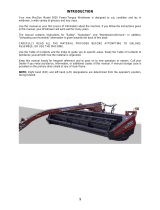
INTRODUCTION
Your new 972 Harvest Header is designed to serve a dual function in your grain, hay and specialty crop
harvesting operation:
1. Teamed with your self-propelled windrower power unit and optional hay conditioner, the header will cut
and lay crop into uniform fluffy windrows. Windrowing allows starting the harvest earlier, protects the crop
from wind damage, and gives you more flexibility in scheduling combine time. (The end-delivery capability
of the 21 to 36 foot models of 972 allows the option of using your combine as the power unit when
windrowing.)
2. When conditions are right for straight cutting, the 21 foot to 36 foot headers can quickly be attached to
your combine using a model 872 Adapter. When weather is not a critical factor, straight cutting eliminates
the windrowing operation.
NOTE: This manual contains information on the 972 Harvest Header and 742 Hay Conditioner. It must be
used in conjunction with your Windrower, Tractor and/or Combine Operator's Manual. As well, a separate
manual is provided for the adapter that is required to allow attachment of the header to the various makes and
models of combines and tractors.
CAREFULLY READ ALL MANUALS TO BECOME FAMILIAR WITH RECOMMENDED PROCEDURES
BEFORE ATTEMPTING TO UNLOAD, ASSEMBLE OR USE THE MACHINE.
Use this manual as your first source of information about the header. If you follow the instructions given in this
manual your Harvest Header will work well for many years.
This manual contains information on "Safety", "Operation" and "Maintenance/Service". In addition, "Unloading
and Assembly" instruction is given towards the back of this book.
Use the Table of Contents and the Index to guide you to specific areas. Study the Table of Contents to
familiarise yourself with how the material is organised.
Keep this manual handy for frequent reference and to pass on to new operators or owners. Call your dealer if
you need assistance, information or additional copies of the manual.
NOTE: Right hand (R/H) and Left-hand (L/H) designations are determined from the operator’s position, facing
forward.
NOTE: On 21’ to 36’ “combine-configured” headers, a storage case for this manual is located under the left
endsheet.

Form # 46290 Issue 09/05
2
TABLE OF CONTENTS
INTRODUCTION.........................................................................................................................................1
SERIAL NUMBER LOCATION ...................................................................................................................5
SAFETY
Safety Alert Symbol................................................................................................................................6
Signal Words..........................................................................................................................................6
Safety Signs...........................................................................................................................................7
General Farm Safety...........................................................................................................................8,9
SPECIFICATIONS
972 Harvest Header.............................................................................................................................10
742 Hay Conditioner ...........................................................................................................................10
Upper Cross Auger .............................................................................................................................10
Hardware Torque Specifications..........................................................................................................11
Hydraulic Fittings Torque Specifications..............................................................................................12
HEADER OPERATION
Your Responsibilities as an Owner/Operator.......................................................................................13
Attaching the Hay Conditioner ....................................................................................................... 14-16
Detaching the Hay Conditioner ............................................................................................................17
Break-In Period ....................................................................................................................................18
Pre-Starting Checks: Annual................................................................................................................19
Pre-Starting Checks: Daily...................................................................................................................19
Operate Correctly.................................................................................................................................20
Header Controls...................................................................................................................................21
Header Lift Cylinder Stops ...................................................................................................................21
Reel Props ...........................................................................................................................................21
Operating Variables ...........................................................................................................................22
Cutting Height: Grain Crops – Gauge Wheels ..................................................................................22
Cutting Height: Hay & Specialty Crops – Skid Shoes/Gauge Rollers ...............................................23
Divider Rod Length............................................................................................................................24
Ground Speed...................................................................................................................................25
Header Flotation................................................................................................................................26
Header Angle ....................................................................................................................................27
Draper Speed....................................................................................................................................27
Delivery Opening Width............................................................................................................... 27-31
End Delivery: Manual Shift Headers .................................................................................................31
End delivery: Hydraulic Shift Headers...............................................................................................32
Reel Speed........................................................................................................................................33
Reel Height........................................................................................................................................33
Reel Fore-Aft Position .......................................................................................................................34
Reel Pick-Up Finger Pitch .................................................................................................................35
Upper Cross Auger (Optional)...........................................................................................................36
Forming Rods....................................................................................................................................36
Effects of Operating Variables on Windrow Formation ................................................................37,38
Windrow Characteristics...............................................................................................................39,40
Hay Conditioner Roll Intermesh ........................................................................................................41
Hay Conditioner Roll Tension Springs ..............................................................................................41
Hay Conditioner Ground Clearance ..................................................................................................42
Hay Conditioner Float........................................................................................................................43
Hay Conditioner Forming Shields.................................................................................................44,45
Haying Tips ..................................................................................................................................45,46
Shut-Down Procedure..........................................................................................................................46
Unplugging the Header and Conditioner..............................................................................................47
Transporting the Header on Windrower or Combine ...........................................................................48
Storage Procedure...............................................................................................................................49

Form # 46290 Issue 09/05
3
TABLE OF CONTENTS
MAINTENANCE/SERVICE
Service Procedures..............................................................................................................................50
Recommended Lubricants ...................................................................................................................51
Sealed Bearing Installation ..................................................................................................................51
Greasing the Header...................................................................................................................... 52-55
Greasing the Hay Conditioner..............................................................................................................55
Hydraulic System
Hydraulic System Safety ...................................................................................................................56
Hoses and Lines................................................................................................................................56
Hydraulic Schematic – Reel Lift ........................................................................................................56
Hydraulic Schematic – Reel & Draper Drive on Windrower ..............................................................57
Hydraulic Schematic – Reel & Conveyor Drives (Manual Shift Header) on Combine.......................58
Electrical .............................................................................................................................................59
Sickle and Sickle Drive
Sickle Lubrication ..............................................................................................................................59
Sickle Sections..................................................................................................................................60
Sickle Removal..................................................................................................................................60
Sickle Head Needle Bearing Installation ...........................................................................................61
Sickle Installation...............................................................................................................................61
Spare Sickle Storage.........................................................................................................................62
Sickle Guards....................................................................................................................................62
Sickle Hold-Downs ............................................................................................................................63
Stub Guards and Top Guides............................................................................................................63
Wobble Box.......................................................................................................................................64
Single Sickle Drive Conversion .........................................................................................................65
Single Sickle Drive Belt Tension .......................................................................................................65
Double Sickle Speed.........................................................................................................................66
Double Sickle Drive Belt Tension......................................................................................................66
Double Sickle Drive Belt Tracking.....................................................................................................67
Double Sickle Timing.........................................................................................................................67
Drapers
Draper Tension Adjustment...............................................................................................................68
Replacing Drapers.............................................................................................................................68
Draper Drive Motor Locations ...........................................................................................................69
Idler Roller Positioning ......................................................................................................................69
Draper Tracking Adjustment..............................................................................................................70
Idler Roller Maintenance ...................................................................................................................70
Drive Roller Maintenance..................................................................................................................71
Deck Height.......................................................................................................................................71
Reel and Reel Drive
Reel Clearance to Cutterbar..............................................................................................................72
Reel "Frown" Adjustment ..................................................................................................................72
Reel Plastic Finger Installation & Removal .......................................................................................73
Centering the Reel ............................................................................................................................74
Reel Drive Chain ...............................................................................................................................74
Removal of Reel Drive Shaft.............................................................................................................74
Gauge Wheels.....................................................................................................................................75
Hay Conditioner
Hay Conditioner Drive Chain.............................................................................................................76
Hay Conditioner Roll Timing..............................................................................................................76
Maintenance Schedule.........................................................................................................................77
Maintenance Record............................................................................................................................78
TROUBLE SHOOTING
Crop Loss at Cutterbar....................................................................................................................79,80
Cutting Action & Sickle Components ............................................................................................. 80-82
Reel Delivery...................................................................................................................................82,83
Header .................................................................................................................................................83
Drapers & Decks..................................................................................................................................84
Windrow Formation - Grain.............................................................................................................84,85
Hay Conditioner ...................................................................................................................................86
Windrow Formation - Hay ....................................................................................................................86
Cutting Edible Beans...................................................................................................................... 87-90

Form # 46290 Issue 09/05
4
TABLE OF CONTENTS
OPTIONS AND ATTACHMENTS
Hydraulic Deck Shift Package..............................................................................................................91
Narrow Opening Kit..............................................................................................................................91
Hydraulic Fore-Aft Reel Positioner.......................................................................................................91
Hay Conditioner ...................................................................................................................................91
Forming Rods (Center Opening)..........................................................................................................92
End Delivery Forming Rods .................................................................................................................92
Tall Crop Divider ..................................................................................................................................92
Floating Divider ....................................................................................................................................92
Special Narrow Deflectors....................................................................................................................92
Plastic Wear Strips & Shoes ................................................................................................................93
Cutterbar Poly Wear Strips ..................................................................................................................93
Upper Cross Auger ..............................................................................................................................93
Stub Guard Conversion Kit ..................................................................................................................93
Gauge Wheels .....................................................................................................................................94
Gauge Rollers ......................................................................................................................................94
Adjustable Skid Shoes – Outboard ......................................................................................................94
Adjustable Skid Shoes With Poly Cover – Outboard ...........................................................................94
Adjustable Skid Shoes – Inboard.........................................................................................................95
Gauge Wheels/Slow Speed Transport – 30’ & 36’...............................................................................95
Transport Kit – 21’ & 25’.......................................................................................................................95
Combine Header / Windrower Header Conversion Kits.......................................................................96
36’ Header: R/H Deck Split Kit.............................................................................................................96
Raised Sickle Conversion Kits .............................................................................................................96
Reel Drive Sprockets ...........................................................................................................................97
Conditioned Windrow Side Delivery System........................................................................................97
UNLOADING AND ASSEMBLY
Unloading........................................................................................................................................98,99
Pull Header Over to Field Position.....................................................................................................100
Set Header Support Stand.................................................................................................................100
Reel Support Arms......................................................................................................................101,102
Reel Assembly ...................................................................................................................................103
End Delivery.......................................................................................................................................103
Draper Installation.......................................................................................................................104,105
Header Assembly...............................................................................................................................105
Prepare Header for Windrower or Combine – 21’ to 36’....................................................................106
Moving Draper Motors Outboard or Inboard .............................................................................. 106-108
Bleeding Hydraulics ...........................................................................................................................109
Prepare Header for Hay Conditioner..................................................................................................110
Prepare Tractor for Hay Conditioner..................................................................................................111
Assemble Hay Conditioner Forming Shields & Deflector Fins................................................... 112-113
Installing Hay Conditioner Drive Belts................................................................................................113
Hay Conditioner Assembly Illustration ...............................................................................................114
Attaching Hay Conditioner ....................................................................................................... 115 - 118
Adjustments and Checks ...................................................................................................................119
INDEX ..............................................................................................................................................120,121

Form # 46290 Issue 09/05
5
SERIAL NUMBER LOCATION
Record the serial number in the space provided.
972 Harvest Header:
Plate is located on gusset at left hand end
sheet, near main tube.
742 Hay Conditioner:
Plate is located at rear left side of top sheet.
NOTE: When ordering parts and service, be sure to give your dealer the complete and proper serial number.
HEADER SERIAL PLATE
HAY CONDITIONER SERIAL PLATE

Form # 46290 Issue 09/05
6
SAFETY
SAFETY ALERT SYMBOL
This safety alert symbol indicates important safety messages in this manual and
on safety signs on the header.
This symbol means:
ATTENTION !
BECOME ALERT !
YOUR SAFETY IS INVOLVED !
Carefully read and follow the safety message accompanying this symbol.
Why is SAFETY important to you?
· ACCIDENTS DISABLE AND KILL
3 BIG REASONS · ACCIDENTS COST
· ACCIDENTS CAN BE AVOIDED
SIGNAL WORDS
Note the use of the signal words DANGER, WARNING, and CAUTION with safety messages. The appropriate
signal word for each message has been selected using the following guidelines:
DANGER – Indicates an imminently hazardous situation that, if not avoided, will result in death or
serious injury.
WARNING – Indicates a potentially hazardous situation that, if not avoided, could result in death
or serious injury. It is also used to alert against unsafe practices.
CAUTION – Indicates a potentially hazardous situation that, if not avoided, may result in minor or
moderate injury. It is also used as a reminder of good safety practices.
SAFETY SIGNS
• The safety signs reproduced on the next page appear on the header at the locations listed.
• Keep safety signs clear and legible at all times.
• Replace safety signs that are missing or become illegible.
• If original parts on which a safety sign was installed are replaced, be sure the repair part also bears the
current safety sign.
• Safety signs are available from your Dealer Parts Department.
To install safety signs:
1. Be sure the installation area is clean and dry.
2. Decide on the exact position before you remove the backing paper.
3. Remove the smaller portion of the split backing paper.
4. Place the sign in position and slowly peel back the remaining paper, smoothing the sign as it is applied.
5. Small air pockets can be smoothed out or pricked with a pin

Form # 46290 Issue 09/05
7
R/H WHEEL
(TRANSPORT OPTION)
Order # 129260.
SAFETY
SAFETY SIGNS
DRIVELINE
Order # 30316.
BACK TUBE
Order # 44611.
HITCH
(TRANSPORT OPTION)
Order # 129261.
UPPER CROSS AUGER OPTION
Order # 158621.
BACK TUBE
Order # 42122.
BACK TUBE
Order # 32009.

Form # 46290 Issue 09/05
8
SAFETY
GENERAL SAFETY
The following are general farm safety
precautions that should be part of
your operating procedure for all
types of machinery.
1. Protect yourself.
When assembling, operating and servicing
machinery wear all the protective clothing
and personal safety devices that COULD be
necessary for the job at hand. Don't take
chances.
You may need:
• a hard hat.
• protective shoes with slip resistant soles.
• protective glasses or goggles.
• heavy gloves.
• wet weather gear.
• respirator or filter mask.
• hearing protection. Be aware that prolonged
exposure to loud noise can cause
impairment or loss of hearing. Wearing a
suitable hearing protective device such as
earmuffs (A) or earplugs (B) protects
against objectionable or loud noises.
2. Provide a first-aid kit for use in case of
emergencies.
3. Keep a fire extinguisher on the machine. Be
sure the extinguisher is properly maintained
and be familiar with its proper use.
4. Keep young children away from machinery
at all times.
5. Be aware that accidents often happen
when the operator is tired or in a hurry to
get finished. Take the time to consider the
safest way. Never ignore warning signs of
fatigue.
PROTECT YOURSELF
PROTECT AGAINST NOISE
BE PREPARED FOR EMERGENCIES

Form # 46290 Issue 09/05
9
SAFETY
GENERAL SAFETY
(continued)
6. Wear close-fitting clothing and cover long
hair. Never wear dangling items such as
scarves or bracelets.
7. Keep hands, feet, clothing and hair away
from moving parts. Never attempt to clear
obstructions or objects from a machine
while the engine is running.
8. Keep all shields in place. Never alter or
remove safety equipment. Make sure
driveline guards can rotate independently of
the shaft and can telescope freely.
9. Use only service and repair parts made or
approved by the equipment manufacturer.
Substituted parts may not meet strength,
design, or safety requirements.
10. Do not modify the machine. Unauthorised
modifications may impair the function
and/or safety and affect machine life.
11. Stop engine and remove key from ignition
before leaving operator's seat for any
reason. A child or even a pet could engage
an idling machine.
12. Keep the area used for servicing machinery
clean and dry. Wet or oily floors are
slippery. Wet spots can be dangerous when
working with electrical equipment. Be sure
all electrical outlets and tools are properly
grounded.
13. Use adequate light for the job at hand.
14. Keep machinery clean. Straw and chaff on a
hot engine are a fire hazard. Do not allow oil
or grease to accumulate on service
platforms, ladders or controls. Clean
machines before storage.
15. Never use gasoline, naphtha or any volatile
material for cleaning purposes. These
materials may be toxic and/or flammable.
16. When storing machinery, cover sharp or
extending components to prevent injury
from accidental contact.
NEVER WEAR LOOSE
O
R DAN
G
LIN
G
C
L
O
THE
S
KEEP AWAY FROM MOVING PARTS
KEEP SERVICE AREA CLEAN AND DRY

Form # 46290 Issue 09/05
10
SPECIFICATIONS
972 Harvest Header
HEADER WIDTH 12’ = 165.1” (4194 mm)
Others = nominal cut width plus: 10.5” (267 mm) Single Sickle
15.1” (384 mm) Double Sickle
SINGLE SICKLE DRIVE "C" belt to enclosed oil bath wobble box
DOUBLE SICKLE DRIVE Timing belts to enclosed oil bath wobble boxes
SICKLE SPEED Single Sickle
Double Sickle
12, 15 & 18 ft. on windrower 1450 strokes per minute or 1875 spm*
21 & 25 ft. on windrower 1300 spm 1310 spm or 1695 spm*
30 & 36 ft. on windrower 1300 spm 1310 spm* or 1695 spm
21, 25, 30 & 36 ft. on combine 1175 to 1270 spm** 1138 to 1320 spm**
* - factory assembled at this speed
** - varies depending on combine
SICKLE TYPE Over-serrated, bolted sections
GUARD TYPE Stub or double heat-treated pointed
GUARD ANGLE: Combine 21’ & 25’ – 17° to 21° / 30’ & 36’ – 7° to 11° (cutterbar on ground)
Windrower 9.4° to 19.4° (varies with center link length & lift cylinder extension)
CUTTERBAR RANGE: Windrower
Shortest Center Link: 1" (25 mm) below ground to 41.7" (1060 mm) above
Longest Center Link: 5.5” (140 mm) below ground to 37.7" (960 mm) above
DRAPER TYPE Self-tracking rubber coated polyester with rubber slats
DRAPER WIDTH 41.5" (1055 mm)
DRAPER DRIVE Hydraulic
DRAPER SPEED 170 to 500 ft. per minute (50 to 155 m/min)
DELIVERY OPENING HEIGHT 32.3" to 36.2" (820 to 920 mm) at 8" (200 mm) cutting height
DELIVERY OPENING WIDTH Distance between draper rollers:
12, 15 & 18 ft. 56.5" or 64.5" (1435 mm or 1640 mm)
with draper extension kit 37.5" or 45.5" (955 mm or 1155 mm)
21, 25, 30 & 36 ft.: narrow deflectors 35.2" to 45.4" (895 mm to 1153 mm)
by shortening drapers: 54.1" to 64.5" (1375 mm to 1640 mm)
21, 25, 30 & 36 ft.: wide deflectors 30.5" to 45.4" (775 mm to 1153 mm)
by shortening drapers: 49.4" to 64.5" (1256 mm to 1640 mm)
REEL TYPE 6 Bat MacDon 2100 cam action pick-up reel (Bat reel option for 30 & 36’)
REEL FINGERS Plastic, 31.5" (800 mm) finger tip radius (Steel finger optional)
REEL DRIVE Hydraulic
REEL SPEED 20 to 60 RPM
REEL LIFT Hydraulic
WEIGHTS: Weights shown are base header plus plastic finger reel. (See below for weights for common options.)
S/S = Single sickle, D/S = Double Sickle, H/S = Hydraulically Shifted Decks, M/S = Manually Shifted Decks,
(C) = Combine Configuration, (W) = Windrower Configuration
12’ 2355 lbs. (1068 kg)
15’ 2595 lbs. (1177 kg)
18’ 2885 lbs. (1309 kg)
21’ S/S H/S 3050 lbs. (1383 kg)
21’ S/S M/S 2900 lbs. (1315 kg)
21’ D/S H/S 3240 lbs. (1470 kg)
25’ S/S H/S 3435 lbs. (1558 kg)
25’ S/S M/S (C) 3285 lbs. (1490 kg)
25’ S/S M/S (W) 3355 lbs. (1522 kg)
25’ D/S H/S 3640 lbs. (1651 kg)
30’ S/S H/S 4090 lbs. (1855 kg)
30’ S/S M/S (C) 3940 lbs. (1787 kg)
30’ S/S M/S (W) 4010 lbs. (1819 kg)
30’ D/S H/S 4330 lbs. (1964 kg)
30’ D/S M/S 4260 lbs. (1932 kg)
36’ S/S M/S (C) 4435 lbs. (2012 kg)
36’ S/S M/S (W) 4505 lbs. (2043 kg)
36’ D/S M/S (C) 4750 lbs. (2155 kg)
36’ D/S M/S (W) 4830 lbs. (2191 kg)
Outer Adjustable Skid Shoes – add 40 lbs. (18 kg)
Inner Adjustable Skid Shoes – add 38 lbs. (17 kg)
Gauge Rollers – add 115 lbs. (52 kg)
Gauge Wheels – add 200 lbs. (91 kg)
Hydraulic Reel Fore Aft, 2-arm – add 60 lbs. (27 kg)
Hydraulic Reel Fore Aft, 3 arm – add 86 lbs. (39 kg)
742 Hay Conditioner
TYPE Crimper - Intermeshing steel rolls,
Header mounted
ROLL WIDTH 65" (1650 mm)
ROLL DIAMETER 8" (200 mm)
SPEED 910 rpm
WEIGHT 805 lbs. (365 kg)
Upper Cross Auger
DRIVE Hydraulic
SPEED 140 to 390 rpm (varies with reel)
TYPE 9" (229 mm) diameter, center feed
WEIGHT 136 lbs. (62 kg)

Form # 46290 Issue 09/05
11
TORQUE SPECIFICATIONS
CHECKING BOLT TORQUE
The tables shown below give correct torque values for various bolts and capscrews. Tighten all bolts to the
torques specified in chart unless otherwise noted throughout this manual. Check tightness of bolts periodically,
using bolt torque chart as a guide. Replace hardware with the same strength bolt.
ENGLISH TORQUE SPECIFICATION
NC Bolt Torque*
SAE 5 SAE 8
Bolt
Dia.
"A"
N·m [lb-ft] N·m [lb-ft]
1/4" 12 [9] 15 [11]
5/16" 24 [18] 34 [25]
3/8" 43 [32] 56 [41]
7/16" 68 [50] 95 [70]
1/2" 102 [75] 142 [105]
9/16" 149 [110] 202 [149]
5/8" 203 [150] 271 [200]
3/4"
359 [265]
495 [365]
7/8" 569 [420] 813 [600]
1" 867 [640] 1205 [890]
METRIC TORQUE SPECIFICATIONS
Bolt Torque*
8.8
10.9
Bolt
Dia.
"A"
N·m
[
lb-ft
]
N·m
[
lb-ft
]
M3
0.5
[
.4
]
1.8
[
1.3
]
M4
3
[
2.2
]
4.5
[
3.3
]
M5
6
[
4
]
9
[
7
]
M6
10
[
7
]
15
[
11
]
M8
25
[
18
]
35
[
26
]
M10
50
[
37
]
70
[
52
]
M12
90
[
66
]
125
[
92
]
M14
140
[
103
]
200
[
148
]
M16
225
[
166
]
310
[
229
]
M20
435
[
321
]
610
[
450
]
M24
750
[
553
]
1050
[
774
]
M30
1495
[
1103
]
2100
[
1550
]
M36
2600
[1917]
3675
[2710]
Torque figures indicated above are valid for non-greased or non-oiled threads and heads unless otherwise
specified. Do not grease or oil bolts or capscrews unless specified in this manual. When using locking
elements, increase torque values by 5%.
* Torque value for bolts and capscrews are identified by their head markings.

Form # 46290 Issue 09/05
12
TORQUE SPECIFICATIONS
TIGHTENING O-RING FITTINGS*
1. Inspect O-ring and seat for dirt or obvious
defects.
2. On angle fittings, back the lock nut off until
washer bottoms out at top of groove.
3. Hand tighten fitting until back-up washer or
washer face (if straight fitting) bottoms on face
and O-ring is seated.
4. Position angle fittings by unscrewing no more
than one turn.
5. Tighten straight fittings to torque shown.
6. Tighten angle fittings to torque shown while
holding body of fitting with a wrench.
* The torque values shown are based on
lubricated connections as in reassembly.
Torque Value*
Recommended
Turns to Tighten
(after finger
tightening)
Thread
Size
(in.)
Nut Size
Across
Flats
(in.)
N·m
[lb-ft]
Flats Turns
3/8 1/2 8
[6]
2 1/3
7/16 9/16 12
[9]
2 1/3
1/2 5/8 16
[12]
2 1/3
9/16 11/16 24
[18]
2 1/3
3/4 7/8 46
[34]
2 1/3
7/8 1 62
[46]
1-1/2 1/4
1-1/16 1-1/4 102
[75]
1 1/6
1-3/16 1-3/8 122
[90]
1 1/6
1-5/16 1-1/2 142
[105]
3/4 1/8
1-5/8 1-7/8 190
[140]
3/4 1/8
1-7/8 2-1/8 217
[160]
1/2 1/12
TIGHTENING FLARE TYPE TUBE FITTINGS*
1. Check flare and flare seat for defects that
might cause leakage.
2. Align tube with fitting before tightening.
3. Lubricate connection and hand tighten swivel
nut until snug.
4. To prevent twisting the tube(s), use two
wrenches. Place one wrench on the connector
body and with the second, tighten the swivel
nut to the torque shown.
* The torque values shown are based on
lubricated connections as in reassembly.
Torque Value*
Recommended
Turns to Tighten
(after finger
tightening)
Tube
Size
O.D.
(in.)
Nut Size
Across
Flats
(in.)
N·m
[lb-ft]
Flats Turns
3/16 7/16 8
[6]
1 1/6
1/4 9/16 12
[9]
1 1/6
5/16 5/8 16
[12]
1 1/6
3/8 11/16 24
[18]
1 1/6
1/2 7/8 46
[34]
1 1/6
5/8 1 62
[46]
1 1/6
3/4 1-1/4 102
[75]
3/4 1/8
7/8 1-3/8 122
[90]
3/4 1/8

Form # 46290 Issue 09/05
13
OPERATION
YOUR RESPONSIBILITIES AS AN OWNER/OPERATOR
CAUTION:
1. It is your responsibility to read and
understand this manual and the Windrower
or Combine Operator's Manual completely
before operating the header. Contact your
dealer if an instruction is not clear to you.
2. Follow all safety messages in the manuals
and on safety signs on the machine.
3. Remember that YOU are the key to safety.
Good safety practices protect you and the
people around you.
4. Before allowing anyone to operate the
machine, for however short a time or
distance, make sure they have been
instructed in its safe and proper use.
5. Review the manual and all safety related
items with all operators annually.
6. Be alert for other operators not using
recommended procedures or not following
safety precautions. Correct these mistakes
immediately, before an accident occurs.
7. Do not modify the machine. Unauthorized
modifications may impair the function
and/or safety and affect machine life.
8. The safety information given in this manual
does not replace safety codes, insurance
needs, or laws governing your area. Be
sure your machine meets the standards set
by these regulations.
TO THE NEW OPERATOR
It's natural for an operator to be anxious to get
started with a new machine. Please take the time
to familiarize yourself with the header by reading
the Operator's Manuals and safety signs before
attempting operation.

Form # 46290 Issue 09/05
14
OPERATION
ATTACHING THE HAY CONDITIONER
IMPORTANT: Before first use, prepare the header
and tractor for attachment of hay conditioner. See
Assembly section for instruction regarding installation
of tractor mounted brackets, drive pulley, etc.
1. Secure loose loop of belt towards rear of
conditioner as shown at (B).
2. Attach header to tractor. See Windrower Tractor or
Adapter Operator's Manual.
3. Raise header fully and drive slowly forward,
straddling conditioner, until mounting holes in
header leg are approximately in line with holes in
conditioner mounting arms. Lower header so
cutterbar is approximately 8 inches (200 mm) off
the ground.
4. Shut off engine and remove key.
5. Raise left conditioner mounting bar (A) and attach
to header leg with one 5/8 x 1-1/2 inch carriage
head bolt, lockwasher and nut. Repeat at right arm
(D).
6. Using a pry bar, raise front of conditioner and attach left support to left header leg at (E) with three 5/8 x 1-
1/4 inch carriage bolts, lockwashers and nuts. At top bolt, use the 20 mm (.78”) hole in header leg.
7. At right side, attach vertical support (F) to right header leg with one 5/8 x 1-1/2 carriage bolt, lockwasher
and nut.
STORE BELT FOR HOOK-UP CLEARANCE
B
ATTACH CONDITIONER TO HEADER
F
E

Form # 46290 Issue 09/05
15
OPERATION
ATTACHING THE HAY CONDITIONER (continued)
8. Raise header fully. Stop engine, remove key
and engage header lift cylinder stops.
9. Place a 2 x 4 under the R/H conditioner shoe
as shown at (G). (No block under left side.)
10. Remove header lift cylinder stops and lower
conditioner onto block. Shut off engine and
remove key.
11. Use the following steps for the appropriate
tractor model:
For 52 Series tractors (24 inch rims only):
NOTE: For tractors prior to 52 Series (16 inch
rims), see next page.
• Install conditioner lift link (J) at R/H side
as shown.
• Install clevis to secure upper end of
adjustable link to lift linkage pin and
secure to lower end to chain at R/H
conditioner mount.
• Install bolt (M) through chain at R/H
conditioner mount.
• Install clevis, lock washer (K) & lynch pin
(L) to secure upper end of chain to lift
linkage pin.
• With cutterbar set at desired cutting
height, adjust turnbuckle link length to 1-
1/2 to 2 inch ground clearance to
conditioner shoe. Secure jam nut on
turnbuckle link.
NOTE: Turnbuckle adjuster pin (N) (shipped
with hay conditioner) can be stored in tractor
floor board as shown.
NOTE: May need to cut chain down to three
links for slightly higher conditioner clearance.
BLOCK UNDER R/H SHOE
G
J
M
K
L
TURNBUCKLE ADJUSTER PIN STORAGE
N

Form # 46290 Issue 09/05
16
OPERATION
ATTACHING HAY CONDITIONER
(continued)
11. cont’d
For Tractors Prior to 52 Series (16 inch rims):
• Shorten R/H lift chain to 13 links total
length.
• Install clevis, lock washer (K) & lynch pin
(L) to secure upper end of chain to lift
linkage pin.
• Secure lower end to R/H conditioner
mount with bolt.
• With cutterbar set at desired cutting
height, adjust chain length at clevis for 1-
1/2 to 2 inch ground clearance to
conditioner shoe.
12. Raise header fully. Stop engine, remove key
and engage header lift cylinder stops.
13. Install chain for float spring on pin (L) at left
side of conditioner. Connect at the fourth chain
link from the spring to start. See Conditioner
Float Adjustment under "Operating Variables".
14. Install belts over header pulley (M).
NOTE: There must be 5 inches (125 mm)
exposed bolt thread (bottom of pivot to spring
plug) on bolt (N) to allow belt installation. Turn
bolt (N) counter-clockwise to increase exposed
thread length.
15. Align pulleys, then install and tighten three
bushing bolts (J) to secure the pulley position.
16. Tighten belts by turning bolt (N) clockwise until
spring plug contacts bottom of pivot (P).
17. Ensure mounting bracket (B) for clean-out bolts
on lower roll driven pulley is not interfering with
belt travel.
Also, ensure clean-out bolts are centered in
pulley grooves. Mounting bracket can be
adjusted laterally to properly position bolts.
18. Attach rear supports to forming shield
assembly, at the second bolt from each end
(refer to illustration on page 118).
19. Attach top bracket of rear support to rear
hole
of the two provided in the tractor floorboard,
each side (refer to illustration on page 118).
NOTE: For XX52 & XX52i Windrower Tractors,
use the longer top brackets provided. Use the
lower hole for mounting the rubber strap.
CONNECT FLOAT SPRING & INSTALL BELTS
N
P
L
M
J
B
ALIGN BRACKET FOR CLEAN-OUT BOLTS
CHAIN ADJUSTED TO 13 LINKS
FORMING SHIELD SUPPORT STRAP

Form # 46290 Issue 09/05
17
OPERATION
DETACHING THE HAY CONDITIONER
1. Raise header fully. Stop engine, remove key
and engage header lift cylinder stops.
2. Disconnect chain for float spring from pin (L) at
left side of conditioner.
3. Turn bolt (N) counter-clockwise until there is 5
inches (125 mm) of exposed thread between
bottom of pivot to spring plug.
4. Remove belts from pulley on header shaft.
5. Place a 2 x 4 under the R/H conditioner shoe
as shown at (S).
6. Remove header lift cylinder stops and lower
conditioner onto block. Shut off engine and
remove key.
7. Remove R/H turnbuckle (J) from pin (H) on
tractor frame.
8. Raise header fully. Stop engine, remove key
and engage header lift cylinder stops.
9. Remove all blocks from under conditioner.
10. Remove header lift cylinder stops and lower
conditioner to ground. Shut off engine and
remove key.
11. Remove three 5/8 x 1-1/4 inch carriage bolts
with lockwasher and nut at left support (E).
12. Remove 5/8 x 1-1/2 inch carriage bolt with
lockwasher and nut at right vertical support (F).
13. Remove 5/8 x 1-1/2 inch carriage head bolt,
lockwasher and nut from left mounting bar (A).
Repeat at right arm (D).
14. Raise header fully and slowly back up until
clear of conditioner.
DISCONNECT FLOAT SPRING &
LOOSEN BELTS
L
N
PLACE BLOCK UNDER R/H SHOE
S
J
H
REMOVE TURNBUCKLE FROM TRACTOR
D
E
A
F
DETACH AT UPPER
LINKS FIRST

Form # 46290 Issue 09/05
18
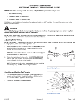
OPERATION
BREAK-IN PERIOD
1. After attaching header to combine or wind-
rower tractor for the first time, operate the
machine with reel drapers and sickle running
slowly for 5 minutes, watching and listening
FROM THE OPERATOR'S SEAT for binding or
interfering parts.
CAUTION: Before investigating an
unusual sound or attempting to
correct a problem, shut off engine,
engage parking brake and remove
key.
NOTE: Reel and side drapers will not operate until
oil flow fills the lines.
2. Change hydraulic oil filter(s) as recommended
in combine or windrower tractor Operator's
Manual.
3. Check hay conditioner chain tension after 2
hours for proper tension. See Maintenance/
Service section.
4. Adjust the tension of sickle drive belt(s) (A)
after a 5 hour run-in period. (See Maintenance/
Service section.) Continue to check the belt
tension periodically for the first 50 hours.
5. Tighten any loose hardware after the first
5 hours operation. See Specifications section
for recommended torques.
6. Tighten the four wobble box mounting bolts (B)
after the first 10 hours operation and every
100 hours thereafter. Torque to 200 ft.lbs. (270
N·m), starting with the side mounting bolts.
7. Change wobble box lubricant after the first
50 hours operation and every 1000 hours (or 3
years) thereafter. See Maintenance/Service
section.
CHECK SICKLE DRIVE BELT TENSION
(WINDROWER CONFIGURATION SHOWN)
A
TIGHTEN FOUR WOBBLE BOX
MOUNTING BOLTS
B
CHECK CONDITIONER CHAIN TENSION
/