Page is loading ...

1
INTRODUCTION
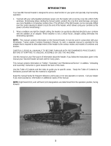
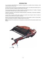
Your new MacDon Model 5020 Power-Tongue Windrower is designed to cut, condition and lay in
windrows, a wide variety of grasses and hay crops.
Use this manual as your first source of information about the machine. If you follow the instructions given
in this manual, your Windrower will work well for many years.
The manual contains instructions for "Safety", "Operation", and "Maintenance/Service". In addition,
"Unloading and Assembly" information is given towards the back of this book.
CAREFULLY READ ALL THE MATERIAL PROVIDED BEFORE ATTEMPTING TO UNLOAD,
ASSEMBLE, OR USE THE MACHINE.
Use the Table of Contents and the Index to guide you to specific areas. Study the Table of Contents to
familiarize yourself with how the material is organized.
Keep this manual handy for frequent reference and to pass on to new operators or owners. Call your
Dealer if you need assistance, information, or additional copies of this manual. A manual storage case is
provided on the primary drive shield at rear of main frame.
NOTE: Right hand (R/H) and left hand (L/H) designations are determined from the operator’s position,
facing forward.

2
TABLE OF CONTENTS
PAGE
INTRODUCTION ..................................................................................................................................1
SERIAL NUMBER LOCATION.............................................................................................................4
SAFETY
Safety Alert Symbol.........................................................................................................................5
Signal Words ...................................................................................................................................5
Safety Signs...................................................................................................................................6, 7
General Farm Safety .......................................................................................................................8
SPECIFICATIONS
Windrower..................................................................................................................................... 9,10
Tractor Requirements.....................................................................................................................10
Hardware Torque Specifications ....................................................................................................11
Hydraulic Fitting Torque Specifications..........................................................................................12
OPERATION
Your Responsibilities as an Owner/Operator .................................................................................13
To the New Operator......................................................................................................................13
Preparing the Tractor......................................................................................................................14
Preparing the Windrower................................................................................................................15
Attaching Windrower to Tractor...................................................................................................16,17
Detaching Windrower from Tractor.................................................................................................17
Break-In Period...............................................................................................................................18
Pre-Starting Checks: Annual ..........................................................................................................19
Pre-Starting Checks: Daily..............................................................................................................20
Operate Correctly ...........................................................................................................................21
Engaging the PTO..........................................................................................................................21
Lift Cylinder Stop (Raising and Lowering the Machine) .................................................................22
Steering...........................................................................................................................................23
180
° Turn........................................................................................................................................24
Turning Square Corners.................................................................................................................25
Operating Variables.....................................................................................................................25-33
Lean Bar Position .........................................................................................................................26
Ground Speed ..............................................................................................................................26
Reel Speed...................................................................................................................................27
Reel Position.............................................................................................................................. 27,28
Cutting Height (Skid Plates) .........................................................................................................29
Header Angle................................................................................................................................30
Header Flotation...........................................................................................................................31
Feed Pan / Rock Drop Tine Position............................................................................................31
Roll Gap........................................................................................................................................32
Forming Shields............................................................................................................................33
Rear Deflector.............................................................................................................................33
Haying Tips:................................................................................................................................. 34,35
Topsoil Moisture ...........................................................................................................................34
Climate and Topography ..............................................................................................................34
Windrow Characteristics...............................................................................................................35
Running Tractor Tire on Previously Cut Windrow........................................................................35
Raking and Tedding......................................................................................................................35
Chemical Drying Agents...............................................................................................................35
Unplugging the Windrower: Sickle..................................................................................................36
Unplugging the Windrower: Rolls...................................................................................................36
Shut-Down Procedure ....................................................................................................................37
Transporting the Windrower: Towing..............................................................................................37
Transporting the Windrower: Flatbed.............................................................................................38
Storage Procedure..........................................................................................................................39

3
TABLE OF CONTENTS
PAGE
MAINTENANCE/SERVICE
Service Procedures.........................................................................................................................39
Recommended Fluids and Lubricants............................................................................................40
Capacities of Enclosed Drives and Reservoir.................................................................................40
Bearing Installation .........................................................................................................................40
Closing Drive Shields......................................................................................................................41
Greasing the Windrower..............................................................................................................41-44
Center Link Ball Joints....................................................................................................................44
Spring Pivots...................................................................................................................................44
Hitch Pin Lock Nut ..........................................................................................................................44
Hydraulics................................................................................................................................... 45,46
System Safety...............................................................................................................................45
Hoses and Lines...........................................................................................................................45
Hydraulic Reservoir.................................................................................................................... 45,46
Hydraulic Oil Filter.........................................................................................................................46
Electrical........................................................................................................................................46
Sickle and Sickle Drive.............................................................................................................. 47-51
Sickle Lubrication..........................................................................................................................47
Sickle Sections..............................................................................................................................47
Sickle Removal.............................................................................................................................47
Sickle Head Needle Bearing Installation.......................................................................................48
Sickle Installation..........................................................................................................................48
Guards..........................................................................................................................................49
Excessive Breakage .....................................................................................................................49
Sickle Hold-Downs........................................................................................................................49
Sickle Drive Belt Tension..............................................................................................................50
Sickle Drive Belt Replacement .....................................................................................................50
Wobble Box Maintenance.............................................................................................................51
Reel and Reel Drive ......................................................................................................................52
Reel Drive Chain Lubrication........................................................................................................52
Reel Drive Chain Tension.............................................................................................................52
Reel Drive Belt Tension................................................................................................................52
Reel Tines.....................................................................................................................................52
Auger and Auger Drive..............................................................................................................53-55
Auger Position...............................................................................................................................53
Stripper Bars.................................................................................................................................54
Auger Drive Chain Lubrication......................................................................................................55
Auger Drive Chain Tension...........................................................................................................55
Rolls and Roll Drive................................................................................................................... 56,57
Roll Drive Chain Tension..............................................................................................................56
Roll Drive Chain Case Lubricant...................................................................................................56
Roll Timing....................................................................................................................................57
Roll Drive Chain Removal & Installation.................................................................................... 58,59
Wheels and Tires ..........................................................................................................................60
Wheel Bolts...................................................................................................................................60
Wheel Removal ............................................................................................................................60
Tire Inflation..................................................................................................................................60
Maintenance Schedule ...................................................................................................................61
Maintenance Record.......................................................................................................................62
TROUBLE SHOOTING.....................................................................................................................63-66
OPTIONS AND ATTACHMENTS
Additional Skid Plates .....................................................................................................................67
PTO Conversion Kits ......................................................................................................................67
Tall Crop Kit....................................................................................................................................67
Stub Guard Conversion Kit.............................................................................................................68
Hydraulic Header Angle Kits...........................................................................................................68
Reel Bat Replacement Kits.............................................................................................................68
UNLOADING & ASSEMBLY.............................................................................................................69-77
INDEX............................................................................................................................................... 78,79

4
SERIAL NUMBER LOCATIONS
Record the serial number in the space provided.
Windrower:
Serial number plate (A) is located on the side of
the left hand end frame.
Tongue:
Serial number plate (B) is located at rear of
tongue.
NOTE: When ordering parts and service, be sure
to give your dealer the complete and proper serial
number.
SERIAL PLATE LOCATION: WINDROWER
A
SERIAL PLATE LOCATION: TONGUE
B

5
SAFETY
SAFETY ALERT SYMBOL
This safety alert symbol indicates important safety messages in this
manual and on safety signs on the machine.
This symbol means:
ATTENTION!
BECOME ALERT!
YOUR SAFETY IS INVOLVED!
Carefully read and follow the safety message accompanying this symbol.
Why is SAFETY important to you?
· ACCIDENTS DISABLE AND KILL
3 BIG REASONS · ACCIDENTS COST
· ACCIDENTS CAN BE AVOIDED
SIGNAL WORDS
Note the use of the signal words DANGER, WARNING, and CAUTION with safety messages. The appropriate
signal word for each message has been selected using the following guidelines:
DANGER – Indicates an imminently hazardous situation that, if not avoided, will result in death or
serious injury.
WARNING – Indicates a potentially hazardous situation that, if not avoided, could result in death or
serious injury. It is also used to alert against unsafe practices.
CAUTION – Indicates a potentially hazardous situation that, if not avoided, may result in minor or
moderate injury. It is also used as a reminder of good safety practices.

6
SAFETY
SAFETY SIGNS
• The safety signs reproduced below appear on the windrower at the locations shown on page 7.
• Keep safety signs clean and legible at all times
• Replace safety signs that are missing or become illegible.
• If original parts on which a safety sign was installed are replaced, be sure the repair part also bears the
current safety sign.
• Safety signs are available from your Dealer Parts Department.
To install safety signs
:
1. Be sure the installation area is clean and dry.
2. Decide on the exact location before you remove the decal backing paper.
3. Remove the smaller portion of the split backing paper.
4. Place the sign in position and slowly peel back the remaining paper, smoothing the sign as it is applied.
5. Small air pockets can be smoothed out or pricked with a pin.
A - # 44611
B - # 32738
C - # 32009
D - # 28403
E - # 140311
F - # 44944
G - # 115100
H - # 140290
J - # 32008

7
SAFETY
SAFETY SIGN LOCATIONS
12’ UNIT 14’ & 16’ UNITS
PRIMARY DRIVE SHIELD
B
B
HEADER END FRAMES
B
B
D
D
TONGUE & FRAME BACK TUBE
F
G
H
J
MAIN FRAME
A
LEFT & RIGHT (14’ & 16’)
C
LEFT ONLY
E
LEFT & RIGHT
BACK SIDE OF
LEG FOR 12’
F
LEFT ONLY
LEFT & RIGHT (12’)
A

8
SAFETY
GENERAL SAFETY
The following are general farm safety
precautions that should be part of
your operating procedure for all
types of machinery.
1. Protect yourself.
When assembling, operating and servicing
machinery, wear all the protective clothing
and personal safety devices that COULD be
necessary for the job at hand. Don’t take
chances.
You may need:
· a hard hat.
· protective shoes with slip resistant soles.
· protective glasses or goggles.
· heavy gloves.
· wet weather gear.
· respirator or filter mask.
· hearing protection. Be aware that
prolonged exposure to loud noise can
cause impairment or loss of hearing.
Wearing a suitable hearing protective
device such as ear muffs (A) or ear plugs
(B) protects against objectionable or loud
noises.
2. Provide a first-aid
kit for use in case
of emergencies.
3. Keep a fire
extinguisher on the
machine. Be sure
the extinguisher is properly maintained and
be familiar with its proper use.
4. Keep young children away from machinery
at all times.
5. Be aware that accidents often happen when
the operator is tired or in a hurry to get
finished. Take the time to consider the
safest way. Never ignore warning signs of
fatigue.
6. Wear close-fitting clothing
and cover long hair. Never
wear dangling items such
as scarves or bracelets.
7. Keep hands, feet,
clothing and hair
away from moving
parts. Never attempt
to clear obstructions
or objects from a
machine while the
engine is running.
8. Keep all shields in
place. Never alter or remove safety
equipment. Make sure driveline guards can
rotate independently of the shaft and can
telescope freely.
9. Use only service and repair parts made or
approved by the equipment manufacturer.
Substituted parts may not meet strength,
design, or safety requirements.
10. Do not modify the machine. Unauthorized
modifications may impair the function
and/or safety and affect machine life.
11. Stop engine and remove key from ignition
before leaving operator's seat for any
reason. A child or even a pet could engage
an idling machine.
12. Keep the area used for
servicing machinery
clean and dry. Wet or
oily floors are slippery.
Wet spots can be
dangerous when
working with electrical
equipment. Be sure all
electrical outlets and
tools are properly grounded.
13. Use adequate light for the job at hand.
14. Keep machinery clean. Straw and chaff on a
hot engine are a fire hazard. Do not allow oil
or grease to accumulate on service
platforms, ladders or controls. Clean
machines before storage.
15. Never use gasoline, naphtha or any volatile
material for cleaning purposes. These
materials may be toxic and/or flammable.
16. When storing machinery, cover sharp or
extending components to prevent injury
from accidental contact.
A
B

9
SPECIFICATIONS
DIMENSIONS
12 FT. 14 FT. 16 FT.
Overall Width:
Transport Position 13.5 ft. (4103 mm) 15.5 ft. (4713 mm) 17.5 ft. (5323 mm)
Field Position 18.1 ft. (5531 mm) 21.1 ft. (6446 mm) 24.1 ft. (7360 mm)
Overall Length:
Transport Position 20.7 ft. (6320 mm) 22.1 ft. (6740 mm) 24.9 ft. (7573 mm)
Field Position 15.8 ft. (4816 mm) 16.3 ft. (4975 mm) 18.2 ft. (5557 mm)
Overall Height
Transport Position 6.2 ft. (1896 mm)
Field Position 6.2 ft. (1896 mm)
Weight 5900 lbs. (2675 kg) 6250 lbs. (2835 kg) 6623 lbs. (3005 kg)
CUTTERBAR
Cutterbar Width 12.25 ft. (3734 mm) 14.25 ft. (4343 mm) 16.25 ft. (4953 mm)
Cutting Height (on skids) 1.5 to 4 in. (38 to 100 mm)
at 8° guard angle
Guard (Header) Angle (adjustable) 6° to 11.5° below horizontal
Cutterbar Range 2.0 in. below ground to 21 in. above ground
at 8° guard angle (to guard tip) (-50 mm to +533 mm)
MAIN DRIVE
540 or 1000 RPM PTO tractor driven pump
to hydraulic motor driving primary shaft
Rear Countershaft Speed 1156 RPM *
SICKLE
Drive Type Belt driven wobble box (enclosed oil bath)
Speed 1560 strokes or 780 cycles per minute *
Stroke 3 in. (76 mm)
Sections Over-serrated, low shoulder
Guards Double heat treated, forged steel
REEL
Drive Type V-belt drive from R/H auger shaft
to chain final drive
Reel Type 5 bats (4 or 6 bats optional),
replaceable steel pick-up tines,
cam action, polymer tine tube bearings
Radius 22 in. (1560 mm) to finger tip
Speed 72 RPM as assembled / 59 RPM with
pulley exchange / 66 RPM optional *
NOTE: Specifications listed only under 14 ft. column are common to all sizes.
* All speeds are in no-load condition at rated tractor RPM.

10
SPECIFICATIONS
AUGER
12 FT. 14 FT. 16 FT.
Drive Type Chain final drive
Overload Protection Hydraulic motor
Auger Type 20 in. (508 mm) diameter
variable pitch, center feed
Auger Speed 245 RPM *
CONDITIONER ROLLS
Drive Type Drivelines from enclosed oil bath chain drive
Roll Type Helical intermeshing steel “V” bars
Roll Diameter 8.75 in. (222 mm)
Roll Length 93 in. (2360 mm)
Roll Speed 827 RPM *
WHEELS
Tread Width 119 in. (3030 mm) 143 in. (3640 mm) 143 in. (3640 mm)
Tires 31 x 13.5 - 15 NHS 8 ply Terra-Rib
Tire Pressure 30 psi (207 kPa)
MATERIAL DISCHARGE
Minimum Width 30 in. (760 mm)
Maximum Width 92 in. (2346 mm)
Rear Fluffing Shield Adjustable
OPERATING SPEED
Recommended Field Speed 5 mph (8 km/h)
Recommended Transport Speed 20 mph (30 km/h)
TRACTOR REQUIREMENTS
Minimum Power 60 hp (45 kw) 75 hp (56 kw) 90 hp (68 kw)
Drawbar Capacity Must Exceed 1300 lbs. (5785 N) 1030 lbs. (4580 N) 1100 lbs. (4895 N)
PTO 540 or 1000 RPM - ASAE standard location
Hydraulic Capacity 1750 psi (12000 kPa), two hydraulic circuits
* All speeds are in no-load condition at rated tractor RPM.
(SPECIFICATIONS AND DESIGN ARE SUBJECT TO CHANGE WITHOUT NOTICE OR OBLIGATION TO
REVISE UNITS PREVIOUSLY SOLD.)

11
TORQUE SPECIFICATIONS
CHECKING BOLT TORQUE
The tables shown below give correct torque values for various bolts and capscrews. Tighten all bolts to the
torques specified in chart unless otherwise noted throughout this manual. Check tightness of bolts periodically,
using bolt torque chart as a guide. Replace hardware with the same strength bolt.
ENGLISH TORQUE SPECIFICATION
NC Bolt Torque*
SAE 5 SAE 8
Bolt
Dia.
"A"
N·m [lb-ft] N·m [lb-ft]
1/4" 12 [9] 15 [11]
5/16" 24 [18] 34 [25]
3/8" 43 [32] 56 [41]
7/16" 68 [50] 95 [70]
1/2" 102 [75] 142 [105]
9/16" 149 [110] 202 [149]
5/8" 203 [150] 271 [200]
3/4"
359 [265]
495 [365]
7/8" 569 [420] 813 [600]
1" 867 [640] 1205 [890]
METRIC TORQUE SPECIFICATIONS
Bolt Torque*
8.8
10.9
Bolt
Dia.
"A"
N·m
[lb
-
ft]
N·m
[lb
-
ft]
M3
0.5
[.4]
1.8
[1.3]
M4
3
[2.2]
4.5
[3.3]
M5
6
[4]
9
[7]
M6
10
[7]
15
[11]
M8
25
[18]
35
[26]
M10
50
[37]
70
[52]
M12
90
[66]
125
[92]
M14
140
[103]
200
[148]
M16
225
[166]
310
[
229]
M20
435
[321]
610
[450]
M24
750
[553]
1050
[774]
M30
1495
[1103]
2100
[1550]
M36
2600
[1917]
3675
[2710]
Torque figures indicated above are valid for non-greased or non-oiled threads and heads unless otherwise
specified. Do not grease or oil bolts or capscrews unless specified in this manual. When using locking
elements, increase torque values by 5%.
* Torque value for bolts and capscrews are identified by their head markings.

12
TORQUE SPECIFICATIONS
TIGHTENING HYDRAULIC O-RING FITTINGS*
1. Inspect O-ring and seat for dirt or obvious
defects.
2. On angle fittings, back the lock nut off until
washer bottoms out at top of groove.
3. Hand tighten fitting until back up washer or
washer face (if straight fitting) bottoms on face
and O-ring is seated.
4. Position angle fittings by unscrewing no more
than one turn.
5. Tighten straight fittings to torque shown.
6. Tighten angle fittings to torque shown while
holding body of fitting with a wrench.
* The torque values shown are based on
lubricated connections as in reassembly
.
Torque Value*
Recommended
Turns to Tighten
(after finger
tightening)
Thread
Size
(in.)
Nut Size
Across
Flats
(in.)
N·m
[lb-ft]
Flats
Turns
3/8
1/2
8
[6]
2
1/3
7/16
9/16
12
[9]
2
1/3
1/2
5/8
16
[12]
2
1/3
9/16
11/16
24
[18]
2
1/3
3/4
7/8
46
[34]
2
1/3
7/8
1
62
[46]
1-1/2
1/4
1-1/16
1-1/4
102
[75]
1
1/6
1-3/16
1-3/8
122
[90]
1
1/6
1-5/16
1-1/2
142
[105]
3/4
1/8
1-5/8
1-7/8
190
[140]
3/4
1/8
1-7/8
2-1/8
217
[160]
1/2
1/12
TIGHTENING HYDRAULIC FLARE-TYPE
TUBE FITTINGS*
1. Check flare and flare seat for defects that
might cause leakage.
2. Align tube with fitting before tightening.
3. Lubricate connection and hand tighten swivel
nut until snug.
4. To prevent twisting the tube(s), use two
wrenches. Place one wrench on the connector
body and with the second tighten the swivel
nut to the torque shown.
* The torque values shown are based on
lubricated connections as in reassembly.
Torque Value*
Recommended
Turns to Tighten
(after finger
tightening)
Tube
Size
O.D.
(in.)
Nut Size
Across
Flats
(in.)
N·m
[lb-ft]
Flats
Turns
3/16
7/16
8
[6]
1
1/6
1/4
9/16
12
[9]
1
1/6
5/16
5/8
16
[12]
1
1/6
3/8
11/16
24
[18]
1
1/6
1/2
7/8
46
[34]
1
1/6
5/8
1
62
[46]
1
1/6
3/4
1-1/4
102
[75]
3/4
1/8
7/8
1-3/8
122
[90]
3/4
1/8

13
OPERATION
YOUR RESPONSIBILITIES AS AN OWNER/OPERATOR
CAUTION:
1. It is your responsibility to read and
understand this manual completely before
operating the windrower. Contact your
dealer if an instruction is not clear to you.
2. Follow all safety messages in the manual
and on safety signs on the machine.
3. Remember that YOU
are the key to safety.
Good safety practices protect you and the
people around you.
4. Before allowing anyone to operate the
windrower, for however short a time or
distance, make sure they have been
instructed in its safe and proper use.
5. Review the manual and all safety related
items with all operators annually.
6. Be alert for other operators not using
recommended procedures or not following
safety precautions. Correct these mistakes
immediately, before an accident occurs.
7. Do not modify the machine. Unauthorized
modifications may impair the function
and/or safety and affect machine life.
8. The safety information given in this manual
does not replace safety codes, insurance
needs, or laws governing your area. Be sure
your machine meets the standards set by
these regulations.
9. Ensure that the tractor is properly equipped
to safely operate the windrower. This may
include adding ballast according to Tractor
Operator’s Manual requirements for
attachments of this size and mass.
TO THE NEW OPERATOR
It’s natural for an operator to be anxious to get
started with a new machine. Please take the time
to familiarize yourself with the windrower by
reading the Operator’s Manual and safety signs
before attempting operation.

14
OPERATION
PREPARING THE TRACTOR
1. Select proper tractor size. The minimum power
required is: 12 ft. - 60 hp (45 kw)
14 ft. - 75 hp (56 kw)
16 ft. - 90 hp (68 kw)
Tractor drawbar capacity must exceed:
12 ft. – 1300 lb. (5785 N)
14 ft. – 1030 lb. (4580 N)
16 ft. – 1100 lb. (4895 N)
Also, minimum hydraulics required are 1750
psi (12000 kPa) pressure with double acting,
dual remote capability.
2. Adjust tractor drawbar to meet ASAE Standard
specifications as listed below. An improperly
located drawbar may affect header flotation
and guard angle.
(A) 14 in. (356 mm) for 540 rpm.
16 in. (406 mm) for 1000 rpm.
(B) 6 to 12 in. (152 to 305 mm) with 8 in.
(203 mm) recommended.
(C) 13 to 17 in. (330 to 432 mm) from ground
with 16 in. (406 mm) recommended.
3. Secure the drawbar so the hitch pinhole is
directly below the driveline.
NOTE: If the tractor has a three-point hitch,
raise the lower links as high as possible to
prevent damage.
4. Attach the drawbar extension (D) to the tractor
drawbar.
IMPORTANT: To prevent damage to the pump
and hose assembly, do not operate the
machine without the drawbar extension. Use
washers (E) as required depending on drawbar
thickness.
Tighten 5/8 nut (F) to 160 ft.lbs. (215 N·m)
torque.
Tighten 1 inch slotted nut (G) to 630 ft.lbs.
(850 N·m) torque. Further tighten nut (G) to
align slot with hole and install cotter pin.
Back off nuts (J) and turn in four bolts (K) until
snug against tractor drawbar. Tighten nuts (J)
to secure the position.
5. Use proper PTO speed (540 or 1000)
depending on windrower options.
6. Tractor must be equipped with a seven
terminal outlet (H) to supply power to the
windrower's warning lights.
ATTACH DRAWBAR EXTENSION
SEVEN TERMINAL ELECTRICAL OUTLET
H
STANDARD DRAWBAR SPECIFICATIONS

15
STAND TO ONE SIDE WHEN INFLATING TIRES
OPERATION
PREPARING THE WINDROWER
1. Check the tires and inflate if necessary.
Recommended pressure is 30 psi (207 kPa).
CAUTION: When inflating tires, use
a clip-on chuck and extension hose
long enough to allow you to stand
to one side and not facing the tire.
2. Check for proper assembly and adjustment
and make sure all bolts are tightened securely.
3. Check the tension of the reel drive belt and the
sickle drive belt. Adjust if required. See
Maintenance/Service section.
4. Lubricate the machine completely and check
the oil level of the sickle drive box. See
Maintenance/Service section.
5. Check hydraulic oil level at dipstick. Add oil if
required. See Maintenance/Service section.
6. Install quick coupler tips (matching the tractor
to be used) on the remote hydraulic hoses.
CHECK REEL DRIVE BELT TENSION
CHECK HYDRAULIC OIL LEVEL
CHECK SICKL
E DRIVE BELT TENSION,
AND DRIVE BOX LUBRICANT

16
OPERATION
ATTACHING WINDROWER TO TRACTOR
CAUTION: Shut off tractor, engage
parking brake and remove key before
working around hitch.
CAUTION: Never attach windrower to
tractor rear axle or three-point hitch
arms.
1. Using the jack, raise windrower tongue to clear
the hitch pin in drawbar extension. Position
tractor to align ball joint on tongue with hitch pin
and lower tongue. Secure with lock pin (A).
2. Route hitch chain from windrower through
chain support (B), around drawbar support and
lock hook (C) on chain.
IMPORTANT: Adjust chain length to remove all
slack except what is needed for turns.
3. Remove weight from jack. Pull pin securing
jack and move to storage position (D) on top of
frame tube.
4. NOTE: Pump attachment is easier if hitch is
angled to tractor, not straight on.
Slide the hydraulic pump assembly onto the
PTO shaft of the tractor. Adjust the torque arm
(E) so that it rests on the right side of the
drawbar.
IMPORTANT:
• Pump outlets must remain vertical. Loop the
torque arm chain (F) around the drawbar and
lock the chain in keyhole slot in torque arm
mounting plate.
• To prevent hose damage, route hoses through
guide (G) to provide proper hose arc as shown.
• Full engagement of PTO shaft into pump is
required to prevent damage to pump spline.
Pump should slide 2-1/2" (64 mm) onto shaft.
• The pump must never be keyed or fastened to
the PTO shaft. If the drawbar pin should
become disengaged, the pump must be free to
slip off.
ATTACH PUMP ASSEMBLY
G
F
E
SECURE HITCH PIN AND CHAIN
C
B
A
JACK STORAGE
D

17
OPERATION
ATTACHING WINDROWER TO TRACTOR
(cont’d)
5. Connect remote hydraulic hoses as follows:
a. Connect the two tongue swing hoses (H) so
that when the tractor control is moved forward,
the swing cylinder will extend, moving the wind-
rower to the right. When the tractor control
handle is moved back, the swing cylinder will
retract, moving the windrower to the left.
b. Connect the two lift cylinder hoses (J) so that
when the tractor control is moved back, the lift
cylinder will extend, raising the header. When
the tractor control is moved forward, the lift
cylinder will retract, lowering the header.
6. Connect the windrower wiring harness plug (K)
to outlet on tractor.
DETACHING WINDROWER FROM TRACTOR
CAUTION: To prevent accidental
movement of tractor, shut off engine,
engage parking brake, and remove
key.
To maintain stability, always lower the
machine completely. Block windrower wheels
before detaching from tractor.
Park machine on flat level surface with hitch at
an angle to tractor drawbar (to facilitate pump
detachment).
Move remote cylinder control valve lever back
and forth to relieve stored hydraulic pressure.
1. Pull pin securing jack and move to working
position (A) at front of tongue.
2. Lower jack to take weight off tractor drawbar.
3. Unlock torque arm chain from keyhole slot in
torque arm mounting plate. Remove hydraulic
pump assembly and store at (B).
4. Disconnect hydraulic hoses and electrical
harness. Store with ends off ground.
5. Remove hitch pin lock (C) and unhook chain
(D) from tractor. Wrap chain around windrower
tongue for storage. Raise windrower tongue
with jack to clear hitch pin.
6. Slowly drive tractor away from windrower.
CONNECT REMOTE HYDRAULICS
AND ELECTRICAL
H
J
K
MOVE JACK TO WORKING POSITION
A
STORE PUMP ASSEMBLY
B
REMOVE HITCH PIN LOCK AND CHAIN
C
D

18
OPERATION
BREAK-IN PERIOD
1. After attaching windrower to tractor for the first
time, operate the machine slowly for 5 minutes,
watching and listening FROM THE TRACTOR
SEAT for binding or interfering parts.
CAUTION: Before investigating an
unusual sound or attempting to
correct a problem, shut off tractor,
engage parking brake and remove key.
2. Check wheel bolt torque after 1 hour
operation
and periodically thereafter (at least every 100
hours). Torque to 120 ft.lbs. (160 N
⋅m).
3. Check sickle drive belt (A), auger primary drive
belt (H) and reel drive belt (G) after 5 hours
operation for initial stretch. Tighten as
necessary. (See Maintenance/Service section).
Continue to check the belts periodically for the
first 50 hours.
4. Check hitch pin nut (B) after 5 hours
operation
and every 50 hours thereafter. Torque to 350
ft.lbs. (475 N
⋅m).
5. Check hardware after 5 hours
operation.
Tighten as necessary. See Specifications
section for recommended torques.
6. Tighten the four wobble box mounting bolts (C)
after 10 hours
operation and every 100 hours
thereafter. Torque to 200 ft.lbs. (270 N
⋅m),
starting with the side mounting bolts.
7. Check reel drive chain (D), auger drive chain
(E) and roll drive chain (F) after 10 hours
operation for proper tension and lubrication.
See Maintenance/Service section.
CONTINUED NEXT PAGE…..
CHECK SICKLE DRIVE BELT AND
AUGER DRIVE BELT & CHAIN TENSION
A
E
H
CHECK HITCH PIN LOCK NUT
B
CHECK WOBBLE BOX MOUNTING BOLTS
C
CHECK ROLL DRIVE CHAIN TENSION
F
D
G
CHECK REEL DRIVE BELT & CHAIN

19
OPERATION
BREAK-IN PERIOD
(continued)
8. Change wobble box lubricant after 50 hours
operation and every 1000 hours (or 3 years) thereafter. See
Maintenance/Service section.
9. Change hydraulic oil filter after 100 hours
operation and every 250 hours thereafter. See Hydraulics in
Maintenance/Service section.
10. Until you become familiar with the sound and feel of your new windrower, be extra alert and attentive.
PRE-STARTING CHECKS
Do the following at the start of each operating
season:
CAUTION:
1. Review the Operator’s Manual to refresh
your memory on safety and operating
recommendations.
2. Review all safety signs and other decals on
the windrower and note hazard areas.
3. Be sure all shields and guards are properly
installed and secured. Never alter or
remove safety equipment.
4. Be sure you understand and have practiced
safe use of all controls. Know the capacity
and operating characteristics of the
machine.
5. Check the first aid kit and fire extinguisher.
Know where they are and how to use them.
Also:
6. Adjust tension on drive belts. See
Maintenance/ Service section.
7. Perform all annual maintenance. See
Maintenance/ Service section.

20
OPERATION
PRE-STARTING CHECKS
Do the following each day before start-up:
CAUTION:
1. Clear the area of other persons, pets etc.
Keep children away from machinery. Walk
around the windrower to be sure no one is
under, on or close to it.
2. Remove foreign objects from the machine
and surrounding area.
3. Wear close fitting clothing and protective
shoes with slip resistant soles.
As well, carry with you any protective
clothing and personal safety devices that
COULD be necessary through the day.
Don’t take chances.
You may need:
- a hard hat
- protective glasses or goggles
- heavy gloves
- respirator or filter mask
- wet weather gear.
4. Protect against noise. Wear a suitable
hearing protective device such as ear muffs
or ear plugs to protect against
objectionable or uncomfortable loud
noises.
5. Check the machine for leaks or any parts
that are missing, broken, or not working
correctly.
NOTE: Use proper procedure when
searching for pressurized fluid leaks. See
"Hydraulics" in Maintenance/Service
section.
6. Be sure tractor and windrower are properly
attached, all controls are in neutral and
tractor brake is engaged.
7. Clean all lights and reflective surfaces on
the machine. Check lights for proper
operation.
8. Perform all Daily maintenance. See
Maintenance/Service section.
PROTECT YOURSELF
PROTECT AGAINST NOISE
/