Step One: Plan your setup
An AccelePort Xe adapter can be set up in a variety of ways. Before you
start your installation, be sure of the following:
Number of components.
You can connect up to four peripherals to an
AccelePort
4e and up to eight peripherals to an
AccelePort
8e host
adapter.
Location of components.
You can locate peripherals a distance from
the adapter, but you must be sure that the cables you use to make the
connection are properly constructed. Cable lengths of up to 4000 feet
are permissible with the EIA-422 interface. To achieve the greatest
reliability over distance, cables should be:
• Shielded, twisted pair cables.
• Grounded at both ends of the cable.
• Routed away from noise sources such as generators, motors and
fluorescent lights.
Cable Connections.
Before beginning the installation, be sure that you
have a cable for each peripheral that you will be attaching to the host
adapter. The connector type that you need at either end of the periph-
eral cable depends on the type of Digi cable assembly that you use
and the connector on the peripheral.
Digi cable assemblies are available with DB-9 or DB-25 connectors.
You will need to be sure that you have cables of the correct length
and with the right connectors to properly attach the devices you want
to use.
Additional information about the AccelePort 4e and 8e, such as specifica-
tions and cabling details, is provided on the CD-ROM that is packaged
with the host adapter.
Step Two: Install the Xe ISA host adapter
Before installing the Xe host adapter, you should do the following:
• Check system resources for a free I/O port address. The Xe adapter
uses four bytes of address space on the I/O bus of the computer into
which you are installing it.
• Wear an ESD wrist strap to ground yourself while handling the
adapter. If one is not available, discharge static electricity from your
body by touching an unpainted metal surface, such as the computer’s
chassis, prior to handling the adapter.
• Record the adapter serial number, which will enable Digi to provide
you with better service, should the need arise. The serial number label
has this general format:
S/N: (S) XXX XXXXX
• Unplug power from the PC.
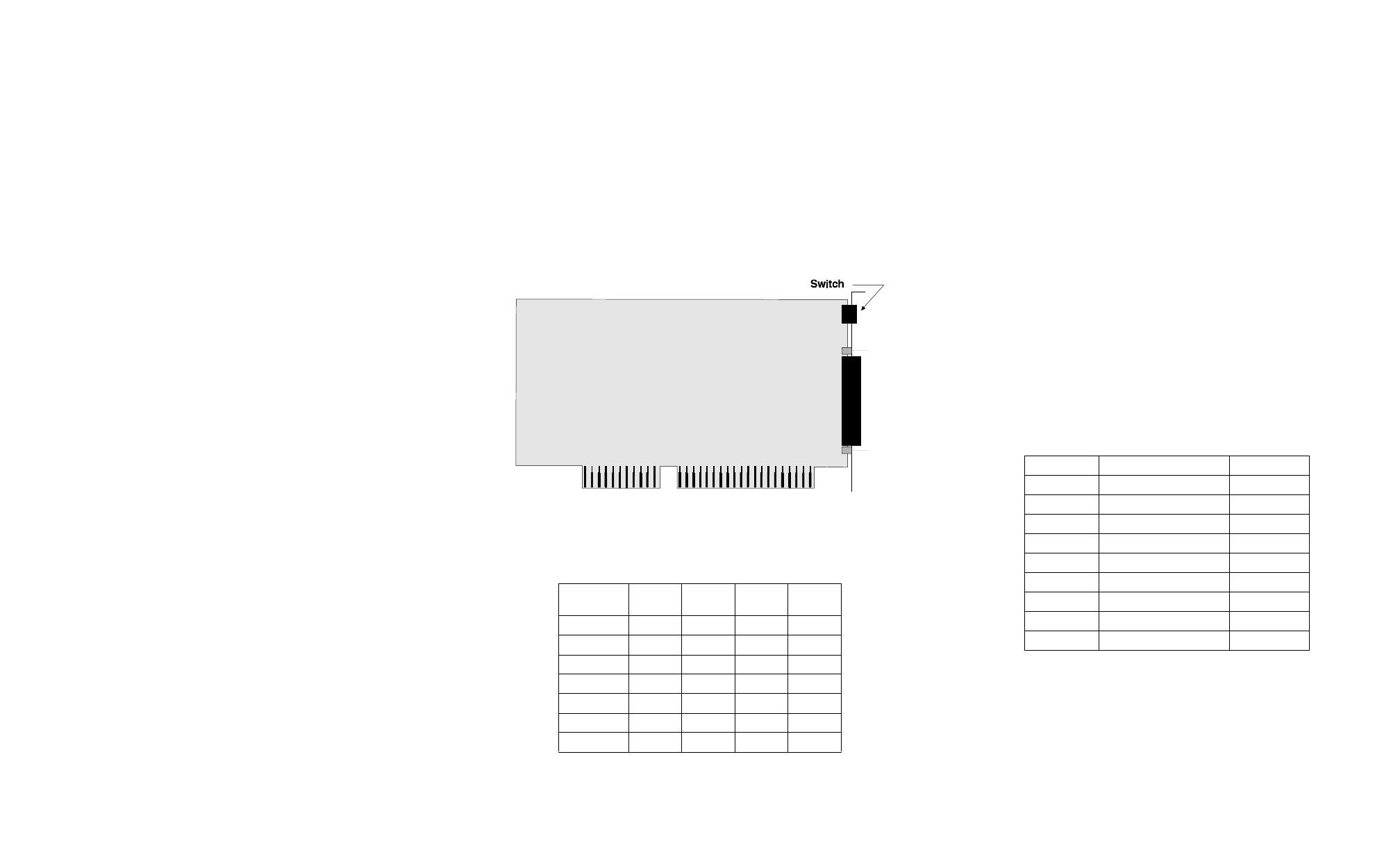
Figure 20.
Xe ISA host adapter
1. Set the I/O port address of the adapter to one of the following
addresses using the DIP switch at the location indicated in Figure 20:
2. Remove the computer’s cover.
3. Locate an available ISA slot in your computer and remove the slot
plate.
4. Insert the adapter into the slot and screw the endplate to the computer
chassis. The endplate must be screwed into the computer chassis to
remain in compliance with Part 15 of FCC rules.
5. Replace the computer’s cover.
6. Attach the 78-pin end of a Digi cable assembly to the connector on
the adapter.
Step Three: Install peripheral cabling
You can connect any standard EIA-422 device to be controlled by appli-
cations on the computer, to an AccelePort Xe host adapter by installing a
cable between the peripheral and the Digi cable assembly.
On the peripheral end of the cable, the connector you use depends on the
requirements of the peripheral. The other end of the cable must fit either a
DB-9 or DB-25 connector, depending on the Digi cable assembly you
have.
The pin assignments for each type of connector used on Digi’s cable
assemblies are as follows:
DB-25 Pin Assignments
I/O
address
1234
100-103h up up down down
110-113h up down up down
120-123h up down down down
200-203h down up up down
220-223h down up down down
300-303h down down up down
320-323h down down down down
Signal Description Pin
GND Chassis Ground 1, 7 *
TxD A (+) Transmitted Data (+) 2
TxD B (-) Transmitted Data (-) 14
RxD A (+) Received Data (+) 3
RXD B (-) Received Data (-) 16
RTS A (+) Request To Send (+) 4
RTS B (-) Request To Send (-) 19
CTS A (+) Clear To Send (+) 5
CTS B (-) Clear To Send (-) 13
* Chassis Ground is also available on the
connector shell


