Page is loading ...

4211-190 07/13/18
DIAGRAM 1
AK Chromatherapy-White Light Kit
Installation and Operating Instructions
The AK Chromatherapy-White LED Kit is designed to be used in any steam bath or shower enclosure. The LED lights
should be mounted in the ceiling of the room, the transformer and controller should be in a convenient dry location. The
On/Off switch is used to change the LED light colors and patterns.
Installation Overview
Chroma
Controller
Control
Switch
Light
Assemblies
Power
Transformer
General Installation
Determine locations suitable for mounting the Chromatherapy-White light system’s components:
• The control switch should be mounted where it is convenient to the user. It is used to momentarily turn the LED lights
off then on again in order to change their colors and patterns. The control switch may be mounted inside or outside
the steam room. A 25' cable is provided to connect the switch to the Controller.
• The LED light assemblies are to be mounted in the ceiling of the steam room. The LED’s 8' power wires will connect
to the controller. Note: two LED lights are supplied. Up to 5 additional lights (7 total) may be added.
• The 120VAC to 12VAC power transformer should be connected to a switched wall outlet. A 6' power cord with a
standard 15A 3-prong plug is attached to the transformer and 8’ of low voltage wires are attached to the transformer.
The low voltage wires are to be connected to the Chroma Controller. Whenever the wall outlet is turned on, the LED
lights will light.
• The controller should be mounted on a wall in an easily accessible location convenient to the other components.
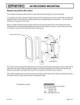
Install the Power Transformer
• The transformer should be connected to a switched wall outlet.
• Whenever the outlet is switched on, the LED lights will turn on.
• A 6 foot power cord with an attached NEMA-15 plug is supplied
as part of the transformer.
• The transformer may be attached to the wall using its integral
mounting tabs.
12 VAC
LIGHT1
LIGHT2
CONTROL

4211-190 07/13/18
AK Chromatherapy-White Light Kit
Installation and Operating Instructions
page 2
12 VAC
LIGHT1
LIGHT2
CONTROL
Install the Chroma Controller (Diagrams 2 & 3)
The Chroma Controller should be mounted on a wall
within reach of the transformer’s 8' low voltage wires.
These wires may be lengthened by adding 60°C 18 AWG
copper wires.
• Remove the controller’s front cover by pulling out slightly
on the sides to unsnap it. Mount the controller to the wall
using two screws through the mounting holes in the
controller’s base.
• Run the power transformer’s low voltage wires to the
controller and through the fi rst hole in the controller’s
end. Insert the stripped wire ends into the terminal
block’s 12VAC positions while pressing the terminal
block tabs with a small tip screw driver. Release the
tabs to secure the wires.
• Place a strain relief (provided, not shown) around the
cable close to the controller and squeeze it closed
with pliers while pushing it into the hole to secure the
cable.
• Secure the wires to the wall as needed to prevent stress
or other risks of damage.
Install the Display Control Switch (Diagrams 4 & 5)
The low voltage control switch can be mounted directly to
a fi nished wall either inside or outside the steam room.
• Rough-in the switch cable (this cable has a plug on each
end similar to a telephone’s). Using a 1-3/4" hole saw,
drill a hole in the fi nished wall where the switch is to be
mounted.
• Locate the switch cable, pull it out through the 1-3/4"
hole and plug the cable into the connector in the back of
the control switch housing.
• Run a bead of 100% silicone caulk around the perimeter
on the back of the control switch housing. Insert the
switch into the 1-3/4" hole and tape in place until the
silicone dries.
• Using the methods previously listed, connect the other
end of the switch cable to the Chroma Controller’s
CONTROL jack and secure the cable.
Install the Light Assembly (Diagrams 6, 7 & 8)
• Determine placement of each light.
• Drill a 2-5/8" hole for each lens assembly
• Insert the lens housing through the hole with the silicone
gasket on the room side of the ceiling and hand tighten
nut against other side. If the ceiling is too thick to use the
nut, silicone the light assembly into place using 100%
silicone sealant. (See Diagram 6)
DIAGRAM 3
DIAGRAM 2
DIAGRAM 4
12 VAC
LIGHT1
LIGHT2
CONTROL
DIAGRAM 5
Single Position
Rough-in Box
(optional)
Tile up to 1-3/4"
diameter hole in
fi nished wall
Apply Sealant
100% Silicone Caulk
Mount to wall using
two screws

4211-190 07/13/18
AK Chromatherapy-White Light Kit
Installation and Operating Instructions
page 3
Install the Light Assembly (continued)
• Insert the LED assembly into the refl ector and plug
assembly into the LED socket.
• Screw the refl ector onto the back of the lens housing,
then twist-n-lock the LED socket into refl ector.
• Run the wires from the light assembly to the controller
and through the second hole in the controller’s end.
Connect the wires to the terminals block’s L1 positions
and install a strain relief and secure the cord in the
same manner used for the transformer wires. The
controller’s L2 connections are supplied for your
convenience when connecting the second light.
Note: To change an LED assembly after installation, fi rst
unplug the power transformer then follow the instructions
engraved on the tool set. Insert the two tabs on the outer
tool into the two notches on the outside edge of the light
body and insert the ends of the center tool into the holes
in the lens. Hold the outer tool to keep the light body from
turning while turning the center tool to remove the lens.
Additional Light Assemblies
Up to fi ve additional LED light assemblies may be added
by connecting them in parallel with the other lights. Con-
nect them to the controller or by splicing their wires in par-
allel with the fi rst light’s wires. Order the Single Lamp Kit,
Amerec part number 9223-112.
DIAGRAM 7
DIAGRAM 6
Nut
LED Assembly
LED socket
Refl ector
Lens Housing
Ceiling
Gasket, far side
LED Assembly
LED socket
Operation
The lights are low power LED assemblies with built in
intelligence providing an array of pre-programmed light
displays and easy synchronization of multiple lights. The
last display selected will be active the next time the lights are turned on.
• Whenever the transformer’s switched outlet is turned on, the lights are on.
• To synchronize lights, such as after adding or replacing a light, turn the lights on then turn them off again for 6 to 8
seconds, then turn them on again. When the lights turn on again, they will blink a few times then all the lights will be
reset to the initial display.
• To change light displays, turn the lights off for 1 to 3 seconds then turn them on again. Repeat until your preferred
display is lit.
Description of displays (in order):
• Bright White
• Aqua Blue - a light blue/green mix.
• Soothing Violet - a light blue/red.
• Ocean Blue - pure blue.
• Majestic Gold - a red/green mix.
• Shamrock Green - pure green.
• Fiery Red - pure red.
• Chameleon Mode - a slow fade through all the colors in a repeating sequence.
• Party Mode - fast, random changes through all the colors.
DIAGRAM 8
Lens Housing
Outer Tool
Center Lens
Center Tool

4211-190 07/13/18
AK Chromatherapy-White Light Kit
Installation and Operating Instructions
page 4
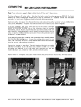
3
2
1
1
2
3
4
5
6
7
8
9
10
Provided
1
1
1
2
2
1
1
1
1
1
Part #
8855-145
3164-51
5268-12
3160-77
3160-72
9140-101
5304-031
4211-136
4000-23
4980-03
Description
Chroma Controller
Transformer, 120VAC-12VAC
Light Socket and Wires, 8'
Light, 12 LED, Chroma and White
Lens Assembly
Switch, Display Control
Cable, 3 Conductor, 25'
Instructions, Rough In
Rough In Bracket
Rough In Insert
Item
12 VAC
LIGHT1
LIGHT2
CONTROL
ON/OFF
SWITCH
CONTROLLER
12VAC
LIGHTS
120VAC
Contact Technical Support for additional/replacement parts.
1-800-363-0251
4
5
P.O Box 2258 Woodinville, WA 98072
800-363-0251 Fax: 425-951-1130
email address: [email protected]
9223-111 Additional Chroma-White Light Kit
/