Aquatic SUNSET Installation guide

Type
Installation guide
OWNER’S MANUAL &
INSTALLATION GUIDE
Estate Air-Whirlpool
INSTALLER: This booklet must be given to the product owner.
Read all instructions before proceeding. All specifications
are ±
3
8’’ and are subject to change without notice.
Dimensions listed in inches.
Model #
Purchase Date
Serial #
Distributor
2 Aquatic
Estate Air-Whirlpool Owner's Manual & Installation Guide
PRODUCT WARRANTY REGISTRATION INFORMATION 3
INSTRUCTIONS PERTAINING TO A RISK OF FIRE, ELECTRIC SHOCK,
OR INJURY TO PERSONS 4 – 5
USER INFORMATION 6
FCC INFORMATION 6
AQUATIC LIMITED LIFETIME WARRANTY 7
INSTALLATION INSTRUCTIONS
Pre-Installation Procedures 8
Structural Preparation 9 – 10
Factory Installed Tile Flange 10
Integrally Skirted Models 10 – 11
Framing Diagrams 12
Deck Cutouts 13
Plumbing 14
Electrical Installation 14 – 15
Final System Test & Clean-Up 16
OPERATION
Bathside Control Systems 17 – 18
Jet Operations 19
To Replace LED Light 20
TUB CARE
Maintenance 21 – 22
Repair 22
WATER QUALITY
Chemical and Water Quality 23 – 24
TROUBLESHOOTING GUIDE 25
REPLACEMENT PARTS LIST 26
REPLACEMENT PARTS MAP 27 – 28
TABLE OF CONTENTS
Aquatic 3
Estate Air-Whirlpool Owner’s Manual & Installation Guide
Thank you for choosing an Aquatic bath. You have chosen one of the finest bath products in the industry! Aquatic supports
your purchase with strong commitments to quality and customer satisfaction.
Please read and follow all of the instructions contained in this Owner’s Manual before installing, operating or maintaining
your bath. In addition, you should continually refer to these instructions during the life of your air-whirlpool bath. Failure to
comply with these instructions may invalidate your warranty. If you have any questions concerning installation, operation,
maintenance or any other aspect of your Aquatic bath, please contact:
AQUATIC CUSTOMER SERVICE CENTER: (800) 945-2726
(The Troubleshooting Guide on page 25 may be helpful in answering some of your questions.)
NOTE: The installation and service of your air-whirlpool
should be performed ONLY by a qualified electrician and plumber.
AQUATIC
Product Warranty Registration Information
IMPORTANT!
IMPORTANT!
To activate Product Warranty please register with Aquatic.
Your product warranty must be registered and confirmed with Aquatic through
the Serial Number on your unit. To register, please contact Aquatic.
(800) 945--2726 • www.aquaticbath.com/register
This product MUST BE WATER-TESTED and inspected prior to installation
or warranty will be voided. See page 8 for instructions.
PLEASE CHECK ENTIRE UNIT FOR ANY DAMAGE.
If it appears damaged, contact your Aquatic Distributor immediately.
Aquatic warranty does not cover damage that occurs in transit.
IMPORTANT!
MODEL & SERIAL NUMBER LOCATION
The tub model and serial numbers are located above the
pump area on the backside of the bathtub. An access
panel should be placed by the installer at this location.
Customer Service: 800.945.2726 • aquaticbath.com
4 Aquatic
Estate Air-Whirlpool Owner's Manual & Installation Guide
WARNING
Electrical Shock Hazard
Plug into a grounded 3-prong
outlet.
Do not remove ground prong.
Do not use an adapter.
Do not use an extension cord.
Failure to follow these
instructions can result in
death, fire, or electrical shock.
INSTRUCTIONS PERTAINING TO A RISK OF FIRE,
ELECTRIC SHOCK, OR INJURY TO PERSONS
WARNING: When using this unit, basic precautions should always be followed. Failure to follow these instructions could
result in personal injury, electric shock, or fire.
READ AND FOLLOW ALL INSTRUCTIONS:
WARNING: Risk of lethal electric shock. To reduce risk of electric shock, connect only to circuits protected by a
Ground-Fault Circuit-Interrupter (GFCI) or Residual Current Device (RCD).
DANGER: To reduce the risk of injury, do not permit children to use this unit unless they are closely supervised at
all times.
Use this unit only for its intended use as described in this manual. Do not use additional attachments and/or
equipment not recommended by the manufacturer.
Never drop or insert any object into any opening.
The unit must be connected only to a supply circuit that is protected
by a Ground-Fault Circuit-Interrupter (GFCI). Such a GFCI should be
provided by the installer and should be tested on a routine basis. To
test the GFCI, push the test button. The GFCI should interrupt power.
Push the reset button. Power should be restored. If the GFCI fails to
operate in this manner, there is a ground current flowing, indicating the
possibility of an electric shock. Do not use this unit. Disconnect the unit
and have the problem corrected by a qualified service representative
before using.
To reduce the risk of injury, enter and exit the bath slowly.
This product is intended for indoor use only. Installing this unit outdoors
could cause personal injury and will void your warranty.
SAVE THESE INSTRUCTIONS.
Your safety and the safety of
others are very important.
We have provided many important
safety messages in this manual and
on your appliance. Always read
and obey all safety messages.
This is the safety alert
symbol. This symbol
alerts you to potential
hazards that can kill or
hurt you and others.
All safety messages will follow the
safety alert symbol and either the
word “DANGER” or “WARNING.”
These words mean:
DANGER
You can be killed or seriously
injured if you don’t immediately
follow instructions.
WARNING
All safety messages will tell you
what the potential hazard is, tell you
how to reduce the chance of injury,
and tell you what can happen if the
instructions are not followed.
CALIFORNIA PROP. 65
WARNING: This product
can expose you to chemicals
including styrene and sty-
rene compounds, which are known
to the State of California to cause
cancer and birth defects or other
reproductive harm. For more informa-
tion go to www.p65warnings.ca.gov
Aquatic 5
Estate Air-Whirlpool Owner’s Manual & Installation Guide
INSTRUCTIONS PERTAINING TO A RISK OF FIRE,
ELECTRIC SHOCK, OR INJURY TO PERSONS
Before taking your first air-whirlpool bath, be sure that you are familiar with all the controls and switches [See
BATHSIDE CONTROL SYSTEMS starting on page 17.] and that the unit is operating properly. [See INSTRUCTIONS start-
ing on page 4.]
1. The water in a bath tub should never exceed 40° C (104º F). Water temperature between 38º C (100º F) and 40º C
(104º F) are considered safe for a healthy adult. Bathing time should be limited to approximately 30 minutes, followed
by a shower to cool down. Longer exposure may result in hyperthermia. The symptoms of this condition are nausea,
dizziness and fainting, which can be fatal. Lower water temperatures are recommended for extended use (exceeding
10-15 minutes) and for young children.
2. If you will not be operating the bath system during your bath, you may fill the bathtub to any comfortable level.
However, if you will operate the system, you must fill the bathtub as described in the section entitled FINAL SYSTEM
TEST & CLEAN-UP on page 16. This will assure proper operation of the system.
3. A few important bathing “DONT’S”-
DO NOT operate the air-whirlpool bath system if:
The bathtub isn’t filled to required levels above air channels and/or jets.
You’re pregnant (until you’ve consulted your doctor).
You’re taking medications or drugs that may make you drowsy.
You’re drinking any form of alcohol.
You’ve just had a meal. Wait for 30 minutes after eating.
There is a child in the bathtub who may be left unattended at any time. Never allow small children to remain
unattended in any bathtub.
There are any small objects in the bathtub. The air-whirlpool action can move small objects at high speeds,
causing pain and possible injury.
You’re smoking. The heat of burning tobacco can damage the bathtub surface. Keep tobacco products and
ashtrays away from the bathtub.
You have problems with your immunity system (until you have consulted your doctor).
Never operate electrical appliances (television, hair dryer, radio, telephone, etc.) inside or within five feet (5') of
the bath.
You are using additional attachments and/or equipment not recommended by the manufacturer.
You have a medical history of heart disease, low or high blood pressure,
circulatory system problems, or diabetes, consult with a physician before using an air-whirlpool.
You are under the influence of drugs, anticoagulants, stimulants, antihistamines, vasoconstrictors, vasodilators,
hypnotics, narcotics, or tranquilizers.
6 Aquatic
Estate Air-Whirlpool Owner's Manual & Installation Guide
The air-whirlpool action may cause even small amounts of bubble bath or shampoo to foam excessively. Exercise modera-
tion in experimenting with different soap products.
No servicing of this product should be done by the user. There are no user serviceable parts. All controls are located in
the control recesses on the lip of the tub. These are the only controls that should be used by the consumer. Do not change
or alter any of these controls under any circumstances.
Motors are self-lubricating -- No lubrication required.
This equipment generates and uses radio frequency energy and if not installed and used properly, that
is, in strict accordance with the manufacturers instruction, may cause interference to radio and television
reception. It has been type tested and found to comply with the limits for a class B computing device
in accordance with the specifications in subpart J of part 15 of the FCC rules, which are designed to
provide reasonable protection against such interference in a residential installation. However, there is
no guarantee that interference will not occur in a particular installation. If this equipment does cause
interference, which can be determined by turning the equipment on and off, the user is encouraged
to try to correct the interference by one or more of the following measures:
Reorient the receiving antenna.
Relocate the receiver with respect to the bath tub.
Move the receiver away from the bath.
Plug the receiver into a different outlet so that the receiver and bath are on different branch circuits.
If necessary, the user should consult the dealer or an experienced radio/television technician
for additional suggestions.
The user may find the following booklet prepared by the FCC helpful: “How To Identify and
Resolve Radio-TV Interference Problems.” It is available from the U.S. Government Printing
Office, Washington, DC 20402, Stock No. 004-000-00345-4.
WHIRLPOOL USER INFORMATION
PLEASE NOTE:
FCC CONSUMER INFORMATION
Electrical Installation Information Listed on pages 14 and 15.
Aquatic 7
Estate Air-Whirlpool Owner’s Manual & Installation Guide
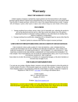
Aquatic Limited Lifetime Warranty
FOR ESTATE SERIES
Limited Warranty For Original Consumer For Household Usage
WHAT PRODUCTS ARE COVERED
Structures and surface finishes on Whirlpools (“Whirlpools”), Air Baths (“air baths”) and Soaking Tubs (“Tubs”), and their support equipment, components, attachments,
controls and plumbing equipment. Different warranty periods apply to specific components.
Warranty Periods for Specific Components
LIFETIME WARRANTY FOR WHIRLPOOL/AIR BATH/TUB SHELL, PUMP AND BLOWER
Aquatic extends to the original consumer purchaser of the acrylic, fiberglass reinforced shell, a non-transferable lifetime warranty that the shell will retain its structural
integrity and configuration and be free of water loss due to a defect in the tub shell. The warranty covers the tub shell and the factory installed pump and blower
against defects in material or workmanship. This warranty does not apply to all other components (attachments to the acrylic, fiberglass reinforced shell, such as
plumbing, fittings and other apparatus) because these pieces are covered below under a 2 Year Warranty.
LIFETIME SURFACE WARRANTY FOR FACE OF WHIRLPOOL/AIR BATH/TUB
The interior surface is warranted against fading, blistering, cracking and delamination due to defects in the surface materials for life. This surface warranty extends
to defects due to surface material mixing or molding. This surface warranty does not apply to fading, cracking, delamination or blistering due to excessive wear,
sun fading or scouring due to cleaning.
2 YEAR EQUIPMENT WARRANTY FOR SUPPORT EQUIPMENT, COMPONENTS, CONTROLS & PLUMBING EQUIPMENT
All support equipment; components, controls and plumbing equipment are warranted for 2 years from date of purchase, but not more than 3 years from date of
manufacture, against defects in workmanship and materials. Light bulbs, fuses and pillows are not included in this two-year period. However, these accessories are
warranted to be free from defects in materials and workmanship at the time of delivery to the original purchaser. Limited labor is covered for 2 years from purchase,
but never more than 3 years from date of manufacture, for limited labor on the support equipment, controls, and plumbing.
EXCLUSIVE REMEDY
Aquatic will, at its option, repair or replace (without removal or installation) the affected components of any defective Unit or System; repair or replace (without removal
or installation) the entire defective Unit or System; or refund the then-current list price of the Whirlpool, Air Bath, or Tub. In all cases, a reasonable time period must
be allowed for warranty repairs to be completed.
WHAT YOU MUST DO
In order to make a claim under these warranties:
1. You must be the original consumer purchaser of the Whirlpool, Air Bath, or Tub.
2. You must promptly notify us within the warranty period of any defect and provide us with any substantiation that we may reasonably request.
Contact Warranty Services: 800.945.2726 • aquaticbath.com.
3. The Whirlpools, Air Baths, and Tubs must have been installed and maintained in accordance with good industry practice and the specific Aquatic directions
contained in the Owner’s Manual and Installation Guide.
EXCLUSIONS
These warranties do not extend to or do not cover defects caused by:
1. Shipping damage by carriers or installation errors.
2. Accident, acts of God, abuse or misuse.
3. Unreasonable use (including any use for non-bathing purposes or failure to provide reasonable and necessary maintenance as specified in Aquatic Owner’s
Manual and Installation Guide supplied with the Whirlpool, Air Bath or Tub).
4. Any alteration, customization, or modification of the Whirlpool/Air Bath/Tub or its components.
LIMITATIONS
1. Aquatic whirlpools and tubs sold for industrial, commercial and hotel use are warranted for two years, but not more than 3 years from date of manufacture,
with a 2 year limited warranty that the shell will retain its structural integrity and configuration and be free of water loss due to a defect in the tub. The interior
surface/face of the whirlpool/air bath/tub is warranted against fading, blistering, cracking and delamination due to defects in the surface materials for 2
years as well. All support equipment, components, controls and plumbing equipment and limited labor on the support equipment, controls, or plumbing are
warranted for 1 year from date of purchase, but not more than 2 years from date of manufacture. Pump seals, “O” rings, light bulbs, fuses and pillows are not
included in this two-year period. However, these accessories are warranted to be free from defects in materials and workmanship at the time of delivery to
the original purchaser.
2. In all cases, Aquatic reserves the right to fully satisfy its obligations under the Limited Warranties by refunding the then-current list price of the defective
Whirlpool, Air Bath, or Tub (or, if the Whirlpool, Air Bath, or Tub has been discontinued, of the most nearly comparable current product).
3. THESE WARRANTIES ARE NON-TRANSFERABLE TO ANY OTHER PURCHASER OR PARTY OTHER THAN THE ORIGINAL CONSUMER. NO OTHER AGENT
OR PARTY CAN GIVE ANY OTHER WARRANTY OR PROMISE. THIS IS THE SOLE WARRANTY FOR YOUR Aquatic PRODUCT.
4. Aquatic will not cover any installation or reinstallation costs related to this warranty, except under the limited labor allowance under the 2 Year Equipment
Warranty above.
GENERAL
This warranty gives you specific legal rights; you may also have other rights, which vary from state to state. THE DURATION OF ANY IMPLIED WARRANTIES,
INCLUDING THE IMPLIED WARRANTIES OF MERCHANTABILITY AND FITNESS FOR A PARTICULAR PURPOSE, ARE LIMITED TO THE DURATION OF THE EXPRESS
WARRANTIES HEREIN. Aquatic EXPRESSLY EXCLUDES INCIDENTAL AND CONSEQUENTIAL DAMAGES, TO INCLUDE LOSS OF TIME, INCONVENIENCE, OR
LOSS OF USE OF RESIDENCE, FOR ANY BREACH OF THE EXPRESS OR IMPLIED WARRANTY, INCLUDING THE IMPLIED WARRANTIES OF MERCHANTABILITY
OR FITNESS FOR A PARTICULAR PURPOSE.
SOME STATES DO NOT ALLOW ANY LIMITATION ON HOW LONG AN IMPLIED WARRANTY LASTS, OR THE EXCLUSION OR LIMITATION OF INCIDENTAL
OR CONSEQUENTIAL DAMAGES; SO THE ABOVE EXCLUSION MAY NOT APPLY TO YOU.
8 Aquatic
Estate Air-Whirlpool Owner's Manual & Installation Guide
PRE-INSTALLATION PROCEDURES
PLEASE NOTE: THE MANUFACTURER ACCEPTS A
+
3/8” VARIANCE. THERE ARE VARIATIONS ON EACH TUB AND
SPECIFICATIONS ARE SUBJECT TO CHANGE AS WE IMPROVE UPON OUR PRODUCT AS REQUIRED.
THE DIMENSIONS NEEDED FOR SITE PREPARATION AND STRUCTURE BUILDINGS SHOULD BE MEASURED FROM
THE TUB; AQUATIC, ASSUMES NO RESPONSIBILITY FOR PREPARATORY WORK.
Note: A good knowledge of construction techniques, plumbing and electrical installation according to codes are
required for proper installation. We recommend that a qualified licensed contractor perform the installation of all
Aquatic products. Our warranty does not cover improper installation related problems.
1. Immediately upon receiving your Aquatic air-whirlpool bath, inspect it thoroughly for freight damage. If necessary,
contact your dealer/distributor immediately (your dealer/distributor must contact Aquatic, within 24 hours of receiving
unit to file a claim.) Should inspection indicate any damage, do not install the bath.
2. All baths are filled with water and operated in our manufacturing facility prior to shipment. Inspectors ensure watertight
operation, however, rough handling may cause leaks which may be detected prior to installation.
DAMAGE OR DEFECT TO THE FINISH CLAIMED AFTER THE BATH IS INSTALLED
IS NOT COVERED UNDER THE WARRANTY.
To inspect:
1. Place the tub in an area where it may be drained after testing.
2. Fill the tub with hot water (approximately 100
o
F) to the overflow and allow to stand for a few minutes. Carefully
inspect all fittings and connections for leaks.
3. Plug in pump and blower cords and run pump for 10 minutes.
4. With the pump running, turn on the blower. Check all functions.
5. Inspect the tub completely. Any defect must be reported to Aquatic, prior to installation in order to have it covered by
warranty. Should inspection indicate any damage, do not install the bath.
6. Check to ensure that your installation will conform to all applicable codes and secure necessary permits. All electrical
and plumbing connections should be made by qualified electricians and plumbers.
DAMAGE OR LEAKS CLAIMED AFTER THE BATH IS INSTALLED ARE NOT COVERED UNDER THE WARRANTY.
WARNING: FAILURE TO FOLLOW THESE INSTRUCTIONS DURING INSTALLATION
WILL RESULT IN TERMINATION OF THE WARRANTY:
Do not lift the tub by any portion of the plumbing or pump.
Do not stand in the tub during construction.
DO NOT MAKE ANY ALTERATIONS, ADDITIONS, OR DELETIONS TO THE
WHIRLPOOL SYSTEM, PUMP OR BATH.
WARNING: Whirlpool pump and piping are factory assembled. Relocation of pump or other modifications could ad-
versely affect the performance and safe operation of this air-whirlpool. Aquatic, shall not be liable under its warranty or
otherwise for personal injury or damage caused by any such unauthorized modification.
QUIETNESS OF OPERATION: Aquatic has engineered their whirlpool baths from base to lip to ensure quality, value,
functional design, and maximum bathing comfort. However, installation is accountable for as much as 50% of a tub’s
operating quietness. Please ensure the following:
The floor structure is adequate to support the installation.
For quieter operation and heat retention conservation, the walls surrounding the air-whirlpool may be insulated.
Insulate the tub surround. Do not allow any insulation to come within 3 feet of the blower and pump. The area
around the blower and pump must be clean and free of any foreign matter.
Leave 1/8” to 3/16” gap between tub lip and surround.
INSTALLATION INSTRUCTIONS
READ ALL INSTRUCTIONS CAREFULLY BEFORE INSTALLATION
Aquatic 9
Estate Air-Whirlpool Owner’s Manual & Installation Guide
STRUCTURAL PREPARATION
Note: The bath should remain in its shipping carton until time of installation.
1. Literature dimensions are for reference only. Installation dimensions should be taken directly from the tub.
2. Building materials and wiring should be routed away from the pump body or other heat-producing components. An
access panel of 16”w x 16”h minimum must be provided at the pump end of the air-whirlpool allowing sufficient
clearance to make final connections and for servicing the pump, blower, heater and control units. A minimum
ventilation opening of 2” x 4” for the blower is required and should be designed to draw in ambient air at a minimum
of 72°F. Access may be through the wall or platform apron at the end of the unit. In the case of sunken installations,
access should be made through the ceiling below.
IT IS THE INSTALLER’S RESPONSIBILITY TO PROVIDE SUFFICIENT SERVICE ACCESS.
MAKE ABSOLUTELY CERTAIN THAT ACCESS PANELS AND/OR SERVICE OPENINGS ARE PROPERLY
PLACED AND THAT ALL POSSIBLE AREAS WHERE SERVICE MAY BE REQUIRED ARE ACCESSIBLE.
3. Install the drain fitting to the bath. Clearance may be needed for the drain by cutting away the subfloor (where
possible) or by blocking below the tub as may be required. WARNING: FACTORY SKIRTS DO NOT ALLOW FOR
BLOCKING UP OF THE TUB BASE. All blocking must be solid and provide uniform support to the tub base.
PLEASE NOTE: Estate versions with the black ABS support bases need to be set in a bed of mortar. This will help in
leveling the tub on uneven floors and will help in reducing vibrations and noise.
4. Tub must rest entirely on all leveling feet or ABS Support Base. DO NOT SUPPORT THE WEIGHT OF THE TUB BY THE
RIM. Lift unit and place into framework. Secure the unit by fastening the bottom feet to the sub floor with any construction
adhesive caulk. For quieter operation and heat conservation, the walls surrounding the air-whirlpool may be insulated.
5. Frame out under the tub rim as shown in one of the illustrations below. NOTE: Due to the variety of installations
possible, framing procedures other than those described may be required. Plumb in selected location using a level.
Level front to back and across both sides. A ledge under the rim, or an apron without a ledge, may be constructed as
required (see Figures 1A, 1B and 1C). Where installation will be against a wall, stud wall framing should allow for
wall sheathing material to run full length to the floor (see Figure1D). Install tub firmly against sheathing as indicated,
with blocking below rim to prevent deflection or movement of tub. To prevent a rocking movement of tub after
installation, it is important to have rim in contact, but not supported by blocking material.
NOTE: Watertight installation of the drain and overflow is the installer’s responsibility. Drain and/or overflow leakage is
not included in the warranty of this product.
WARNING: ALL ELECTRICAL CONNECTIONS SHOULD BE MADE BY A LOCALLY LICENSED ELECTRICIAN.
1D Wall Installation 1E Sunken Installation
1B Ledge Installation - 2 1C Apron Installation
1A Ledge Installation - 1
INSTALLATION INSTRUCTIONS
10 Aquatic
Estate Air-Whirlpool Owner's Manual & Installation Guide
INSTALLATION INSTRUCTIONS
STRUCTURAL PREPARATION (CONTINUED)
5. When placing the tub on a platform or cut out, the opening should be 1” smaller than the specified rim dimensions.
Extreme care must be taken in this type of installation to ensure the tub will come to rest entirely on the leveling feet or
ABS Support Base.
FACTORY INSTALLED TILE FLANGE
SEE FIGURE 2
A. Install the air-whirlpool bath unit per the instructions provided in this manual.
CAUTION: THE TILE FLANGE DOES NOT SUPPORT THE TUB! A ledger board must be provided under the bath
rim as indicated in the installation instructions. Take care to ensure tub is not hanging from the ledger boards, as
this will void your warranty.
B. Use nails or screws to secure the flange into the studs around the bath.
C. Install water resistant drywall against the tile flange and flush to the top of the air-whirlpool deck. Install the tile or
other finishing materials. Apply a second bead of silicone between the first course of tile and the bath deck.
NOTE: Before tub is used, the air-whirlpool system should
be cleaned in accordance with the procedures on
Page 21 of this manual.
INTEGRALLY SKIRTED MODELS
Alcove Framing and Pre-Installation Procedures:
1. Protect interior of tub throughout installation procedures.
2. Before moving unit into alcove please refer to Electrical Installation Procedures on pages 14-15. (Electrical hookups
will be difficult to perform if unit is installed first.)
IMPORTANT! BEFORE INSTALLATION BEGINS, MAKE SURE THAT:
1. Framed-in alcove is of proper size, square and plumb.
2. Walls and floors meet fire safety requirements of local building code and/or FHA/HUD Minimum Property Standards.
Before installation of the panel, fill the unit, test the air-whirlpool system for proper operation and check for leaks, then drain.
3. A mortar base is prepared (this is mandatory for proper installation).
Figure 2
Aquatic 11
Estate Air-Whirlpool Owner’s Manual & Installation Guide
Installation Procedures for Integrally Skirted Models
1. To avoid obstructions during installation, make sure water lines, spout pipes and valve plumbing do not project into
alcove.
2. Ledger Strip: Fasten a 1” x 3” (25mm x 75 mm) ledger strip along rear for alcove and along both sides in corner
installations at Dimension LH. (see Figure 3A)
3. Place three or four mounds of mortar away from drain hole in a line or square, approximately twice as high as the
cavity under the tub bottom.
4. Place tub into alcove with front skirt firmly on floor and depress mortar mounds. Make certain that back ledge of tub
rests firmly on ledger strip. (see Figure 3A)
5. See and follow Sealing & Finishing Figure 3B.
Removable Skirt Panels for Integrally Skirted Models
These models are offered with removable panels. It provides a flush-to-wall installation (sheet rock overlaps skirt while still providing
access). The skirt features a decorative removable panel enabling easy access to motor, pump, blower and electrical hookups.
Clips or snap-ons enable simple and quick removal of skirt access panel.
Important: Before installation of the panel, fill the unit, test the air-whirlpool
system for proper operation and check for leaks, then drain.
INSTALLATION INSTRUCTIONS
3A
Framing
Dry Wall
Figure 4
Right Side Edge
Clips
(back of panel)
Panel
Left Side Edge
Integrally Skirted Acrylic Whirlpool
3B
Sealing & Finishing
Typical methods of sealing and finishing
Make sure interior of tub
is protected during finishing
12 Aquatic
Estate Air-Whirlpool Owner's Manual & Installation Guide
ELECTRICAL INSTALLATION:
INSTALLATION INSTRUCTIONS
FRAMING DIAGRAMS
1. Protect interior of tub throughout installation process.
2. Framing and supports will vary according to the model and type of installation selected.
3. Please refer back to the unit's Technical Data sheet for specific dimensions located at www.aquaticbath.com.
Island Drop-In Alcove-Integral Tiling Flange
Tile Bed
Wood Shim
Wall Stud
Tile
Tub
Tile
100% Silicone
Sealant
1" x 3" Ledger
Tile Bed
Wood Shim
Wall Stud
Tub
Tile bed
100% Silicone
Sealant
Tile
Tub
Alcove-Integral Skirted Models
ISLANDS
ALCOVES
OVAL MODELS
A- 6" x 12" Box-outs
B - Leveled Supports
1" x 3" Ledgers
C - 16" x 16" minimum access
on pump end
CORNER MODELS
A
C
B
LH
AW
RECTANGULAR MODELS
A
C
ID
As Desired
As Desired
DH
IW
B
A
AW
LH
LD
C
C
A
DH
As Desired
As
Desired
1
A
2
C
A
IW
DH
ID
C
A
DH
A
2
1
C
As
Desired
As
Desired
DH
A
LH
B
LD
AW
Note: For Skirt Installation
disregard front framing
A
1
=
end drain
A
2
= center drain
LEGEND
AW Overall Width
DH Deck Height
ID Inner Depth
IW Inner Width
LH Ledger Height
LD Ledger Depth
INTEGRALLY SKIRTED MODELS
C
Aquatic 13
Estate Air-Whirlpool Owner’s Manual & Installation Guide
INSTALLATION INSTRUCTIONS
DECK CUTOUTS
A paper template will be enclosed with all rounded-edged models. Use the directions on the paper template for cutout
dimensions. If the paper template has been lost or needs replacement, please contact Customer Service at:
800.945.2726.
USING THE CUTOUT TEMPLATE
Draw a center line horizontally and vertically on a 1” thick plywood deck. Place the template in the upper left hand
quadrant, noted as Quadrant 1 on the diagram below. Trace template to outline Quadrant 1. Flip the paper cutout horizontally,
making sure to match the dotted center line on the template with the center line on the plywood. Trace again to outline
Quadrant 2. Repeat until the remaining quadrants of the cutout have been traced.
CORNER MODELS
On a 1” thick plywood deck, place the template in the
upper section noted as Section 1 in the diagram. Trace
Section 1 to establish the centerline and front edge of
the cutout. Flip the template along the centerline and
trace to complete the other half of the unit noted as
Section 2 in the diagram below.
RECTANGLE MODELS
Using a 1” thick plywood deck, the cutout should be 2”
smaller than the overall tub dimensions (length & width),
for 1” overhangs on all sides. For example, a 72” x 42”
unit should have a deck cutout of 70” x 40”. Additional
dimensions can be found in the technical data sheets at
www.aquaticbath.com.
14 Aquatic
Estate Air-Whirlpool Owner's Manual & Installation Guide
INSTALLATION INSTRUCTIONS
PLUMBING
1. After securing tub in place, normal waste and overflow and valves are installed per normal plumbing procedures, in
accordance with all state and local standards.
2. Install standard 1-1/2” trap to drain and overflow. Before proceeding, make a final operational check by filling
tub with water to overflow and operate pump for 5 minutes. Check for leaks carefully both while pump is running
and has been turned off. Allow water to stand in tub for at least 30 minutes before draining. Aquatic WILL NOT BE
RESPONSIBLE FOR WATER DAMAGE OF ANY KIND IN CONNECTION WITH ONE OF OUR WHIRLPOOL BATHS.
NOTE: For Rough-in measurements please refer to unit’s technical data sheet.
ELECTRICAL INSTALLATION
WARNING: ALL ELECTRICAL CONNECTIONS SHOULD BE MADE BY A LICENSED, LOCALLY CERTIFIED ELECTRICIAN,
IN ACCORDANCE WITH THE REQUIREMENTS OF THE NATIONAL ELECTRICAL CODES AND PROCEDURES.
WARNING: When using electrical products, precautions should always be followed, including the following:
DANGER: RISK OF ELECTRIC SHOCK!
GFCIs are not supplied, however we do specify their use.
All known code authorities require GFCIs.
Estate air-whirlpool baths will need to be hard-wired to the outlets provided. See the following directions and Figure on
page 15.
Two junction boxes will be mounted to the frame of the whirlpool. One of the two boxes will have one outlet and will be
labeled “Blower”. Remove the cover and connect a 14/2 with ground Romex wire from a 15 amp 1-pole GFCI breaker
(not supplied) in the main circuit breaker panel. Connect the black wire to the hot side of the receptacle, the white wire
to the neutral side of the receptacle and the green wire to the ground. Replace the cover and plug in the blower.
The second junction box will have one outlet with two ports. Remove the cover from the one labeled “Main”, and run
Romex 14/2 with ground from a 15 amp 1-pole GFCI breaker (not supplied) located in the breaker panel. Connect the
black wire to the hot side of the receptacle, the white wire to the neutral side of the receptacle and the green wire to the
ground. For the one labeled “Heater” run Romex 14/2 with ground from a 15 amp 1-pole GFCI breaker (not supplied)
located in the breaker panel. Connect the black wire to the hot side of the receptacle, the white wire to the neutral
side of the receptacle and the green wire to the ground. Replace the cover and plug in the pump to the outlet labeled
“Main”. Plug in the heater to the outlet labeled “Heater”.
CAUTION: Before use of the blower, pump, and heater, test the GFCI for proper operation. The blower, pump and
heater should turn off when the GFCI “Test” button is pushed.
Aquatic 15
Estate Air-Whirlpool Owner’s Manual & Installation Guide
Figure 5
OUTPUT
INTPUT
UP/HAUT
W/D
KEYPAD AUX
OUTPUT
INTPUT
UP/HAUT
W/D
KEYPAD AUX
TMS
COM
CABLE
NEMA PLUG
NEMA PLUG
NEMA PLUG
IMPORTANT:
(THREE 15 AMPS/120VOLTS CIRCUIT.); CLASS “A”.
BLOWER
PUMP
LED LIGHTS
PUMP CONTROL BOX
(OPTIONAL)
LIGHT CONTROL BOX
NEMA PLUG
NEMA PLUG
WATER DETECTOR
HEATER
PROBE
KEYPAD
OR
ELECTRICAL INSTALLATION (CONTINUED)
INSTALLATION INSTRUCTIONS
16 Aquatic
Estate Air-Whirlpool Owner's Manual & Installation Guide
FINAL SYSTEM TEST & CLEAN-UP
System Test
To test system, follow these steps in order listed:
1. Fill clean tub with water to a point no less than 2” (50) above the highest jet.
2. To test the Ground-Fault Circuit-Interrupter (GFCI), push the test button. The GFCI should interrupt power. Push the
reset button. Power should be resorted. If the GFCI fails to operate in this manner, there is a ground current flowing,
indicating the possibility of an electric shock. Do not use this unit. Disconnect the unit and have the problem corrected
by a licensed electrician before using.
3. Push on/off button on the whirlpool.
4. Allow system to run a full 10 minutes.
5. Through access door or removable skirt, check for leaks in whirlpool plumbing system. Make sure half-unions at both
ends of pump are hand-tight. If leakage is occurring at any other points, notify distributor.
6. If any electrical malfunctions occur, immediately unplug the unit and consult a licensed electrician. Malfunctions of the pump/
motor, whirlpool controls or the circulating system should be reported to the distributor who supplied the whirlpool tub.
Clean-up
1. Remove all construction residue and foreign materials. Wipe unit clean with a damp rag, otherwise staining may occur.
2. Plaster may be removed by scraping with the edge of a piece of wood or rigid plastic. DO NOT use metal scraper. For
spots left by plaster or grout: rub lightly with a liquid detergent (Spic-N-Span
®
or similar) on a damp cloth or sponge.
3. DO NOT use abrasive cleaners, scouring powders, steel wool, wire brushes or anything else that may harm or dull the
surface.
4. Paint, tar or stubborn stains may be removed with paint thinner, turpentine or rubbing alcohol. To avoid discoloration,
cleaners containing petroleum distillate must not remain on surfaces. NEVER use lacquer thinner or chlorinated solvents.
5. Dulled areas can be restored to a high gloss with white or cream-colored automotive rubbing compound, followed by
application of carnauba wax or white or cream automotive paste wax and buffing.
6. Major gouges require professional repair. Contact Aquatic to arrange factory-authorized repair services.
INSTALLATION INSTRUCTIONS
Aquatic 17
Estate Air-Whirlpool Owner’s Manual & Installation Guide
OPERATION
BATHSIDE CONTROL SYSTEMS
KeyPad Functions LED
1: On/Off Pump
1st Press: The pump starts ON
2nd Press: The pump stops OFF
2: ON/OFF BLOWER
1st Press: The blower starts ON
2nd Press: The blower stops OFF
3: BLOWER CYCLES
1st Press: Wave Cycle - Speed goes gradually from maximum to minimum. ON
2nd Press: Pulse Cycle - Speed goes from minimum then straight back to maximum. BLINK
3rd Press: Returns to maximum speed OFF
4: SPEED INCREASE
1st Press: Press and hold to increase the blower speed,
release pressure at the desired speed.
When in cycles mode, increases the speed at which the cycle operates.
ON
(WHEN PRESSED)
5: SPEED DECREASE
1st Press: Press and hold to decrease the blower speed,
release pressure at the desired speed.
When in cycles mode, decreases the speed at which the cycle operates.
ON
(WHEN PRESSED)
Advanced Programming
DRYING CYCLE WITH WATER DETECTORS
The drying cycle will activate 20 minutes after the bathtub is emptied
even if the system was not used.
The blower touch LED blinks while waiting for the purge cycle.
INTEGRATED 20 MINUTE AUTOMATIC TIMER
Integrated 20 minute automatic timer on the complete system.
Count down starts with the last system turned on.
1: ON/OFF PUMP
2: ON/OFF BLOWER
3: BLOWER CYCLES
4: SPEED INCREASE
5: SPEED DECREASE
OR
Figure 6
18 Aquatic
Estate Air-Whirlpool Owner's Manual & Installation Guide
BATHSIDE CONTROL SYSTEMS W/ OPTIONAL CHROMATHERAPY
OPERATION
1: ON/OFF PUMP
2: ON/OFF BLOWER
3: BLOWER CYCLES
4: SPEED INCREASE
5: SPEED DECREASE
6: CHROMATHERAPY
OR
KeyPad Functions LED
1: On/Off Pump
1st Press: The pump starts ON
2nd Press: The pump stops OFF
2: ON/OFF BLOWER
1st Press: The blower starts ON
2nd Press: The blower stops OFF
3: BLOWER CYCLES
1st Press: Wave Cycle - Speed goes gradually from maximum to minimum. ON
2nd Press: Pulse Cycle - Speed goes from minimum then straight back to maximum. BLINK
3rd Press: Returns to maximum speed OFF
4: SPEED INCREASE
1st Press: Press and hold to increase the blower speed,
release pressure at the desired speed.
When in cycles mode, increases the speed at which the cycle operates.
ON
(WHEN PRESSED)
5: SPEED DECREASE
1st Press: Press and hold to decrease the blower speed,
release pressure at the desired speed.
When in cycles mode, decreases the speed at which the cycle operates.
ON
(WHEN PRESSED)
6: Chromatherapy
1st Press: Turn on the light in white
2nd Press: Rainbow cycle – Low speed
3rd Press: Rainbow cycle – High speed
4th Press: Turquoise
5th Press: Blue
6th Press: Magenta
7th Press: Red
8th Press: Orange
9th Press: Yellow
10th Press: Green
11th Press Turn off the light
(Press and hold 2 seconds at any time to turn off the light.)
Advanced Programming
DRYING CYCLE WITH WATER DETECTORS
The drying cycle will activate 20 minutes after the bathtub is emptied even if the system was not used.
The blower touch LED blinks while waiting for the purge cycle.
Figure 7
Aquatic 19
Estate Air-Whirlpool Owner’s Manual & Installation Guide
NOTE: DO NOT START PUMP UNTIL ALL JETS ARE SUBMERGED. WATER LEVEL SHOULD BE 2” ABOVE HIGHEST JET.
JET OPERATIONS
All Estate Series jets are removable, and can simply be put into the dishwasher for easy cleaning. (Note: use top rack
and remove before drying cycle.)
Estate Series Whirlpool Jets
The Estate Series combines Full-Size Pressure-Flo Hydrotherapy Jets, Aquatic Rotary Massage Jets and StressEaz Neck and
Shoulder Massage Jets (most models) to provide an invigorating hydrotherapy experience.
Full Size Pressure-Flo Hydrotherapy Jet:
Designed to facilitate targeted, deep tissue massage therapy. Each Full Size Pressure-Flo Hydrotherapy jet is fully
adjustable for direction of water flow and intensity of pressure.
StressEaz Neck and Shoulder Massage Jet:
Aquatic StressEaz Jets feature two side-by-side oval ports through which water moves simultaneously in opposite directions
to create a constant circular motion. This unique design effectively creates a consistent, even massage for the user’s neck
and shoulder areas.
To adjust pressure:
1. Grasp the outer ring of the jet.
2. Turn the outer ring clockwise to increase flow, counter-clockwise to reduce flow.
To remove jet (see Figure 8):
1. Grasp the outer ring of the jet.
2. Turn the jet counter-clockwise, until the jet clicks, then pull.
To replace jet (see Figure 8):
1. Insert the jet into jet housing.
2. Turn the jet clockwise, past point of resistance, until the jet clicks.
Note: Rotational swirl jet added for targeted lower back massage.
OPERATION
Figure 8
20 Aquatic
Estate Air-Whirlpool Owner's Manual & Installation Guide
OPERATION
TO REPLACE LED LIGHT
1. Disconnect the power to your bathtub.
2. Drain the bathtub.
3. Open the lens of the fixture using ONLY the proper tool provided
for that purpose (see Figure 9). Do not attempt to remove the lens
without the provided tool.
4. Replace your LED light (replacement LED lights can be obtained from
Aquatic).
NOTE: Do not twist LED light into socket. Use gentle pressure and push LED light into place.
Figure 9
Lens Tool
LED Bulb
  • Page 1 1
  • Page 2 2
  • Page 3 3
  • Page 4 4
  • Page 5 5
  • Page 6 6
  • Page 7 7
  • Page 8 8
  • Page 9 9
  • Page 10 10
  • Page 11 11
  • Page 12 12
  • Page 13 13
  • Page 14 14
  • Page 15 15
  • Page 16 16
  • Page 17 17
  • Page 18 18
  • Page 19 19
  • Page 20 20
  • Page 21 21
  • Page 22 22
  • Page 23 23
  • Page 24 24
  • Page 25 25
  • Page 26 26
  • Page 27 27
  • Page 28 28
  • Page 29 29
  • Page 30 30

Aquatic SUNSET Installation guide

Type
Installation guide

Ask a question and I''ll find the answer in the document

Finding information in a document is now easier with AI