
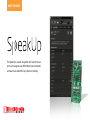
The SpeakUp is a speech recognition click™ board. You can
set it up to recognize over 200 different voice commands
and have the on-board MCU carry them out instantly.
user manual

Page 2
I want to express my thanks to you for being interested in our products and for having
condence in MikroElektronika.
The primary aim of our company is to design and produce high quality electronic products
and to constantly improve the performance thereof in order to better suit your needs.
TO OUR VALUED CUSTOMERS
Nebojsa Matic
General Manager
The STM32® and Windows® logos and product names are trademarks of ST microelectronics® and Microsoft® in the U.S.A. and other countries.

Page 3
1. Introduction 4
2. Applications 5
3. Package Contains 6
4, How to use it? 7
5. Tech Specs 8
6. Schematics 9
7. How It Works? 10
SpeakUp Firwmware Algorithm 11
8. Conguration Through Software 12
8.1. Typical Workow 13
8.2. Getting Started 14
8.3. Creating a new project 15
8.4. New Voice Command 16
8.5. Conguring Project Settings 18
8.6. Assigning An Action 20
8.7. Uploading Project 22
8.8. Exporting Constants 23
9. Direct Conguration 24
10. Recording Tips 25
11. Examples 26
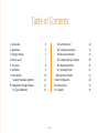
Table of Contents

Page 4
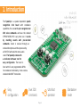
1. Introduction
The SpeakUp is a speaker dependent speech
recognition click board with standalone
capabilities. You can set it up to recognize over
200 voice commands and have the onboard
STM32F415RG MCU carry them out. It works
by matching sounds with pre-recorded
commands. Sound is received through an
onboard microphone and then processed by
a VS1053 IC with a built in stereo-audio
codec. The SpeakUp comes with
a dedicated software tool for
easy configuration. The board is
lined with 12 user programmable GPIOs
for standalone functionality. It also carries a
standard mikroBUS™ host socket.
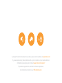
Easy
configuration
Over 200
commands
Ultra fast
operation
Standalone
mode

Page 5
2. Applications
Wouldn't you rather issue verbal commands and have your machines comply, instead of pressing keys, pushing buttons and flipping
switches all the time? There's a wide range of applications for the SpeakUp.
Command your lights, doors and home appliances.
Create voice commanded remotes for TVs or media centers.
Reduce complexity and cost of control interfaces.
When doing something with both hands and voice command is the only option.

Page 6
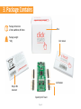
3. Package Contains
Package dimensions:
L 70mm, W 60mm, H 30mm Box
User manual
1x8 headers
SpeakUp click™ board
Recycle Bin
document
Package weight:
~40g

Page 7
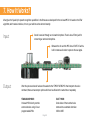
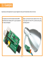
4. How To Use It?
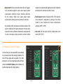
Before using your click™ board on your target platform, make sure to solder 1x8 male headers to both left and right side of the board.
Two 1x8 male headers are included with the board in the package.
Turn the board upside down so that
the bottom side is facing you upwards.
Place shorter pins of the header into
the appropriate soldering pads. Turn the
board upward again. Make sure to align the
headers so that they are perpendicular to
the board, then solder the pins carefully.
Now you need to train your SpeakUp to
obey your commands. Plug in the board
to your PC through USB cable. Configure
it using the free software (see page 12).
Alternatively you can configure the board
directly using the on-board buttons (see
page 24).
1. Prepare it 2. Configure it
The SpeakUp now understands your
commands. Connect relays, motors or
other electronic actuators directly to
SpeakUp’s GPIO pins. Alternatively plug
the SpeakUp into any board or shield
carrying a mikroBUS™ socket. You can now
control your devices with your voice.
3. Use it

Page 8
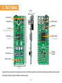
5. Tech Specs
Along with its key components, the SpeakUp packs other useful bits like two buttons for recording or deleting voice commands manually, while
three signal LEDs give recognition feedback and indicate power.
Line out pads
USB connector
Audio jack
Microcontroller
mikroBUS
connector
(STM32415RG)
Microphone
12 GPIOs
25.40 mm
57.15 mm
10.30 mm
(user programmable)
1000 mils
2550 mils
405.50 mils
Audio Codec
(VS1053)
Signal LEDs
Push-buttons
JTAG connector

Page 9
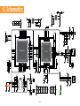
6. Schematics
VCC-USB
C35
2.2uF
R37
39K
R34
287K
1
2
3
IN
GND
OUT5
4
EN ADJ
U4
AP7331-ADJ
C33
10uF
VCC-3.3V
D1
PMEG3010ER
R38
OR
AN
RST
CS
SCK
MOSI
MISO
+3.3V
GND
PWM
INT
RX
TX
SCL
SDA
+5V
GND
MIKROBUS DEVICE CONN.
R3
2K2
LD3
VCC-3.3V
PWM
VCC-USB
FP1
FERRITE
R262201
2
3
4
5GND
ID
D+
D-
VBUS
CN3
USB MINIB
USB-DET
USB-D_N
USB-D_P
INT
UART3-TX
UART3-RX
I2C1-SCL
I2C1-SDA
LEFT
RIGHT
C12
10nF
C10
47nF
C11
10nF
GBUF
C34
2.2uF
2
3
4
5
6
7
11
12
13
14
25
24
23
22
21
18
17
16
15
8
1
19
9
10 27
26
20
28
29
30
31
32
33
34
35
36
37
38
39
40
41
42
43
44
45
46
47
48
MICP/LN1
MICN
XRESET
DGND0
CVDD0
IOVDD0
CVDD1
DREQ
GPIO2
GPIO3
GPIO6
GPIO7
XDCS/BSYNC
IOVDD1
VC0
DGND1
XTAL0
XTAL1
IOVDD2
DGND2
DGND3
DGND4
XCS
CVDD2
GPIO5
RX
TX
SCLK
SI
SO
CVDD3
XTEST
GPIO0
GPIO1
GND
GPIO4
AGND0
AVDD0
AVDD2
AGND1
AGND2
AGND3
LN2
LEFT
RCAP
AVDD1
GBUF
RIGHT
VS1053
U2
1
2
3
IN
GND
OUT5
4
EN ADJ
U3
AP7331-ADJ
R33
100K
R35
27K4
R36
1K
R12
10
R13
10
R14
10
R5 10
R9 10
VCC-1.8VVCC-3.3V
LEFT
RIGHT
GBUF
R23
10K
GPIO
GPIO
R15
10K
VCC-3.3V
R19 27MP3-MISO
MP3-MOSI
MP3-SCLK
MP3-DCS
MP3-DREQ
MP3-RST#
MICN
MP3-CS#
X1
12.288MHz
R24 1M
C19
18pF
C18
18pF
R17
10K
R22
10K
VCC-3.3V
VCC-3.3V VCC-1.8V
R16
1K
R18
1K
VCC-3.3V
MICP
C14 100pF
R7
10
R8
10
MICP
3
1
2
4
6
5
CN2
SJ-43516-SMT
MICN
C16 100pF
C15
100PF
R20
1K
R21
1K
1
2
MIC1
MICROPHONE
30
29
28
27
34
33
58
57
56
55
54
53
52
47
36
35
43
44
45
46
37
38
9
49
50
11
12
32
64
63
4
3
24
23
18
17
16
15
14
13
5
6
7
8
10
1
2
22
21
20
19 62
61
60
59
39
40
41
42
48
31
51
26
25
PC3
PC8
PB1 PD2
PB3
PB2
PA13
PA12
PA11
PA10
PA9
PA8
PC9
PB14
PB12
PB13
PB15
PC7
PC6
VDD
VCAP2
PB4
PC12
PC11
PC10
PA15
PA14
PB9
PB8
BOOT0
PB7
PB6
PB5
VSS
VDD
PC15
PC14
VBAT
PC13
PH0
PH1
NRST
PC0
PC2
PC1
PA2
PA1
PA0
VDDA
VSSA
PB0
PC5
PC4
PA7
PB11
PB10
VDD
VCAP1
VSS
PA3
VDD
PA4
PA5
PA6
STM32F415RG
U1
USB-DET
USB-D_N
USB-D_P
USB-ID
C13
2.2uF
C17
2.2uF
VCC-3.3V
RST#
MP3-MISO
MP3-MOSI
MP3-SCLK
MP3-CS#
SPI1-MISO
SPI1-MOSI
SPI1-SCLK
SPI1-CS#
SPI1-MISO
SPI1-MOSI
SPI1-SCLK
SPI1-CS#
I2C1-SCL
I2C1-SDA
IO9-PA0
IO8-PA1
IO7-PA2
IO3-PA3
IO2-PB0
IO1-PB1
1
2
3
4
5
6
7
8
HD1
1
2
3
4
5
6
7
8
HD2
VCC-3.3V VCC-3.3V
IO6-PC9
IO5-PC8
IO4-PC7
IO6-PC9
IO5-PC8
IO4-PC7
IO9-PA0
IO8-PA1
IO7-PA2
UART3-TX
UART3-RX
IO12-PC0
IO11-PC1
IO10-PC2
IO12-PC0
IO11-PC1
IO10-PC2
IO3-PA3
IO2-PB0
IO1-PB1
MP3-RST#
MP3-DREQ
MP3-DCS
INT
PWM
C21
100nF
USB-ID
SW1
VCC-3.3V
R25
10K
C20
100nF
SW1-PB10
SW2
VCC-3.3V
R31
10K
C32
100nF
SW2-PD2
LD1LD2
R1
4K7
R2
4K7
LD1-PB2
LD2-PC12
LD1-PB2 LD2-PC12
SW1-PB10
SW2-PD2
R6 470
C8
3.3nF R4
100K
R10470
C9
3.3nF
R11
100K
1
2
3
HD3
R29
10K
R30
10K
R28
10K
VCC-3.3V
VCC-3.3V
C1
100nF
C2
100nF
C3
100nF
C4
100nF
C5
100nF
C6
2.2uF
VCC-3.3V
TMS-SWDIO
TCK-SWCLK
6
8
109
7
5
1 2
3 4
CN4
JTAG
VCC-3.3V
TMS-SWDIO
TCK-SWCLK
RST#
C31
100nF
C30
100nF
C28
100nF
C25
100nF
C29
100nF
C22
100nF
C23
100nF
C24
100nF
C26
100nF
VCC-1.8VVCC-3.3V
C27
100nF
C7
1uF
R
L
G
C38 10uF
C39 10uF
C40
10uF
C41
10uF
C42
10uF
C43
10uF
R39
10K
C44
100nF
RST#

Page 10
7. How It Works?
Input:
Output:
What gives the SpeakUp its speech recognition capabilities is the firmware we developed for the on-board MCU. It’s based on the DTW
algorithm, which makes it decisive, it turns your talk into action almost instantly.
Sound is received through an on-board microphone. There’s also a 3.5mm jack for
connecting an external microphone.
After the processed sound has been forwarded to the STM32F415RG MCU that interprets the voice
command, there are two output options which can be utilized at the same time or separately:
STANDALONE MODE:
On-board MCU directly controls
external devices using 12 user
programmable GPIOs
CLICK™ MODE:
Sends index of the matched voice
command to a selectable interface:
USB or UART.
Between the mic and the MCU sits a VS1053 IC with a
built in stereo audio codec to process the raw signal.

Page 11
The main goal of a speech recognition system is to substitute a human listener, although it is very difficult for an artificial system to achieve
the flexibility offered by human ear and human brain. The work principle of speech recognition systems is roughly based on the comparison of
input data to prerecorded patterns. These patterns can be arranged in the form of phoneme or word. By this comparison, the pattern to which
the input data is most similar is accepted as the symbolic representation of the data. It is very difficult to compare raw speech signals directly.
Because the intensity of speech signals can vary significantly, a preprocessing on the signals is necessary. This preprocessing is called Feature
Extraction.
First, short time feature vectors are obtained from the input speech data, and then these vectors are compared to the patterns classified
prior to comparison. The feature vectors extracted from speech signal are required to best represent the speech data, to be in size that can be
processed efficiently, and to have distinct characteristics.
The SpeakUp Firmware uses Dynamic Time Warping (DTW) algorithm - word-based, isolated word, speaker dependent and template matching
algorithm :
In the word based speech recognition the smallest recognition unit is a word
In the isolated word recognition, words that are uttered with short pauses are recognized,
Speaker dependent reference patterns are constructed for a single speaker,
Template matching algorithm is a form of pattern recognition. It represents speech data as sets of feature/parameter vectors called
templates. Each word or phrase in an application is stored as a separate template. The input speech is then compared with stored
templates and the stored template most closely matching the incoming speech pattern is identified as the input word or phrase.
SpeakUp Firmware Algorithm

Page 12
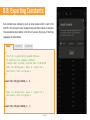
http://www.mikroe.com/downloads/get/2077/
speakup_app.zip
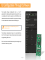
8. Conguration Through Software
The SpeakUp software configuration tool is a free PC
application for configuring the SpeakUp click board. With it, you
can configure the board to recognize over 200 different voice
commands and have the on-board MCU carry them out instantly.
You can download the software from the following link:
The software is designed with ease of use and simplicity in
mind. The UI is based on tabs and drop-down menus requiring
no programming skills to use.
Still, it has all the essential features and options that give you
full control of the set-up process.

Page 13
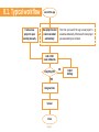
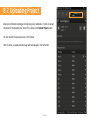
8.1. Typical workow
First time you launch the app a new project is
created automatically. Otherwise, the last project
you were working on will open.
Launch the app
Close
Add or Edit
voice commands
Upload
Assign actions
Adjust
Settings
New project created
or last one loaded
automatically
Create a new
project or open
existing manually
Everything OK? NO
YES

Page 14
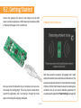
8.2. Getting Started
Connect the SpeakUp click board to the computer via the USB
cable. It will be recognized as a USB Human Interface Device (HID)
in the Device Manager of the Control Panel.
After the successful connection, the SpeakUp click™ board
will perform ambient noise detection and calibrate itself. The
process lasts about 10 seconds. It’s done when the red signal
LED turns off. After that the board is ready for recording voice
commands. You can set custom calibration parameters for
any subsequent usage in the Project Settings (see page 18).
Ambient Noise Detection
Once you connect the SpeakUp to your computer you’re just a few
clicks away from configuring it. The set-up process is dead simple.
Launch the application, and it will lead you through the initial
steps of recording and assigning commands.

Page 15
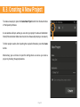
8.3. Creating A New Project
To create a new project, press the Create New Project button from the main toolbar
of the SpeakUp software.
A new window will open, where you can enter your project’s name and destination
folder (if the destination folder doesn’t exist, the software will prompt you to create it).
To finish project creation after inputting the required information, press the Create
button.
Alternatively, you can choose to open the settings menu as soon as you create a
project, by checking the appropriate box.

Page 16
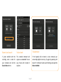
8.4. New Voice Command
To record a new voice
command, press the Add New
Voice Command button.
A New Voice Comand dialog
window will appear. Press the
Record button.
The length of the recording
is set in the Project Settings
window (see page 18).
The recorded command will be
played back automatically, so
you can make sure it’s OK.
Add a voice command Record it Stay within the time limit Hear it back

Page 17
If you’re satisfied with the
recording, enter a name for
your command and click the
Save & Close button.
The recorded command will
appear as a new tab. You can
play it back, edit or delete it
anytime.
If the SpeakUp fails to detect a voice command, your
surrounding might be too noisy. Try again by speaking a bit
louder. If it still doesn’t work, launch Settings and adjust the
Noise treshhold.
Troubleshoot
Name it and save it You’re done!

Page 18
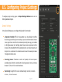
8.5. Conguring Project Settings
General Settings
To configure project settings, press the Open Settings Window button and the
Settings window will open.
In the General Settings you can configure the SpeakUp’s functionality:
Acceptance threshold: This is the parameter you should adjust to define
how closely your delivery has to match your pre-recorded command. At lower
values, you’ll have to deliver the command precisely the way you recorded
it. At higher values the matching doesn’t have to be so precise, but this
increases the probability that the SpeakUp will pick up irrelevant speech and
interpret it as a command. You should be able to reach the sweet spot value
through some trial & error.
Recording timeout: Timeframe in which the SpeakUp click board expects
recording input after the record button is being pressed. User can choose
between 5, 10 and 15 seconds timeframes.
Word Length: Length of the voice command being recorded, in seconds.
Can be 1, 1.5 and 2 seconds.

Page 19
Noise level: Minimal sound volume level that can trigger a
voice command recognition. Lower values require quieter
pronunciation, resulting in higher noise/hiss sensitivity.
On the contrary, higher level values require louder
pronounciation and they are less sensitive to noise/hiss.
We recommend that you keep auto detection enabled. That
way the SpeakUp Click board will measure the noise level,
and perform noise calibration automatically. Auto detection
can last a bit longer, usually around 10 seconds. Sudden
changes in sound levels will lengthen the time of calibration
and will result in improper sound level values.
Notify master: Notifies the master (MCU or PC) when the
voice command is recognized by sending a 16-bit index
number of voice command via chosen communication
interface (UART or USB).
Data rate: Sets the speed used for sending data to the
master (MCU or PC).
Pin Aliases And Initial Pin States
In this section, you can rename GPIO pins according
to your needs and set their starting conditions. The
new GPIO pin aliases will be applied in the main
window too. Set the corresponding initial GPIO pin
state in the Initial Pin States section. Condition can
be either low (logical 0) or high (logical 1).

Page 20
8.6. Assigning An Action
When a new command is recorded, it is time to assign it an action. The action will be
performed when the voice command is recognized. Also, a 16-bit index number of the
voice command will be sent via chosen communication interface (UART or USB) .
NONE: When this option is selected, no action will be performed on the
corresponding GPIO pin upon voice command matching.
ON: When this option is selected, a corresponding GPIO pin will be set to logical
high state upon voice command matching.
OFF: When this option is selected, a corresponding GPIO pin will be set to logical
low state upon voice command matching.
TOGGLE: When this option is selected, a corresponding GPIO pin state will be
toggled upon voice command matching.
PULSE: When this option is selected, a train of pulses will be sent to the
corresponding GPIO pin upon voice command matching.
There are five types of action that can be assigned :
Page is loading ...
Page is loading ...
Page is loading ...
Page is loading ...
Page is loading ...
Page is loading ...
Page is loading ...
Page is loading ...
-
 1
1
-
 2
2
-
 3
3
-
 4
4
-
 5
5
-
 6
6
-
 7
7
-
 8
8
-
 9
9
-
 10
10
-
 11
11
-
 12
12
-
 13
13
-
 14
14
-
 15
15
-
 16
16
-
 17
17
-
 18
18
-
 19
19
-
 20
20
-
 21
21
-
 22
22
-
 23
23
-
 24
24
-
 25
25
-
 26
26
-
 27
27
-
 28
28


mikroElektronika MIKROE-1534 User manual
- Type
- User manual
- This manual is also suitable for
Ask a question and I''ll find the answer in the document
Finding information in a document is now easier with AI
Related papers
-
Mikroe MIKROE-5134 User manual
-
mikroElektronika mikromedia 7 Schematics
-
-
-
-
-
-
-
mikroElektronika MIKROE-1718 User manual
-
Other documents
-
Mikroe GTS-511E2 User manual
-
-
audiophony T50690 User manual
-
-
Microchip Technology SAMA5D2-PTC-EK User manual
-
Mikroe 23LC1024 Operating instructions
-
-
-
ST STM32091C-EVAL User manual
-
 Dialog DA14531 USB Development Kit Hardware UM-B-125 User manual
