Mikroe GTS-511E2 User manual

Type
User manual

Mikroe GTS-511E2 is a click board solution for adding biometric security to your designs. It features the GTS-511E2 module, the thinnest optical touch fingerprint sensor in the world, which resists 2D fakes and can be used to record real fingerprints. The board also carries an STM32 MCU for processing the images and forwarding them to an external MCU or PC. Fingerprint click™ can communicate with the target board MCU through UART (TX, RX) or SPI (CS, SCK, MISO, MOSI) lines and is designed to use a 3.3V power supply.

Mikroe GTS-511E2 is a click board solution for adding biometric security to your designs. It features the GTS-511E2 module, the thinnest optical touch fingerprint sensor in the world, which resists 2D fakes and can be used to record real fingerprints. The board also carries an STM32 MCU for processing the images and forwarding them to an external MCU or PC. Fingerprint click™ can communicate with the target board MCU through UART (TX, RX) or SPI (CS, SCK, MISO, MOSI) lines and is designed to use a 3.3V power supply.

2 3
click
BOARD
www.mikroe.com
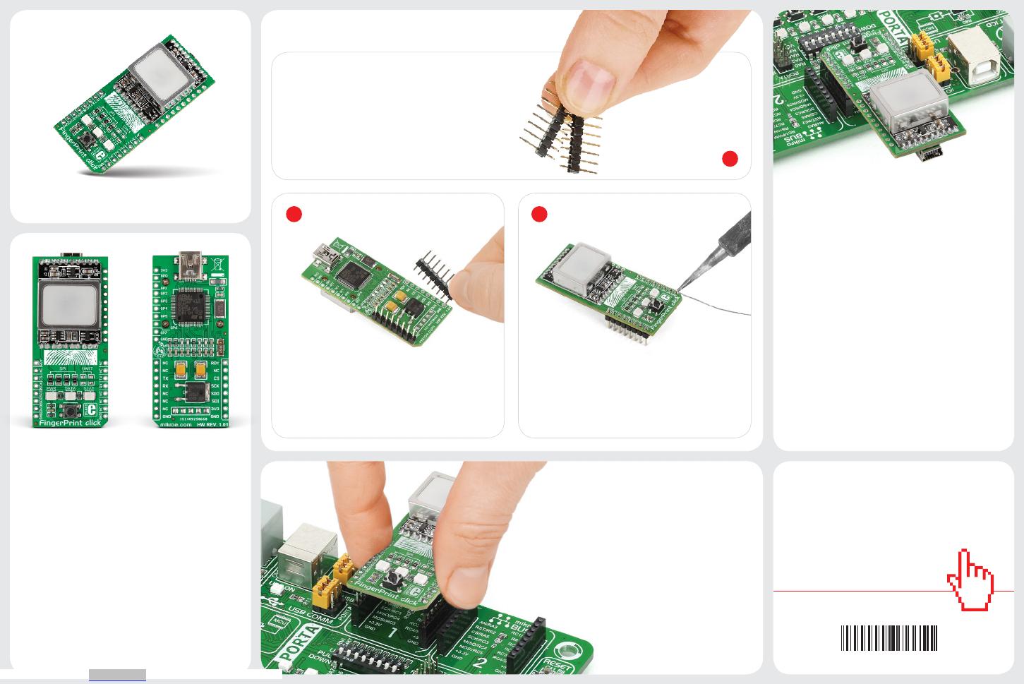
2. Soldering the headers
3. Plugging the board in
Once you have soldered the headers your
board is ready to be placed into the desired
mikroBUS socket. Make sure to align the
cut in the lower-right part of the board with
the markings on the silkscreen at the
mikroBUS socket. If all the
pins are aligned correctly,
push the board all the way
into the socket.
Turn the board upward again. Make sure
to align the headers so that they are
perpendicular to the board, then solder the
pins carefully.
Turn the board upside down so that
the bottom side is facing you upwards.
Place shorter pins of the header into the
appropriate soldering pads.
Before using your click board, make sure
to solder 1x8 male headers to both left and
right side of the board. Two 1x8 male headers
are included with the board in the package.
4. Essential features
Fingerprint click can communicate with the
target board MCU through UART (TX, RX) or
SPI (CS, SCK, MISO, MOSI) lines. However
it also carries a mini USB connector for
connecting the click board to a PC — which
will generally be a more suitable platform for
developing ngerprint recognition software,
due to the processing powers required for
comparing and matching inputs to a large
database of existing images. The board is also
lined with additional GPIO pins giving more
access to the onboard STM32. Fingerprint
click is designed to use a 3.3V power supply.
1
Fingerprint click is a click board solution
for adding biometric security to your design.
It carries the GTS-511E2 module, which
is the thinnest optical touch ngerprint
sensor in the world. The module comprises
a CMOS image sensor with a special lens and
covering that records real ngerprints while
resitsing 2D fakes. The click board also
carries an STM32 MCU for processing the
images and forwarding them to an external
MCU or PC.
Fingerprint click
1. Introduction
FINGERPRINT click manual
ver 1.01
0100000076651
Downloaded from Arrow.com.
X1
16MHz
X2
32.768KHz
C4
22pF
C2
22pF
C6
22pF
C5
22pF
C3
2.2uF
C8
2.2uF
C9
100nF
C10
100nF
C11
100nF
C12
100nF
C13
100nF
C14
2.2uF
VDD- 3.3V
VDD- 3.3V
LD3 LD1LD2
R3
4K7
R4
4K7
PC12_LD1
PC13_LD2
R5
2K2
VCC- USB
FP1 1
2
3
4
5GND
ID
D+
D-
VBUS
CN1
USB MINIB
USB-DET
USB-D_N
USB-D_P
USB-ID
R6
220
C7
100nF
VDD- 3.3V
E1
10uF
E2
10uF
3
1
2
GND
Vin
Vout
REG1
LD29080DT33
VCC- USB VDD- 3.3V
30
29
28
27
34
33
58
57
56
55
54
53
52
47
36
35
43
44
45
46
37
38
9
49
50
11
12
32
64
63
4
3
24
23
18
17
16
15
14
13
5
6
7
8
10
1
2
22
21
20
19 62
61
60
59
39
40
41
42
48
31
51
26
25
PC3
PC8
PB1 PD2
PB3
PB2
PA13
PA12
PA11
PA10
PA9
PA8
PC9
PB14
PB12
PB13
PB15
PC7
PC6
VDD
VCAP2
PB4
PC12
PC11
PC10
PA15
PA14
PB9
PB8
BOOT0
PB7
PB6
PB5
VSS
VDD
PC15
PC14
VBAT
PC13
PH0
PH1
NRST
PC0
PC2
PC1
PA2
PA1
PA0
VDDA
VSSA
PB0
PC5
PC4
PA7
PB11
PB10
VDD
VCAP1
VSS
PA3
VDD
PA4
PA5
PA6
STM32F415RG
U1
PC13_LD2
OSC32_IN
OSC32_OUT
RST#
READY#
PA0_D0
PA1_D1
PA2_D2
PA3_D3
PA4_D4
PA5_D5
PA6_D6
PA7_D7
PC4_HSY
PC5_VSY
PB0_LED
PB1_PWD
GPIO6
GPIO7
PC8_CS#
PB13_SCK
PB14_MISO
PB15_MOSI
GPIO0
GPIO1
TMS-SWDIO
TCK-SWCLK
GPIO2
PC10_TX
PC11_RX
GPIO3
GPIO4
PA8_PWM
PC1_RST#
I2C1_SCL
I2C1_SDA
PB8_PCLK
GPIO5
USB-DET
USB-D_N
USB-D_P
USB-ID
OSC_IN
OSC_OUT
NC
D5
D6
D7
SCL
SDA
VSYNC
HSYNC
RSTB
PWDN
D4
PCLK
D3
D2
D1
D0
LED
MCLK
GND
VCC
U2
GTS-511E2
AN
RST
CS
SCK
MOSI
MISO
+3.3V
GND
PWM
INT
RX
TX
SCL
SDA
+5V
GND
MIKROBUS DEVICE CONN
PA5_D5
PA6_D6
PA7_D7
I2C1_SCL
I2C1_SDA
PC4_HSY
PC5_VSY
PC1_RST#
PB1_PWD
PA4_D4
PA3_D3
PA2_D2
PA1_D1
PA0_D0
PB8_PCLK
PB0_LED
PA8_PWM
VDD- 3.3V
R8
4K7
R7
4K7
VDD-3.3V VDD-3.3V
I2C1_SCL
I2C1_SDA
1
2
J1
1
2
J5
1
2
J3
1
2
J6
1
2
J4
1
2
J2
VDD- 3.3V
PC10_TX
PC11_RX
PB13_SCK
PB15_MOSI
PB14_MISO
PC8_CS#
READY#
READY#
MCU_MISO
MCU_SCK
CS#
MCU_MOSI
MCU_RX
MCU_TX
T1
VDD-3.3V
R1
10K
C1
100nF
R2
220
RST#
RESET
TCK-SWCLK
JTAG
TMS-SWDIO
RST#
VDD- 3.3V
5
4
3
1
2
CN4
GPIO0
GPIO1
GPIO2
GPIO3
GPIO4
GPIO5
GPIO6
GPIO7
5
4
3
1
2
6
7
8
9
10
CN5
VDD- 3.3V
SPI2 INTERFACE
PC12_LD1
USART3 INTERFACE
R9
4K7
VDD- 3.3V
PC8_CS#
8. Code examples
MikroElektronika oers free tech support
(www.mikroe.com/support) until the end of
the product’s lifetime, so if something goes
wrong, we’re ready and willing to help!
Once you have done all the necessary
preparations, it’s time to get your click board
up and running. We have provided examples
for mikroC, mikroBasic and mikroPascal
compilers on our Libstock website. Just
download them and you are ready to start.
.com
6. Dimensions
MikroElektronika assumes no responsibility
or liability for any errors or inaccuracies
that may appear in the present document.
Specication and information contained in
the present schematic are subject to change
at any time without notice.
Copyright © 2015 MikroElektronika.
All rights reserved.
mm mils
LENGTH 58.25 2293
WIDTH 25.4 1000
HEIGHT* 14.14 557
5. Schematic
7. Windows app
9. Support
* without headers
10. Disclaimer
We created a Windows application that
provides an easy interface for communicating
with Fingerprint click. The code is available on
Libstock so you can use it as a starting point
for developing more sophisticated software.
Alternatively, the DLL les that control the
onboard module are also available, so you can
develop your own app from scratch.
25.4 mm / 1000 mils
58.25 / 2293 mils
Downloaded from Arrow.com.Downloaded from Arrow.com.
  • Page 1 1
  • Page 2 2

Mikroe GTS-511E2 User manual

Type
User manual

Mikroe GTS-511E2 is a click board solution for adding biometric security to your designs. It features the GTS-511E2 module, the thinnest optical touch fingerprint sensor in the world, which resists 2D fakes and can be used to record real fingerprints. The board also carries an STM32 MCU for processing the images and forwarding them to an external MCU or PC. Fingerprint click™ can communicate with the target board MCU through UART (TX, RX) or SPI (CS, SCK, MISO, MOSI) lines and is designed to use a 3.3V power supply.

Ask a question and I''ll find the answer in the document

Finding information in a document is now easier with AI