Page is loading ...

USER'S GUIDE
EasyPIC
connectivity
v7
Supports 3.3V and 5V devices
Dual Power Supply
Easy-add extra boards
mikroBUS
™
sockets
Four connectors for each port
Amazing Connectivity
microcontrollers supported
The ultimate PIC
®
board
Fast USB 2.0 programmer and
In-Circuit Debugger

From the day one, we in MikroElektronika gave ourselves the highest possible goals in pursuit of excellence.
That same day, the idea of EasyPIC
™
development board was born. And we all grew together with EasyPIC
™
.
In its each and tiniest piece we had put all of our energy, creativity and sense of what’s best for an engineer.
I’ve personally assembled hundreds of early EasyPIC
™
boards myself with my home soldering iron.
Today, we present you the 7th generation of the board, which brings us some exciting new features. We hope
that you will like it as much as we do.
Use it wisely and have fun!
To our valued customers
Nebojsa Matic,
Owner and General Manager
of MikroElektronika

Table of contents
page 3
DS1820 - Digital Temperature Sensor . . . . . . . . . . . . . .
LCD 2x16 characters . . . . . . . . . . . . . . . . . . . . . . . . . . . . . .
Introduction . . . . . . . . . . . . . . . . . . . . . . . . . . . . . . . . . . . . . . .
What’s Next? . . . . . . . . . . . . . . . . . . . . . . . . . . . . . . . . . . . . . .
I2C EEPROM . . . . . . . . . . . . . . . . . . . . . . . . . . . . . . . . . . . . . .
mikroBUS
™
sockets . . . . . . . . . . . . . . . . . . . . . . . . . . . . . . . .
Installing programmer drivers . . . . . . . . . . . . . . . . . . . . . .
4 digit 7-seg display . . . . . . . . . . . . . . . . . . . . . . . . . . . . . .
LM35 - Analog Temperature Sensor . . . . . . . . . . . . . . . .
GLCD 128x64. . . . . . . . . . . . . . . . . . . . . . . . . . . . . . . . . . . . .
It's good to know . . . . . . . . . . . . . . . . . . . . . . . . . . . . . . . . . .
Piezo Buzzer . . . . . . . . . . . . . . . . . . . . . . . . . . . . . . . . . . . . . .
Input/Output Group . . . . . . . . . . . . . . . . . . . . . . . . . . . . . . .
Programming software . . . . . . . . . . . . . . . . . . . . . . . . . . . .
ADC inputs . . . . . . . . . . . . . . . . . . . . . . . . . . . . . . . . . . . . . . . .
On-board programmer . . . . . . . . . . . . . . . . . . . . . . . . . . . . .
Dual power supply . . . . . . . . . . . . . . . . . . . . . . . . . . . . . . . .
Supported microcontrollers . . . . . . . . . . . . . . . . . . . . . . . .
Touch panel controller . . . . . . . . . . . . . . . . . . . . . . . . . . . . .
Additional GNDs . . . . . . . . . . . . . . . . . . . . . . . . . . . . . . . . . . .
Introduction
Power Supply
Supported MCUs
Programming
Displays
Modules
What’s Next
Connectivity
28
24
04
34
31
19
12
27
29
25
05
32
22
13
mikroICD
™
- In Circuit Debugger . . . . . . . . . . . . . . . . . . . .
14
30
10
06
08
26
33
UART via RS-232 . . . . . . . . . . . . . . . . . . . . . . . . . . . . . . . . .
UART via USB . . . . . . . . . . . . . . . . . . . . . . . . . . . . . . . . . . . . .
USB connection . . . . . . . . . . . . . . . . . . . . . . . . . . . . . . . . . . .
Communication
16
17
18

Introduction
introduction
page 4
EasyPIC
™
is an old friend. It has been with us for six generations. Many of
us made our rst steps in embedded world with EasyPIC
™
. Today it has
thousands of users: students, hobbyists, enthusiasts and professionals.
It’s used in many schools and other educational institutions across the
globe. We may say that it’s the most famous PIC development system
in the world. We asked ourselves what we can do to make such a great
board even greater. And we made some brilliant changes. We focused
all of our creativity and knowledge into making a revolutionary new
design, unlike any previous version of the board. We now present
you with the new version 7 that brings so much more, and we
hope that you will be thrilled with your new board, just as we are.
EasyPIC
™
development Team
EasyPIC
™
v7 is all about
connectivity. Having four
dierent connectors for
each port, you can connect
accessory boards, sensors and
your custom electronics easier
then ever before.
Powerful on-board mikroProg
™
programmer and In-Circuit
debugger can program
and debug over 350
microcontrollers. You will
need it, whether you are a
professional or a beginner.
Four connectors for each port Everything is already here
Amazing connectivity mikroProg
™
on board
EasyPIC
™
v7 is among few
development boards which
support both 3.3V and 5V
microcontrollers. This feature
greatly increases the number of
supported MCUs. It’s like having
two boards instead of one!
3.3V and 5V power supply
Dual Power Supply
Just plug in your Click
™
board,
and it’s ready to work. We
picked up a set of the most
useful pins you need for
development and made a
pinout standard you will
enjoy using.
For easier connections
mikroBUS
™
support

It's good to know
Package contains
introduction
page 5
System Specication
PIC18F45K22 is the new default microcontroller!
power supply
7–23V AC or 9–32V DC
or via USB cable (5V DC)
board dimensions
266 x 220mm (10.47 x 8.66 inch)
weight
~445g (0.981 lbs)
power consumption
~85mA when all peripheral
modules are disconnected
Damage resistant
protective box
EasyPIC
™
v7 board in
antistatic bag
USB cable User Manuals and
Board schematic
1 2 3 4
Until now, EasyPIC
™
development boards were equipped
with PIC16
®
as the default chip. Now we are giving you more
power than ever before. PIC18F45K22 is the new default
chip of EasyPIC
™
v7! It has 16 MIPS operation, 32K bytes of
linear program memory, 1536 bytes of linear data memory,
and support for a wide range of power supply from 1.8V to
5V. It’s loaded with great modules: 36 General purpose I/O
pins, 30 Analog Input pins (AD), Digital-To-Analog Converter
(DAC), support for Capacitive Touch Sensing using Charge
Time Measurement Unit (CTMU), three 8-bit timers and four
16-bit timers. It also has pair of CCP, Comparators and
MSSP modules (which can be either SPI or I
2
C).
- More power than ever before
- Great choice for both beginners
and professionals
- Rich with modules
- Enough RAM and Flash
- Comes with examples for
mikroC, mikroBasic and
mikroPascal compilers
We present you with a complete color schematics for EasyPIC ™ v7 development board. We wanted
to make electronics more understandable, even for absolute beginners, so we provided photos of
most used SMD components, and made additional comments and drawings so you can get to know
what your board is consisted of, and how it actually works.

Dual power supply
Board contains switching power supply
that creates stable voltage and
current levels necessary for
powering each part of the
board. Power supply section
contains two power regulators:
MC34063A, which generates
VCC-5V, and MC33269DT3.3 which
creates VCC-3.3V power supply. The board
can be powered in three dierent ways: with USB
power supply (CN2), using external adapters via adapter
connector (CN31) or additional screw terminals (CN30). External
adapter voltage levels must be in range of 9-32V DC or 7-23V AC. Use
jumper J6 to specify which power source you are using and jumper J5 to specify
whether you are using 5V or 3.3V power supply. Upon providing the power using
either external adapter or USB power source you can turn on power supply by using SWITCH 1
(Figure 3-1). Power LED (Green ON) will indicate the presence of power supply.
Figure 3-2: Dual power supply unit schematic
Figure 3-1: Dual power supply unit of EasyPIC
™
v7
1
2
3
4
8
7
6
5
SWC
SWE
CT
GND
DRVC
IPK
VIN
CMPR
U3
MC34063A
R65
0.22
R34
3K
VCC-SW
C8
220pF
D1
MBRS140T3
L2 220uH
E1
220uF/35V LESR
VCC-EXT
R35
1K
VCC-5V
J6
2
1
3
SWITCH1
VCC-USB
VCC-SW
D12
1N4007
D13
1N4007
D15
1N4007
D14
1N4007
J5
VCC-5V
VCC-BRD
VCC-3.3
C14
100nF
VCC-5V
2
1
3
GND
Vout
Vin
REG1
MC33269DT3.3
E7
10uF
VCC-3.3
CN31
CN30
VCC-5V
R66
2K2
LD37
E2
220uF/35V LESR
E4
10uF
VCC-USB
L4
FERRITE
C19
100nF
1
2
3
4
VCC
GND
CN2
USB
3.3V VOLTAGE REGULATOR
5V SWITCHING POWER SUPPLY
E6
220uF/35V LESR
VCC-5V
power supply
page 6

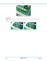
How to power the board?
power supply
To power the board with USB cable, place jumper J6 in
USB position and place jumper J5 in 5V or 3.3V position.
You can then plug in the USB cable as shown on images
1
and
2
, and turn the power switch ON.
To power the board via adapter connector, place jumper
J6 in EXT position, and place jumper J5 in 5V or 3.3V
position. You can then plug in the adapter cable as shown
on images
3
and
4
, and turn the power switch ON.
To power the board using screw terminals, place jumper
J6 in EXT position, and place jumper J5 in 5V or 3.3V
position. You can then screw-on the cables in the screw
terminals as shown on images
5
and
6
, and turn the
power switch ON.
EasyPIC
™
v7 development board supports both
3.3V and 5V power supply on a single board.
This feature enables you to use wide range of
peripheral boards.
Set J6 jumper to
USB position
Set J6 jumper to
EXT position
1. With USB cable
3. With laboratory power supply
Set J6 jumper to
EXT position
2. Using adapter
1
3
5
2
4
6
page 7
Power supply: via DC connector or screw terminals
(7V to 23V AC or 9V to 32V DC),
or via USB cable (5V DC)
Power capacity: up to 500mA with USB, and up to 600mA
with external power supply

supported MCUs
Supported
microcontrollers
The board contains eight DIP sockets: DIP40, DIP28, DIP20, DIP18A, DIP18B, DIP14,
DIP8 and support for PIC10F MCUs. With dual power supply and smart on-board
mikroProg, board is capable of programming over 350 microcontrollers from PIC10F,
PIC12F, PIC16F, PIC16Enh, PIC18F, PIC18FJ and PIC18FK families.
There are two DIP18 sockets for PIC microcontrollers provided on the board - DIP18A
and DIP18B. Which of these sockets you will use depends solely on the pinout of
the microcontroller in use. The EasyPIC
™
v7 development system comes with the
PIC18F45K22 microcontroller in a DIP40 package.
DIP40 DIP18A
DIP28
C33
100nF
VCC-MCU
C9
100nF
VCC-MCU
C12
100nF
VCC-MCU
C13
100nF
VCC-MCU
C10
100nF
VCC-MCU
E14
10uF
VCC-MCU
VCC-MCU VCC-MCU
VCC-MCU
1
2
3
4
5
6
7
8
9
10
11
12
13
14
15
16
17
18
19
20 21
22
23
24
25
26
27
28
29
30
31
32
33
34
35
36
37
38
39
40
DIP SKT 40
1
2
3
4
5
6
7
8
9 10
11
12
13
14
15
16
17
18
DIP SKT 18
1
2
3
4
5
6
7
8
9
10
11
12
13
14 15
16
17
18
19
20
21
22
23
24
25
26
27
28
DIP SKT 28
J20
M1X2
C36
100nF
C35
100nF
C38
100nF
C37
100nF
E11
10uF
E13
10uF
RA5
RA4
RA4
RA5
RA5-DIP28
RA5-DIP40
RA4-DIP40
RA4-DIP28
RA5-DIP28
VCC-MCU
for PIC16F724/727
for PIC18F44J10, PIC18F45J10
for PIC18F24J10, PIC18F25J10
PIC18F2XJ50, PIC18F2XJ11
for PIC16F722/723/726
for PIC18F2331/2431
1
2
3
4 5
6
7
8
DIP SKT 8
1
2
3
4 5
6
7
8
DIP SKT 8
1
2
3
4
5
6
7 8
9
10
11
12
13
14
DIP SKT 14
1
2
3
4
5
6
7
8
9 10
11
12
13
14
15
16
17
18
DIP SKT 18
1
2
3
4
5
6
7
8
9
10 11
12
13
14
15
16
17
18
19
20
DIP SKT 20
DIP20
RA0
RA1
RA2
RA3
RE0
RE1
RE2
RC0
RC1
RC2
RC3-MCU
RD0
RD1
RB7-MCU
RB6-MCU
RB5
RB4
RB3
RB2
RB1
RB0
RD7
RD6
RD5
RD4
RC7
RC6
RC5-MCU
RC4-MCU
RD3
RD2
MCLR-RE3
RA7-MCU
RA6-MCU
RA5-DIP40
RA4-DIP40
RB7-MCU
RB6-MCU
RB2
RB1
RB0
RC7
RC6
RC5-MCU
RC4-MCU
RA0
RA1
RA2
RA3
RC0
RC1
RC2
RC3-MCU
RB5
RB4
RB3
MCLR-RE3
RA7-MCU
RA6-MCU
RA5-DIP28
RA4-DIP28
RA5-MCU
RA4-MCU RA1-MCU
RA0-MCU
RA2-MCU
RC0
RC1
RC2RC3
RC4
RC5
MCLR-RA3
RB4
RB5
RB6RB7
RC7
RC6
VCC-MCU
VCC-MCU
RA0
RA1
RB7-MCU
RB6-MCU
RA3
RA4
RA2
RB2
RB1
RB0
RB5
RB4RB3
MCLR-RA5
RA7-MCU
RA6-MCU
VCC-MCU
DIP18B
RB2
RB3
RB7-MCU
RB6-MCU
RA1
RA4
RA0
RB0
RA3
RA2
RB5
RB4RB1
MCLR-RA5
RA7-MCU
RA6-MCU
RA5-MCU
RA4-MCU RA1-MCU
RA0-MCU
RA2
RC0
RC1
RC2RC3
RC4
RC5
MCLR-RA3
VCC-MCU
RA0-MCU
RA1-MCU
RA5-MCU
RA4-MCU
RA2MCLR-RA3
VCC-MCU
VCC-MCU
RA1-MCU
RA2
RA0-MCU
MCLR-RA3
DIP14
DIP8
10F MCU
C11
100nF
VCC-MCU
C42
100nF
VCC-MCU
C40
100nF
VCC-MCU
C39
100nF
VCC-MCU
J22
J7
J10
J23
X1
8MHz SYS
C6
22pF
C7
22pF
RA7-MCU RA6-MCU
RA7 RA6
J13
RA7-OSC1 RA6-OSC2
X2
8MHz SEC
C22
22pF
C21
22pF
J14
RA4-MCURA5-MCU
RA4RA5
RA4-OSC1RA5-OSC2
X1
8MHz SYS
C6
22pF
C7
22pF
RA7-MCU RA6-MCU
RA7 RA6
J13
RA7-OSC1 RA6-OSC2
X2
8MHz SEC
C22
22pF
C21
22pF
J14
RA4-MCURA5-MCU
RA4RA5
RA4-OSC1RA5-OSC2
VCAP jumpers explained
Some PIC16F, PIC18FK and all PIC18FJ microcontrollers have cores that work
on 1.8V-2.5V voltage range, and peripherals that work with 3.3V and 5V
voltages. Internally, those microcontrollers have power regulators, which adjust
the core voltage levels. In order for those devices to have a stable operation of
the core, manufacturer recommends that decoupling capacitive lters should
be provided, and connected between specic microcontroller pins designated
with VCAP and GND. EasyPIC v7 board provides jumpers which are used for this
purpose. Here is list of devices that require jumpers placed in VCAP position:
VCAP position when using PIC16F724/16F727
VCAP position for PIC18F44J10 and PIC18F45J10
VCAP for PIC18F24J10, PIC18F25J10 PIC18F2XJ50, PIC18F2XJ11
VCAP for PIC16F722, PIC16F723, PIC16F726
IMPORTANT:
If you do not place VCAP jumper for the MCUs that need it,
you might experience some instabilities in program execution.
IMPORTANT: When using PIC18F2331 or PIC18F2431 microcontrollers it is necessary
to place J20 jumper, in order to route VCC power line to RA5 pin (Figure 4-1)
page 8
J7
J22
(see gure 4-1)
J10
J23
Figure 4-2:
crystal
oscillators
Figure 4-1: Schematic of on-board DIP sockets and VCAP jumpers

supported MCUs
Using crystal oscillators
If you want to use microcontrollers in DIP8, DIP14 and DIP20 packages, it is
necessary to put quartz crystal into socket X2 (OSC2). The value of the quartz-
crystal depends on the maximum clock frequency allowed and your application.
You can always exchange the default 8MHz crystal with another one.
Only one microcontroller may be plugged into the development board at the same time.
Before you plug the microcontroller into the
appropriate socket, make sure that the power
supply is turned o. Images above show how to
correctly plug a microcontroller. First make sure that
a half circular cut in the microcontroller DIP packaging
matches the cut in the DIP socket. Place both ends of
the microcontroller into the socket as shown in Figure
4-3. Then put the microcontroller slowly down until
all the pins match the socket as shown in Figure 4-4.
Check again if everything is placed correctly and press
the microcontroller until it is completely plugged into
the socket as shown in Figure 4-5.
Figure 4-6: RA6 and RA7 as I/O pins
(when using internal oscillator)
Figure 4-3: Place both ends of microcontroller on
the socket so the pins are aligned correctly
Figure 4-4: with both ngers, evenly distribute
the force and press the chip into the socket.
Figure 4-5: Properly placed microcontroller will
have equally leveled pins.
Figure 4-7: RA6 and RA7 connected
to X1 quartz-crystal
Figure 4-8: RA4 and RA5 as I/O pins
(when using internal oscillator)
Figure 4-9: RA4 and RA5 connected
to X2 quartz-crystal
How to properly place your microcontroller into the DIP socket?
1
1
2
2
3
3
4
IMPORTANT:
IMPORTANT:
Microcontrollers which are plugged into socket 10F use their own internal oscillator and are not connected to any of the mentioned quartz-crystal sockets.
PIC microcontrollers normally use a quartz crystal for the purpose of providing
clock frequency. The EasyPIC
™
v7 provides two sockets for quartz-crystal.
Microcontrollers in DIP18A, DIP18B, DIP28 and DIP40 packages use socket
X1 (OSC1) for quartz-crystal.
page 9

On-board programmer
What is mikroProg
™
?
How do I start?
programming
mikroProg
™
is a fast USB 2.0 programmer with mikroICD
™
hardware
In-Circuit Debugger. Smart engineering allows mikroProg
™
to support
all PIC10, PIC12, PIC16, PIC18, devices in a single programmer! It
supports over 350 microcontrollers from Microchip
®
. Outstanding
performance and easy operation are among it's top features.
In order to start using mikroProg
™
and program your microcontroller,
you just have to follow two simple steps:
1. Install the necessary software
- Install USB drivers
- Install mikroProg Suite
™
for PIC
®
software
2. Power up the board, and you are ready to go.
- Plug in the programmer USB cable
- LINK LED should light up.
MCLR pin
selection
Programing
lines selection
MCLR pin
function
Before using the programmer,
make sure to set MCLR pin jumpers
J1 and J2, so that MCLR line is
routed to the correct socket for
your microcontroller. If you are
using the default PIC18F45K22,
jumpers are supposed to be set for
DIP40, as shown below.
Jumpers J8 and J9 are
used to select PGC and
PGD programming lines
for your microcontroller.
Make sure to place
jumpers in the proper
position for your socket.
Using jumper J19 you can
specify whether MCLR
pin of your microcontroller
is connected to the on-
board reset circuit, or
acts just as I/O pin.
DIP40,
DIP28,
DIP18A,
DIP18B
MCLR
as
MCLR
DIP20,
DIP14,
DIP8
MCLR
as I/O
DIP40,
DIP28
DIP18A,
DIP18B
DIP20
DIP14
DIP8
Why so many LEDs?
Three LEDs indicate specic programmer
operation. Link LED lights up when USB
link is established with your PC, Active
LED lights up when programmer is active.
Data is on when data is being transferred
between the programmer and PC software
(compiler or mikroProg Suite
™
for PIC
®
).
page 10
NOTE:
If you use other than the default PIC18F45K22 MCU,
make sure that programmer jumpers are placed in proper
positions for your microcontroller socket.

programming
C18
100nF
VCC-BRD
T65
VCC-BRD
R7
10K
R6
1K
C41
100nF
VCC-5VVCC-3.3
LED-DATA
LED-USB
VCC-3.3
LED-ACT
LINK ACTIVE DATA
R67
2K2
R68
4K7
R69
6K8
LD38 LD39 LD40
VCC-USB
L4
FERRITE
C19
100nF
1
2
3
4
VCC
GND
D-
D+
CN2
USB
VCC-BRD
MCU-PGC
MCU-PGD
MCU-VPP
3
4
5
6
1
2
CN28
ICD
MCU-VPP
MCU-PGC
MCU-PGD
BRD-PGC
BRD-PGD
BRD-VPP
VCC-3.3V VCC-5VVCC-BRDVCC-MCU
#RST
USBPROG_P
USBPROG_N
J2 J1
J8 J9
I/O
RE3
RA5
RA3
MCLR-RE3
MCLR-RA5
MCLR-RA3
MCU-VPP
RB6-MCU
RA1-MUX
RB6
RA1
MCU-PGC
BRD-PGC
MCU-PGD
BRD-PGD
RB7-MCU
RA0-MUX
RB7
RA0
J19
BRD-VPP
I/ORST#
DATA BUS
Figure 5-1: mikroProg
™
block schematic
EasyPIC
™
v7 is equipped with RJ-12 connector compatible with
Microchip
®
ICD2
®
and ICD3
®
external programmers. You can
either use the on-board mikroProg
™
programmer or external
programming tools as long as you use only one of them in the
same time. But you still have to set the appropriate jumpers,
as described in the previous page. Insert your ICD programmer
cable into connector CN28, as shown in images
1
and
2
.
1 2
Programming with ICD2/ICD3
page 11

programming
Step 1 - Start Installation
Step 3 - Installing drivers Step 4 - Finish installation
Step 2 - Accept EULA
Installing programmer drivers
In the opened folder you should
be able to locate the driver
setup le. Double click on setup
le to begin installation of the
programmer drivers.
Welcome screen of the installation. Just click on Next
button to proceed.
Drivers are installed automatically in a matter of
seconds.
You will be informed if the drivers are installed correctly.
Click on Finish button to end installation process.
Carefully read End User License Agreement. If you
agree with it, click Next to proceed.
page 12
On-board mikroProg
™
requires drivers in order to work.
Drivers can be found on the link below:
When you locate the drivers, please extract les from
the ZIP archive. Folder with extracted les contains sub
folders with drivers for dierent operating systems.
Depending on which operating system you use, choose
adequate folder and open it.
http://www.mikroe.com/downloads/get/1202/
mikroprog_for_pic_drivers_v200.zip

programming
Step 1 - Start Installation
Step 3 - Install for All users or
current user
Step 5 - Installation in progress
Step 2 - Accept EULA and continue
Step 4 - Choose destination folder
Step 6 - Finish Installation
Programming software
Installation wizard - 6 simple steps
page 13
mikroProg Suite
™
for PIC
®
On-board mikroProg
™
programmer requires special programming software called
mikroProg Suite
™
for PIC
®
. This software is used for programming all of Microchip
®
microcontroller families, including PIC10, PIC12, PIC16, PIC18, dsPIC30/33, PIC24 and
PIC32. Software has intuitive interface and SingleClick
™
programming technology.
To begin, rst locate the installation archive on our website:
After downloading, extract the package and double click the executable setup
le, to start installation.
http://www.mikroe.com/downloads/get/1201/mikroprog_suite_for_pic.zip

programming
mikroICD
™
- In Circuit Debugger
page 14
What is Debugging?
Every developer comes to a point where he has to monitor the
code execution in order to nd errors in the code, or simply
to see if everything is going as planed. This hunt for bugs, or
errors in the code is called debugging. There are two ways
to do this: one is the software simulation, which enables
you to simulate what is supposed to be happening on the
microcontroller as your code lines are executed, and the other,
most reliable one, is monitoring the code execution on the
MCU itself. And this latter one is called In-Circuit debugging.
"In-Circuit" means that it is the real deal - code executes right
on the target device.
What is mikroICD
™
?
The on-board mikroProg
™
programmer supports mikroICD
™
- a
highly eective tool for a Real-Time debugging on hardware
level. The mikroICD
™
debugger enables you to execute your
program on the host PIC microcontroller and view variable
values, Special Function Registers (SFR), RAM, CODE and
EEPROM memory along with the mikroICD
™
code execution
on hardware. Whether you are a beginner, or a professional,
this powerful tool, with intuitive interface and convenient
set of commands will enable you to track down bugs quickly.
mikroICD
™
is one of the fastest, and most reliable debugging
tools on the market.
Supported Compilers
All MikroElektronika compilers, mikroC
™
, mikroBasic
™
and
mikroPascal
™
for PIC
®
, dsPIC
®
and PIC32
®
natively support
mikroICD
™
. Specialized mikroICD
™
DLL module allows compilers
to exploit the full potential of fast hardware debugging.
Along with compilers, make sure to install the appropriate
programmer drivers and mikroProg Suite
™
for PIC
®
programming software, as described on pages 12 and 13.
When you build your project for debugging, and program
the microcontroller with this HEX le, you can start the
debugger using [F9] command. Compiler will change layout
to debugging view, and a blue line will mark where code
execution is currently paused. Use debugging toolbar in
the Watch Window to guide the program execution and
stop anytime. Add the desired variables to Watch Window and
monitor their values. Complete guide to using mikroICD
™
with
your compiler is provided within the EasyPIC
™
v7 package.
How do I use the debugger?
Figure 5-2: mikroICD
™
manual
explains debugging thoroughly
mikroICD
™
in-circuit debugger
Figure 5-3: mikroC PRO for PIC
®
compiler in debugging view, with SFR registers in Watch Window

programming
page 15
Here is a short overview of which debugging commands are supported in MikroElektronika compilers. You can see what each command does,
and what are their shortcuts when you are in debugging mode. It will give you some general picture of what your debugger can do.
Toolbar
Icon
Command Name Shortcut Description
Start Debugger [F9] Starts Debugger.
Run/Pause Debugger [F6] Run/Pause Debugger.
Stop Debugger [Ctrl + F2] Stops Debugger.
Step Into [F7]
Executes the current program line, then halts. If the executed
program line calls another routine, the debugger steps into the
routine and halts after executing the rst instruction within it.
Step Over [F8]
Executes the current program line, then halts. If the executed program
line calls another routine, the debugger will not step into it. The whole
routine will be executed and the debugger halts at the rst instruction
following the call.
Step Out [Ctrl + F8]
Executes all remaining program lines within the subroutine. The
debugger halts immediately upon exiting the subroutine.
Run To Cursor [F4] Executes the program until reaching the cursor position.
Toggle Breakpoint [F5]
Toggle breakpoints option sets new breakpoints or removes those
already set at the current cursor position.
Show/Hide breakpoints [Shift+F4] Shows/Hides window with all breakpoints
Clears breakpoints [Shift+Ctrl+F5] Delete selected breakpoints
Jump to interrupt [F2]
Opens window with available interrupts (doesn't work in mikroICD
™
mode)
mikroICD
™
commands

UART via RS-232
communication
The UART (universal asynchronous
receiver/transmitter) is one of the most
common ways of exchanging data between
the MCU and peripheral components. It is
a serial protocol with separate transmit and
receive lines, and can be used for full-duplex
communication. Both sides must be initialized with
the same baud rate, otherwise the data will not be
received correctly.
RS-232 serial communication is performed through a
9-pin SUB-D connector and the microcontroller UART
module. In order to enable this communication, it
is necessary to establish a connection between
RX and TX lines on SUB-D connector and the
same pins on the target microcontroller using
DIP switches. Since RS-232 communication
voltage levels are dierent than
microcontroller logic levels, it is
necessary to use a RS-232
Transceiver circuit, such as
MAX3232 as shown
on Figure 6-1.
1
2
3
4
5
6
7
8 9
10
11
12
13
14
15
16
C1+
V+
C1-
C2+
C2-
V-
T2OUT
R2IN
T1IN
T2IN
VCC
GND
T1OUT
R1IN
R1OUT
R2OUT
U4
MAX3232
5
9
4
8
3
7
2
6
1
1
5
9
6
CN37
RS232
C28
100nF
C30
100nF
C29
100nF
C31
100nF
E8
10uF
VCC-MCU
RX-232
TX-232
1 2 3 4 5 6 7 8
O
N
SW1
R32
100K
RS232
CONNECTOR
RX-FTDI
RX-232
RX
1 2 3 4 5 6 7 8
O
N
SW2
TX-FTDI
TX-232
TX
RB1
RB4
RB2
RC7
RA3
RB5
RC5
RD7
RB2
RB1
RB5
RC6
RA2
RB7
RC4
RD6
VCC-MCU
VCC-MCU
J3
J4
DATA BUS
Figure 6-1: RS-232 connection schematic
Enabling RS-232
In order to enable RS-232
communication, you must set J3
and J4 jumpers in the RS-232
position, and enable desired RX
and TX lines via SW1 and SW2
DIP switches. For example, if you
want to enable RS-232 connection
on UART1 module of the default
PIC18F45K22 chip, you should
enable SW1.1 (RC7) and SW2.1
(RC6) lines.
page 16

UART via USB
Modern PC computers, laptops and notebooks are
no longer equpped with RS-232 connectors and
UART controllers. They are nowdays replaced with USB
connectors and USB controllers. Still, certain technology
enables UART communication to be done over USB connection.
Controllers such as FT232RL from FTDI
®
convert UART signals
to the appropriate USB standard. In order to use USB-UART module
on EasyPIC
™
v7, you must rst install FTDI drivers on your computer.
Drivers can be found on link bellow:
USB-UART communication is being done through a FT232RL
controller, USB connector (CN32), and microcontroller UART
module. To establish this connection, you must put J3 and
J4 jumpers in the USB-UART position, and connect
RX and TX lines to the appropriate pins of the
microcontroller. This connection is done
using DIP switches SW1 and SW2.
1
2
3
4
5
6
7
8
9
10
11
12
13
14 15
16
17
18
19
20
21
22
23
24
25
26
27
28
TXD
DTR#
RTS#
VCCIO
RXD
RI#
GND
NC
DSR#
DCD#
CTS#
CBUS4
CBUS2
CBUS3
CBUS0
CBUS1
OSCO
OSCI
TEST
AGND
NC
GND
GND
VCC
RESET#
3V3OUT
USBDM
USBDP
FT232RL
U2
FT232RL
VCC-5V
C32
100nF
RX-LED
TX-LED
R9
4K7
R8
2K2
R78
4K7
R79
10K
1
2
3
4
VCC
GND
D-
D+
CN32
USB B
C34
100nF
C50
100nF
E12
10uF
VCC-5VVCC-5V
TX-FTDI
RX-FTDI
USB UA RT
CONNECTOR
TXRX
VCC-MCU VCC-MCU VCC-MCU
VCC-MCU
1 2 3 4 5 6 7 8
O
N
SW1
RX-FTDI
RX-232
RX
1 2 3 4 5 6 7 8
O
N
SW2
TX-FTDI
TX-232
TX
RB1
RB4
RB2
RC7
RA3
RB5
RC5
RD7
RB2
RB1
RB5
RC6
RA2
RB7
RC4
RD6
J3
J4
DATA BUS
Figure 7-1: USB-UART connection schematic
Enabling USB-UART
In order to enable USB-UART
communication, you must set J3
and J4 jumpers in the USB-UART
position, and enable desired RX
and TX lines via SW1 and SW2 DIP
switches. For example, if you want
to enable USB-UART connection
on UART1 module of the default
PIC18F45K22 chip, you should
enable SW1.1 (RC7) and SW2.1
(RC6) lines.
page 17
communication
http://www.ftdichip.com/Drivers/VCP.htm

USB is the acronym for Universal Serial
Bus. This is a very popular industry
standard that denes cables, connectors
and protocols used for communication
and power supply between computers
and other devices. EasyPIC
™
v7 contains
USB connector (CN4) which enables
microcontrollers that support USB
communication to establish a connection
with the target host (eg. PC, Laptop, etc).
Selection of communication lines is done
using jumpers J12 or J18, depending on
the target microcontroller.
When communication lines are
routed from the microcontroller to the
USB connector using mentioned jumpers,
they are cut o from the rest of the
board, and cannot be accessed via PORT
headers.
Dedicated USB ON LED
signalizes the presence of USB connection,
when the USB cable is inserted into the
USB connector.
communication
Figure 8-1:
USB function disabled
Figure 8-2:
USB enabled on PORTC
Figure 8-3:
USB enabled on PORTA
1
2
3
4
VCC
GND
D-
D+
CN4
USB B
USB
CONNECTOR
L44
USB ON
R11
4K7
VCC-3.3
RC3-MCU
RC4-MCU
RC5-MCU
RC3
RC4
RC5
RA2
RA2-MCU
RA1-MUX
RA1-MCU
RA0-MUX
RA0-MCU
PIC18F4550
PIC18F2XJ50
PIC18F1XK50
PIC18LF1XK50
J12
J18
DATA BUS
Depending on your target microcontroller, USB communication can be enabled on
PORTA or PORTC. For PIC18(L)F1XK50 you should put J18 jumpers in the USB
position (Figure 8-3). For PIC18Fxx(J)50, PIC18Fxx(J)53, PIC18Fxx(J)55
and PIC18Fxx58 place J12 jumpers in the USB position (Figure 8-2).
Enabling USB connection
page 18
Figure 8-4: USB connection schematic
(jumpers are in USB disabled position)
USB connection

connectivity
mikroBUS
™
sockets
mikroBUS
™
pinout explained
Easier connectivity and simple conguration are
imperative in modern electronic devices. Success
of the USB standard comes from it’s simplicity of
usage and high and reliable data transfer rates.
As we in MikroElektronika see it, Plug-and-Play
devices with minimum settings are the future in
embedded world too. This is why our engineers
have come up with a simple, but brilliant pinout
with lines that most of today’s accessory boards
require, which almost completely eliminates the
need of additional hardware settings. We called
this new standard the mikroBUS
™
. EasyPIC
™
v7
is the rst development board in the world to
support mikroBUS
™
with two on-board sockets.
As you can see, there are no additional DIP
switches, or jumper selections. Everything is
already routed to the most appropriate pins of
the microcontroller sockets.
mikroBUS
™
host connector
Each mikroBUS
™
host connector consists of
two 1x8 female headers containing pins
that are most likely to be used in the target
accessory board. There are three groups
of communication pins: SPI, UART and I
2
C
communication. There are also single pins
for PWM, Interrupt, Analog input, Reset
and Chip Select. Pinout contains two power
groups: +5V and GND on one header and
+3.3V and GND on the other 1x8 header.
AN - Analog pin
RST - Reset pin
CS - SPI Chip Select line
SCK - SPI Clock line
MISO - SPI Slave Output line
MOSI - SPI Slave Input line
+3.3V - VCC-3.3V power line
GND - Reference Ground
PWM - PWM output line
INT - Hardware Interrupt line
RX - UART Receive line
TX - UART Transmit line
SCL - I2C Clock line
SDA - I2C Data line
+5V - VCC-5V power line
GND - Reference Ground
R90 1K
VCC-3.3V VCC-5V
AN
RST
CS
SCK
MISO
MOSI
3.3V
GND
PWM
INT
RX
TX
SCL
SDA
5V
GND
1
R91 1K
VCC-3.3V VCC-5V
AN
RST
CS
SCK
MISO
MOSI
3.3V
GND
PWM
INT
RX
TX
SCL
SDA
5V
GND
2
RC5
RC4
RC3
RE1
RE0
RA2
RC6
RC7
RC3
RC4
RC0
RB0
RC5
RC4
RC3
RE2
RA5
RA3
RC6
RC7
RC3
RC4
RC1
RB1
DATA BUS
Figure 9-1:
mikroBUS
™
connection
schematic
http://www.mikroe.com/mikrobus/
mikroBUS
™
is not made to be only a part of our development boards. You can freely
place mikroBUS
™
host connectors in your nal PCB designs, as long as you clearly mark
them with mikroBUS
™
logo and footprint specications. For more information, logo
artwork and PCB les visit our website:
Integrate mikroBUS
™
in your design
page 19

connectivity
page 20
Click Boards
™
are plug-n-play!
ADC click
™
LightHz click
™
microSD click
™
DAC click
™
DIGIPOT click
™
SHT1x click
™
MP3 click
™
GSM click
™
RFiD click
™
BlueTooth click
™
MikroElektronika portfolio of over 200 accessory boards is now enriched
by an additional set of mikroBUS
™
compatible Click Boards
™
. Almost each
month several new Click boards
™
are released. It is our intention to provide
the community with as much of these boards as possible, so you will be able
to expand your EasyPIC
™
v7 with additional functionality with literally zero
hardware conguration. Just plug and play. Visit the Click boards
™
webpage
for the complete list of available boards:
http://www.mikroe.com/click/
/