Page is loading ...

DETECTIVE S4CIH7D
DVR security monitoring system with four cameras
User's Manual (EN)

- 82 -
1 Production Introduction
1.1 Product overview
The series DVR is designed especially for security and defense field which is an
outstanding digital surveillance product. It introduces embedded LINUX operating
system which is more stable. It introduces standard H.264mp video compressed
format and G.711A audio compressed format which insures the high quality
image, low error coding ratio and single frame playing. It introduces TCP/IP
network technology which achieves the strong network communication ability
and telecommunication ability.
The series DVR can be used individually or online applied as a part of a safety
surveillance network. With the professional network video surveillance software
it achieves the strong network communication ability and telecommunication
ability.
The series DVR can be applied in the bank, telecom, electric power system,
judicial system, transportation, intelligent housing, factory, storehouse, water
conservancy and so on.
1.2 Main functions
Real-time surveillance
spot interface, analog interface, VGA interface and HDMI interface,
surveillance function through monitor or display.
Storage
non-working hard disk dormancy processing which is convenient to
radiate heat, reduce power and extend the life-span
special storage format which insures the data safety
Compression
real-time compression by individual hard disk which insures the audio
and video signal stable synchronization
Backup

- 83 -
through USB interface such as USB equipment, removable hard disk
and so on
through net download the files in the hard disk
Playback
individual real-time video recording as well as searching, playback,
network surveillance, recording check, downloading and so on
multi-playback mode
zoom at arbitrary region
Net operating
through net tele-surveillance in the real time
tele-PTZ control
tele-recording check and real-time playback
Alarm linkage
Alarm activated video record, tour ,message, buzzer, e-mail, ftp
Communication interface
RS485 interface which fulfills the alarm input and PTZ control
Intelligent operating
mouse action function
fast copy and paste operating for the same setting
2 Open-package check and cable connections
2.1 Open-package check
Front panel and rear panel
The key function specification in the front panel and the interface
specification in the real panel are in the specification.
Please check the product type in the front panel whether is accordant
with the product type you order.
The label in the real panel is very important for the after service. Please
protect it carefully. When you contact us for after service, please provide the

- 84 -
product type and serial number in the label.
2.2 Hard disk installation
For the first use, please install the hard disk, this machine box can install two
hard disk (no limited capacity).
For the first use,please install the hard disk.
1. Remove case screw 2. Remove cover 3. Install SATA hard disk
4. Connect SATA data cable 5. Connect SATA power cable 6. Replace cover
7. Replace screws
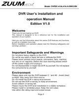
2.3 Front panel

- 85 -
(1) IR remote receiver
(2) Power indicator light
(3) Previous file
(4) HDD indicator light
(5) Next file
(6) PTZ
(7) Slow play
(8) HDD Info
(9) Fast play
(10) Backward pause
(11) Record
(12) Play and Pause
(13) Function switch
(14) Search video
(15) USB
(16) ESC
(17) Left
(18) Up
(19) Down
(20) Menu/Enter
(21) Right
2.4 Rear panel
(1) Video input
(2) Video output
(3) Audio input
(4) Audio output
(5) Power
(6) RS-485
(7) RJ-45
(8) USB
(9) HDMI
(10) VGA

- 86 -
2.5 Full Connectivity Diagram
2.6 Audio and video input and output connections
2.6.1 Video input connections
The video input port is BNC connector plug. The demand of input signal is
PAL/NTSC BNC(1.0V
P-P
,75Ω).
The video signal must be accorded with the state standard which has the high
signal to noise ratio, low aberration and low interference. The image must be
clear and has natural color in the appropriate brightness.
Insure the video signal stable and credible
The video should be installed in the appropriate location where is away from
backlighting and low illumination or adopts the better backlighting and low
illumination compensation.
The ground and power supply of the video and the DVR should be shared and
stable.
Insure the transmission line stable and credible
The video transmission line should adopt high quality coaxial pair which is
chosen by the transmission distance. If the transmission distance is too far, it
should adopt shielded twisted pair, video compensation equipment and

- 87 -
transmit by fiber to insure the signal quality.
The video signal line should be away from the electromagnetic Interference
and other equipments signal lines. The high voltage current should be avoided
especially.
Insure the connection stable and credible
The signal and shield lines should be firm and connected credible which avoid
false and joint welding and oxidation.
2.6.2 Video output connections and options
The video output is divided into PAL/NTSC BNC(1.0V
P-P
,75Ω) and VGA
output (selective configuration).
When replace the monitor by the computer display, there are some issues to
notice
1. Do not stay in the turn-on state for a long time.
2. Keep the computer display normal working by demagnetizing regularly.
3. Stay away from the electromagnetic Interference.
2.6.3 Audio signal input
Audio port is BNC connection.
The input impedance is high so the tone arm must be active.
The audio signal line should be firm and away from the electromagnetic
Interference and connected credible which avoid false and joint welding and
oxidation. The high voltage current should be avoided especially.
2.6.4 Audio signal output
Commonly the output parameter of DVR audio signal is greater than 200mv
1KΩ(BNC) which can connect the low impedance earphone and active sound
box or other audio output equipments through power amplifier. If the sound
box and the tone arm can not be isolated, howling phenomena is often
existed. There are some methods to deal with the above phenomena.
1. Adopt better directional tone arm.
2. Adjust the sound box volume to be under the threshold that produces
the howling phenomena.

- 88 -
3. Use fitment materials that absorb the sound to reduce reflection of the
sound.
4. Adjust the layout of the sound box and the tone arm.
2.7 PTZ connections
1. PTZ decoder connections
A. The grounding of the PTZ decoder and DVR must be shared otherwise the
common-mode voltage will lead to the PTZ control failure. The shielded
twisted pair is recommended.
B. Avoid the entrance of high voltage. Make the layout reasonably. Take
precaution from the thunder.
C. In the outlying end connect 120Ω resistance paralleled to reduce the
inflection and insure the signal quality.
D. The 485 +/- lines of DVR cannot connected with other 485 output
equipments paralleled.
E. The voltage between the +/- lines of the decoder must be less than 5V.
2. Front equipment grounding note
Incorrect grounding can result in damage to the unit.
3. PTZ input type unlimited
Parameter
Meaning
485T+/A, 485T-/B
485communication interface which is connected with the recording
control equipments such as the decoder

- 89 -
3 Basic operation
Note: Any buttons that are displayed in gray indicates it is not supported.
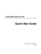
3.1 Preview
Picture3.1 4 Channel Preview
You can right click your mouse to switch between the windows.
The system date, time, channel name, surveillance video, and the alarm
status are shown in each window.
1
Recording status
3
Audio
2
Motion detect
4
Video loss
Table 3.1 Preview icon

- 90 -
3.2 System Login
When the DVR boots up, the user must login and the system provides the
corresponding functions with the user purview. There are two user settings. The
names are admin, default and these names have no password default. admin is
the super user purview; default’s permissions are preview and video playback.
User admin password can be revised, while their permissions can’t be revised;
user default is the default login user whose permission can be revised but not its
password.
Picture 3.1 System Login
Password protection: If the password is continuous wrong three times, the
alarm will start. If the password is continuous wrong five times, the account will
be locked. (Through reboot or after half an hour, the account will be unlocked
automatically).
For your system security, please modify your password after first login.
3.3 Desktop shortcut menu
In preview mode you can right click mouse to get a desktop shortcut menu,as
the picture 3.2 shows. The menu includes: main menu, Guide, record mode,
playback, PTZ control, High Speed PTZ, Alarm Output, color Setting, Output
adjust, Logout, view mode.

- 91 -
Picture 3.2 Shortcut Menu
3.3.1 Main menu
When you login, the system main menu is shown as below.
Picture 3.3 Main Menu

- 92 -
3.3.2 Guide
Include IPONE APP/Android APP download link QR-CODE,and DVR ID number
QR-CODE.
3.3.3 Record Control
Please check current channel status: “○” means it is not in recording status,
“●” means it is in recording status.
You can use desktop shortcut menu or click [main menu]> [recording
function]> [recording set] to enter the recording control interface.
Picture 3.8 Record Mode
【Schedule】Record according to the configuration.
【Manual】Click the all button and the according channel is recording no
matter the channel in any state.

- 93 -
【Stop】Click the stop button and the according channel stops recording no
matter the channel in any state.
3.3.4 Playback
There are two methods for you to play the video files in the hard disk.
1. In the desktop shortcut menu.
Main menu>Record->Playback

- 94 -
Picture 3.4 video playback

- 95 -
(1) Playback
control
(2) Operation hint
(3) Record
mode
(4) Time interval
choosing
(5) Switch by time,
file mode
(6) File searching
(7) Channel
choosing
(8) Date choosing
(9) Storage device
choosing
(10) File
information
(11) Listed
files
(12) Time searching
【Listed files】Look up the listed files that accord with the searching criteria.
【File information】Look up the found file information.
【Playback control】See detail in below chart
Key
Function
Key
Function
/
Play/Pause
Backward play
Slow forward
Fast forward
Previous
frame
Next frame
Previous file
Previous file
Round play
Full screen
Stop
Edit
Backup
Picture 3.5 Playback control key
Note: play under frame by frame, the playback status should be paused
firstly.
【Operation tips】show function of the key that cursor placed.
Special functions:
Accurate playback:Input time (h/m/s) in the time column and then click

- 96 -
play button. The system can operate accurate playback
according to the searching time.
Local zoom: You can drag your mouse in the screen to select a section and
then left click mouse to realize local zoom. Double left click to exit.
Note: The storage drive must be installed before the file can be backed-up.
If the backup is terminated any files already backed-up can be played-back
individually.
Picture 3.6 detect storage device
Detect: Detect the storage device connected to the DVR such as hard drive or
USB drive.
Erasure: Choose the file to delete and click erase to delete the file.
Stop: Stop the backup.
Backup: Click backup button and a dialog box will open. You can choose the
backup file according to the type, channel and time.

- 97 -
Picture 3.7 Recording backup
Remove:Clear file information.
Add:Show file information meeting the set file attributes.
Start/Pause:Click the play button to start the backup and click the pause
button to stop the backup.
Cancel:During backup you can exit the page layout to carry out other
functions.
3.3.5 PTZ control
Operation interface is as followed. The functions include: PTZ direction
control, step, zoom, focus, iris, setup operation, patrol between spots, trail
patrol, boundary scan, assistant switch, light switch, level rotation and so on.
Note
1. Decoder A(B) line connects with DVR A(B)line. The connection is right.
2. Click [main menu] >[system configuration] >[PTZ setup] to set the PTZ
parameters.
3. The PTZ functions are decided by the PTZ protocols.

- 98 -
Picture 3.10 PTZ setup
【Speed】Set the PTZ rotation range. Default range: 1 ~ 8.
【Zoom】Click / button to adjust the zoom multiple of the camera.
【Preset】Click / button to add and delete preset.
【Iris】Click / button to adjust the iris of the camera.
【Hide】Current interface will be temporarily hidden after click it.
【 Direction control 】 Control the PTZ rotation. 8 directions control is
supportive.(4 directions in Front panel is supportive )
【Advance】Tour/pattern/focus/iris/autopan/autoscan.
【PTZ trace】move mouse to control PTZ.
【Page switch】Switch between different pages.
Special functions:
1. Preset
Set a location for the preset, calls the preset points, PTZ automatically
turns to the setting position

- 99 -
Picture 3.11 Preset Settings
2. Tour between Points
Multiple preset points connected cruise lines, call cruise between points,
the PTZ run around on the line
1)Tour Between Points Settings
Tour lines is connected by multiple preset points, setting procedure is as
follows:
Step 1: In Picture 3.12, Click to add one tour, click Settings button to
enter Picture 3.13,
Step 2: In picture 3.13, click to add preset to this
tour, and set time.
Remove Preset:click
Add
preset
Delete
preset
Call
preset
Edit
preset

- 100 -
Picture 3.12 Tour Between Points
Picture 3.13 Tour Between Points Settings
Run one
tour
Tour
Setup
Add tour
Add
preset
Delete
preset
/