Page is loading ...

Medium Voltage SMC OEM Components, 10…15 kV
Bulletin Number 7703E
Installation Instructions
Original Instructions

Important User Information
Read this document and the documents listed in the additional resources section about installation, configuration, and
operation of this equipment before you install, configure, operate, or maintain this product. Users are required to
familiarize themselves with installation and wiring instructions in addition to requirements of all applicable codes, laws,
and standards.
Activities including installation, adjustments, putting into service, use, assembly, disassembly, and maintenance are
required to be carried out by suitably trained personnel in accordance with applicable code of practice.
If this equipment is used in a manner not specified by the manufacturer, the protection provided by the equipment may
be impaired.
In no event will Rockwell Automation, Inc. be responsible or liable for indirect or consequential damages resulting from
the use or application of this equipment.
The examples and diagrams in this manual are included solely for illustrative purposes. Because of the many variables and
requirements associated with any particular installation, Rockwell Automation, Inc. cannot assume responsibility or
liability for actual use based on the examples and diagrams.
No patent liability is assumed by Rockwell Automation, Inc. with respect to use of information, circuits, equipment, or
software described in this manual.
Reproduction of the contents of this manual, in whole or in part, without written permission of Rockwell Automation,
Inc., is prohibited.
Throughout this manual, when necessary, we use notes to make you aware of safety considerations.
Labels may also be on or inside the equipment to provide specific precautions.
WARNING: Identifies information about practices or circumstances that can cause an explosion in a hazardous
environment, which may lead to personal injury or death, property damage, or economic loss.
ATTENTION: Identifies information about practices or circumstances that can lead to personal injury or death, property
damage, or economic loss. Attentions help you identify a hazard, avoid a hazard, and recognize the consequence.
IMPORTANT Identifies information that is critical for successful application and understanding of the product.
SHOCK HAZARD: Labels may be on or inside the equipment, for example, a drive or motor, to alert people that dangerous
voltage may be present.
BURN HAZARD: Labels may be on or inside the equipment, for example, a drive or motor, to alert people that surfaces may
reach dangerous temperatures.
ARC FLASH HAZARD: Labels may be on or inside the equipment, for example, a motor control center, to alert people to
potential Arc Flash. Arc Flash will cause severe injury or death. Wear proper Personal Protective Equipment (PPE). Follow ALL
Regulatory requirements for safe work practices and for Personal Protective Equipment (PPE).

Rockwell Automation Publication 7703E-IN001F-EN-P - July 2019 3
Table of Contents
Preface
Summary of Changes . . . . . . . . . . . . . . . . . . . . . . . . . . . . . . . . . . . . . . . . . . . 5
Scope . . . . . . . . . . . . . . . . . . . . . . . . . . . . . . . . . . . . . . . . . . . . . . . . . . . . . . . . . 5
Additional Resources . . . . . . . . . . . . . . . . . . . . . . . . . . . . . . . . . . . . . . . . . . . 6
Chapter 1
Receiving and General
Information
Receiving . . . . . . . . . . . . . . . . . . . . . . . . . . . . . . . . . . . . . . . . . . . . . . . . . . . . . . 7
Handling Procedures for Electrostatic Sensitive Devices . . . . . . . . . . . 7
Standards and Codes . . . . . . . . . . . . . . . . . . . . . . . . . . . . . . . . . . . . . . . . . . . 7
Chapter 2
PowerBrick Installation Identification . . . . . . . . . . . . . . . . . . . . . . . . . . . . . . . . . . . . . . . . . . . . . . . . . . 9
Sizing the Enclosure . . . . . . . . . . . . . . . . . . . . . . . . . . . . . . . . . . . . . . . . . . . 10
Dimensions. . . . . . . . . . . . . . . . . . . . . . . . . . . . . . . . . . . . . . . . . . . . . . . . . . . 10
Torque Requirements . . . . . . . . . . . . . . . . . . . . . . . . . . . . . . . . . . . . . . . . . 11
PowerBrick Mounting. . . . . . . . . . . . . . . . . . . . . . . . . . . . . . . . . . . . . . . . . 11
Typical Mounting, 10…12 kV PowerBrick System . . . . . . . . . . . . . . . 13
Typical Mounting, 12.1…14.4 kV PowerBrick System. . . . . . . . . . . . 14
Power Connections . . . . . . . . . . . . . . . . . . . . . . . . . . . . . . . . . . . . . . . . . . . 15
Grounding . . . . . . . . . . . . . . . . . . . . . . . . . . . . . . . . . . . . . . . . . . . . . . . . . . . 16
PowerBrick Operating Restrictions . . . . . . . . . . . . . . . . . . . . . . . . . . . . . 16
Voltage Sensing Board Dimensions . . . . . . . . . . . . . . . . . . . . . . . . . . . . . 17
Mounting and Connecting the Voltage Sensing Board. . . . . . . . . . . . 17
Current Loop Gate Drive Power Assembly (CLGD) . . . . . . . . . . . . . 19
Chapter 3
Control Component Installation Interface Board Installation . . . . . . . . . . . . . . . . . . . . . . . . . . . . . . . . . . . . 23
Interface Board Connections. . . . . . . . . . . . . . . . . . . . . . . . . . . . . . . . . . . 25
SMC-50 Control Module. . . . . . . . . . . . . . . . . . . . . . . . . . . . . . . . . . . . . . 25
EMC Compliance. . . . . . . . . . . . . . . . . . . . . . . . . . . . . . . . . . . . . . . . . . . . . 26
Enclosure . . . . . . . . . . . . . . . . . . . . . . . . . . . . . . . . . . . . . . . . . . . . . . . . . 26
Wiring . . . . . . . . . . . . . . . . . . . . . . . . . . . . . . . . . . . . . . . . . . . . . . . . . . . 26
Control Power. . . . . . . . . . . . . . . . . . . . . . . . . . . . . . . . . . . . . . . . . . . . . . . . 27
Control Voltage . . . . . . . . . . . . . . . . . . . . . . . . . . . . . . . . . . . . . . . . . . . 27
Control Wiring . . . . . . . . . . . . . . . . . . . . . . . . . . . . . . . . . . . . . . . . . . . 27
Control Terminal Designations . . . . . . . . . . . . . . . . . . . . . . . . . . . . . . . . 27
Connecting Interface Board to Voltage Sensing Board. . . . . . . . . . . . 28
Connecting Fiber Optic Multiplexer Board to Gate Driver Board . 29
Additional Control Components. . . . . . . . . . . . . . . . . . . . . . . . . . . . . . . 30
Chapter 4
Main and Bypass Switching
Device Installation
Introduction. . . . . . . . . . . . . . . . . . . . . . . . . . . . . . . . . . . . . . . . . . . . . . . . . . 31
Main Contactor or Circuit Breaker . . . . . . . . . . . . . . . . . . . . . . . . . . . . . 31
Bypass Contactor or Circuit Breaker. . . . . . . . . . . . . . . . . . . . . . . . . . . . 31

4 Rockwell Automation Publication 7703E-IN001F-EN-P - July 2019
Table of Contents
Chapter 5
Typical Wiring Diagrams Wiring Diagrams. . . . . . . . . . . . . . . . . . . . . . . . . . . . . . . . . . . . . . . . . . . . . . 33
Chapter 6
Final Test Procedures Final Test Procedures. . . . . . . . . . . . . . . . . . . . . . . . . . . . . . . . . . . . . . . . . . 35
Dielectric Test . . . . . . . . . . . . . . . . . . . . . . . . . . . . . . . . . . . . . . . . . . . . . . . . 36
Additional Tests . . . . . . . . . . . . . . . . . . . . . . . . . . . . . . . . . . . . . . . . . . . . . . 37
Programming . . . . . . . . . . . . . . . . . . . . . . . . . . . . . . . . . . . . . . . . . . . . . . . . . 37
Medium Voltage SMC-50 Module. . . . . . . . . . . . . . . . . . . . . . . . . . 37
Voltage Sensing Module . . . . . . . . . . . . . . . . . . . . . . . . . . . . . . . . . . . . . . . 37
Power Supply Test . . . . . . . . . . . . . . . . . . . . . . . . . . . . . . . . . . . . . . . . . . . . 37
Start-Up. . . . . . . . . . . . . . . . . . . . . . . . . . . . . . . . . . . . . . . . . . . . . . . . . . . . . . 41
Appendix A
Component Deratings Deratings Specifications . . . . . . . . . . . . . . . . . . . . . . . . . . . . . . . . . . . . . . . 43
Appendix B
Typical Schematic Diagrams Introduction. . . . . . . . . . . . . . . . . . . . . . . . . . . . . . . . . . . . . . . . . . . . . . . . . . 45
Appendix C
Spare Parts PowerBricks . . . . . . . . . . . . . . . . . . . . . . . . . . . . . . . . . . . . . . . . . . . . . . . . . . 49
Index
. . . . . . . . . . . . . . . . . . . . . . . . . . . . . . . . . . . . . . . . . . . . . . . . . . . . . . . . 51

Rockwell Automation Publication 7703E-IN001F-EN-P - July 2019 5
Preface
Summary of Changes
Scope
This document pertains to the Bulletin 7703E SMC OEM components for
10…15 kV. These components allow an OEM to fabricate a medium voltage soft
starting solution.
Most of the components described herein are provided in various 7703E kits;
however, some of the devices described are not provided. These must be acquired
separately.
A key part of the Bulletin 7703E components is the power stack assembly which
uses PowerBrick™ technology. PowerBricks are a superior means of packaging
SCRs, heatsinks, passive devices (for circuit protection) and gate drive circuit
boards. Each PowerBrick is a self-contained assembly with inherent insulation
and flexible mounting features. PowerBricks are easily connected in series to
service the required system voltage level.
PowerBricks are provided as a set of components used to create a three-phase
assembly (refer to Figure 1 on page 9
). Each form of PowerBrick assembly is
applied with other Bulletin 7703E control components and power devices, in
forming a complete solution.
Topic Page
Replaced all references from SMC Flex to SMC-50 Throughout
Changed MV Ratio parameter number to 169 18, 37
Replaced dimensions graphic to show updated SMC-50 board 23
Replaced SMC Flex interface board graphic with SMC-50 24
Updated control terminal designations and descriptions 27
Replaced multiplexer board graphic 29
Replaced typical power circuit wiring diagram to reflect SMC-50 interface board 34
Replaced typical power system diagram to reflect SMC-50 interface board 46
replaced typical control circuit graphic to reflect SMC-50 interface board 47

6 Rockwell Automation Publication 7703E-IN001F-EN-P - July 2019
Preface
Additional Resources
These documents contain additional information concerning related products
from Rockwell Automation.
You can view or download publications at
http://www.rockwellautomation.com/global/literature-library/overview.page
.
Resource Description
CENTERLINE Medium Voltage SMC-50 Motor Controller
user manual, publication 1560F-UM001
Provides information on installing, commissioning,
operation, programming, troubleshooting, and
parameter information for MV SMC-50 controllers
Industrial Automation Wiring and Grounding Guidelines,
publication 1770-4.1
Provides general guidelines for installing a Rockwell
Automation industrial system.
Product Certifications website: rok.auto/certifications Provides declarations of conformity, certificates, and
other certification details.

Rockwell Automation Publication 7703E-IN001F-EN-P - July 2019 7
Chapter 1
Receiving and General Information
Receiving
See Getting Started, General Handling Procedures for Medium Voltage
Controllers, publication
MV-QS050. This document is included with your
shipment and contains information regarding receiving, unpacking, initial
inspection, handling, storage, and site preparation.
Handling Procedures for
Electrostatic Sensitive
Devices
To guard against electrostatic damage (ESD) to equipment, the following
precautions should be observed when handling electrostatic sensitive devices.
1. Use a grounding wrist strap to minimize the build up of static charges on
personnel.
2. Handle the module by the edges and avoid touching components or
printed circuit paths.
3. Store devices with sensitive components in the conductive packaging that
the module is shipped in.
These precautions are the minimum requirements for guarding against ESD. For
more information, see Guarding Against Electrostatic Damage, publication
8000-4.5.2
.
Standards and Codes
•CEC (Canadian Electrical Code)
• CSA 22.2 No. 253 (Canadian Standards Association) – Medium Voltage
AC Contactors, Controllers and Control Centers
• NEC (National Electrical Code)
• NEMA ICS Standards (National Electrical Manufacturers’ Association)
ATTENTION: Printed circuit boards contain components that can be damaged
by electrostatic charges that build up on personnel during normal activities.
Exercise the following precautions when handling electrostatic sensitive
devices. Failure to do so may damage the device and render it inoperable.
IMPORTANT It is recommended that the user be familiar with the following safety and
design standards and codes, and any additional local codes that a medium
voltage controller must comply with:

8 Rockwell Automation Publication 7703E-IN001F-EN-P - July 2019
Chapter 1 Receiving and General Information
• OSHA (Occupational Safety and Health Administration)
• UL 50 (Underwriters Laboratories) – Enclosures for Electrical Equipment
• UL 347B (Underwriters Laboratories) – Medium Voltage Motor
Controllers
• UL 508 (Underwriters Laboratories) – Industrial Control Equipment
• IEC 60204-1 – Safety of Machinery – Electrical Equipment of Machines,
Part 1: General Requirements
• IEC 62271-200 – AC Metal Enclosed Switchgear and Control Gear for
Rated Voltages Above 1kV and up to 52 kV (formerly IEC 60298)
• IEC 62271-106 – High Voltage Alternating Current Contactors (formerly
IEC 604701
• IEC 60529 – Degrees of Protection Provided by Enclosures (IP Code)
• IEC 62271-1 – Common Clauses for High Voltage Switchgear and
Control Gear Standards
• ICS1– Industrial Control and Systems General Requirements
• ICS3 Part 2 – Industrial Control and Systems - Medium Voltage
Controllers Rated 2001-7200V AC

Rockwell Automation Publication 7703E-IN001F-EN-P - July 2019 9
Chapter 2
PowerBrick Installation
Identification
A PowerBrick™ is shown in Figure 1.
Figure 1 - Single-phase PowerBrick
Several PowerBricks are supplied as a loose set of components to service a
particular voltage and current. Verify the voltage and current rating of the OEM
power stacks by examining the shipping label and referencing it to the
information in Table 1
.
Table 1 - PowerBrick Options and Catalog Numbers
Catalog Number
(1)
(1) The OEM is responsible for ordering and installing the correct format for the current loop gate drive conductor conduit/CT assembly
(refer to the Installation Instructions, publication 7703E-IN008
for additional details.)
Voltage
(2)
(2) Voltage ranges: 12000 = 10000…12000V (5 PowerBricks in series per phase)
13800 = 12001…14400V (6 PowerBricks in series per phase)
Current (A)
7703E-PPMT 12,000V 3 PH, 50/60 Hz 160
7703E-PPMA 340
7703E-PPMC 580
7703E-PPNT 13,800V 160
7703E-PPNA 340
7703E-PPNC 580

10 Rockwell Automation Publication 7703E-IN001F-EN-P - July 2019
Chapter 2 PowerBrick Installation
In addition to the PowerBricks, a voltage sensing board is to be connected in the
power circuit. Table 2
lists the voltage sensing board catalog numbers.
Table 2 - Voltage Sensing Board Catalog Number
Sizing the Enclosure
Use the data in Table 3 to assist in calculating the enclosure size.
Table 3 - PowerBrick Specifications
Dimensions
See Figure 2, Figure 3, and Figure 4 for PowerBrick dimensions and mounting.
Catalog Number Voltage Sensing Board Input (3 PH, 50/60 Hz)
7703E-VSM 10,000…12,000V
7703E-VSN 12,001…14,400V
ATTENTION: The enclosure for the power stack assemblies must be adequately
sized to provide sufficient airflow to cool the units. Failure to provide adequate
cooling may result in reduced duty cycles or component failure.
Description 160 A, 340 A
Input Voltages
(50/60 Hz)
10,000…12,000V
12,001…14,400V
3 phase, +10%, -15%
Ambient Temperature 0 °C…40 °C (32 °F…104 °F)
Power Section
(for 3 phases)
30 SCR at 10…12 kV
36 SCR at 12.1…14.4 kV
Repetitive Peak Inverse
Voltage Rating
10 to12 kV…32,500 PIV
12.1…14.4 kV…39,000 PIV
Thermal Capacity
(1)
600% of FLA, 10 s
450% of FLA, 30 s
dv/dt Protection R.C. Snubber Network
Maximum Heat
Dissipation (kW)
Start or Stop Cycle (at 450% FLA)
160 A 340 A 580 A Continuous
(2)
10,000…12,000V 27 57 98 0.5
12,001…14,400V 32 69 117 0.5
Altitude 0…1000 m (0…3,300 ft)
(See Controller Deratings Table on page 6, publication 1503-BR010F
)
Net Shipping Weight
(3 PH)
Rating (kV) 10…12 12.1…14.4
Weight kg (lb) 570 (1260) 684 (1512)
(1) It may be possible to offer extended start times at reduced current or ambient temperature. Please consult Rockwell Automation factory for assistance.
(2) After bypass contactor/breaker is closed.

Rockwell Automation Publication 7703E-IN001F-EN-P - July 2019 11
PowerBrick Installation Chapter 2
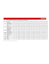
Torque Requirements
All electrical connections must be torqued to the specifications shown in Table 4.
Table 4 - Torque Requirements
PowerBrick Mounting
PowerBricks are to be mounted in a vertical orientation in order to provide
adequate component cooling. Mount the PowerBricks in a suitable location using
the mounting holes provided in the assembly (see Figure 2
). Use M8 (5/16 in.) or
similar hardware for the mounting hole dimensions of 10.7 x 15.9 mm
(0.421 x 0.625 in.).
PowerBricks are provided with two methods for mounting (as shown in
Figure 2
). The PowerBricks can be mounted to a vertical surface using the four
mounting locations on the rear face, or they can be mounted to a horizontal
surface using the four mounting locations on the base.
Note: Using either mounting option requires space above and below each phase
assembly (see Figure 3
and Figure 4).
ATTENTION: Ensure that all electrical connections are torqued to the correct
specification. Failure to do so may result in damage to the equipment and/or
injury to personnel.
Hardware Recommended Torque
¼-20 thread cutting housing assembly screws 7 N•m [62 lb•in]
M5 3.4 N•m [30 lb•in]
Control Wire Terminals 0.2…0.4 N•m [2.0…3.3 lb•in]
CLGD Power Assembly Terminals 5.6 N•m [50 lb•in]
SMC-50 Control Module Terminals 0.6 N•m [5in•lb]
M8, Capacitor Lugs
M8, All others
7.5 N•m [66 lb•in]
14 N•m [120 lb•in]
M10 29 N•m [250 lb•in]
ATTENTION: Maintain sufficient clearance between the power phases and
between phases and grounded surfaces. Refer to local electrical codes to
determine the required clearance. Failure to do so may result in injury to
personnel or damage to the equipment.

12 Rockwell Automation Publication 7703E-IN001F-EN-P - July 2019
Chapter 2 PowerBrick Installation
Figure 2 - Single PowerBrick Dimensions (1000/2400V)
Top View
Front View
Side View
Mounting holes for
M8 [5/16] hardware
(4) places

Rockwell Automation Publication 7703E-IN001F-EN-P - July 2019 13
PowerBrick Installation Chapter 2
Typical Mounting,
10…12 kV PowerBrick
System
Figure 3 - Typical PowerBrick arrangement for 10…12 kV
Front View
Typical spacing to ground metallic enclosure
components. Spacing may be reduced through the
full use of suitable insulation systems.
Side View

14 Rockwell Automation Publication 7703E-IN001F-EN-P - July 2019
Chapter 2 PowerBrick Installation
Typical Mounting,
12.1…14.4 kV PowerBrick
System
Figure 4 - Typical PowerBrick Arrangement for 12.1…14.4 kV
Front View
Typical spacing to ground metallic enclosure
components. Spacing may be reduced through the
full use of suitable insulation systems.
Side View

Rockwell Automation Publication 7703E-IN001F-EN-P - July 2019 15
PowerBrick Installation Chapter 2
Power Connections
1. The PowerBrick units are connected to each other in order to create a
complete phase assembly. The flexible connector on the top of each
PowerBrick is attached to the fixed connector on the bottom of the
PowerBrick above.
2. The top PowerBrick should be connected to a suitable fixed terminal
location. Use appropriate cable lugs to attach suitable line cables to the line
cable terminal. Each PowerBrick can use M10 (3/8 in.) hardware. See
Figure 5
for the terminal location. Torque the fastening hardware to the
specifications shown in Table 4
.
3. Use cable lugs to attach suitable load cables to the load cable terminal
(lower). Refer to Figure 5
for the terminal location. Torque the fastening
hardware to the specifications shown in Ta ble 4
.
4. Refer to Chapter 5
for a typical wiring diagram to determine the required
connections. Appendix B
includes a typical schematic for a complete soft
starter unit.
Figure 5 - Typical Single Phase 15 kV PowerBrick Assembly (side view)
ATTENTION: To avoid shock hazard, lock out incoming power to power cables
when completing connections. Failure to do so may result in severe burns,
injury or death.
IMPORTANT It is the responsibility of the OEM to ensure that suitable line and load cables
are used to satisfy the requirements of the equipment and meet local electrical
codes.
Non-conductive mounting plate
(supplied by OEM)
Insulator
(supplied by OEM)
Flexible bus link
11 mm clearance hole
for M10 hardware
(supplied)
Ter mi na l

16 Rockwell Automation Publication 7703E-IN001F-EN-P - July 2019
Chapter 2 PowerBrick Installation
Figure 6 - Photo of Typical Single Phase PowerBrick Assembly (Front View)
Grounding
PowerBrick Operating
Restrictions
The SCRs in the power stacks are not intended for continuous operation.
Observe the following operating restrictions for the SMC when operating at the
thermal capacity limit and maximum ambient temperature (see Table 3
.)
• Power stacks must be bypassed using a separate contactor or circuit breaker
when the motor is up to speed.
• Do not operate the power stacks for more than 60 seconds in one hour.
• Do not exceed 30 seconds for any individual duty cycle of the power
stacks.
ATTENTION: It is the responsibility of the OEM to ensure that the final enclosure
is suitably bonded to ground, and that provisions for grounding are made
according to local electrical codes and standards.

Rockwell Automation Publication 7703E-IN001F-EN-P - July 2019 17
PowerBrick Installation Chapter 2
• Do not operate the power stacks for at least five minutes between a start or
a stop cycle.
• For repeated hourly operation, forced ventilation is required.
Note: It may be possible to exceed some of the above restrictions if all maximum
ratings are not attained. For example, higher ambient conditions can be
supported when the % FLC and/or start time are reduced. Please consult factory
for details.
Voltage Sensing Board
Dimensions
Figure 7 - Voltage Sensing Board Dimension Diagram
Mounting and Connecting
the Voltage Sensing Board
The voltage sensing board (VSB) for the relevant voltage range (see table below)
should be mounted adjacent to the PowerBrick (see Figure 7
for dimensions). All
connection points are to be made accessible.
ATTENTION: The operating restrictions for the SMC must be adhered to. Failure
to observe the recommended precautions may result in injury to personnel or
damage to the equipment.
8.9 [0.35]
4 holes
Includes features to secure
HV wire for maintained spacings.
Approximate dimensions in mm [inches]
Description Line Voltage
(3 phase, 50/60 Hz)
MV Ratio Catalog Number
Voltage Sensing Board 10,000…12,000V 126 7703E-VSM
12,001…14,400V 97 7703E-VSN

18 Rockwell Automation Publication 7703E-IN001F-EN-P - July 2019
Chapter 2 PowerBrick Installation
Connect the voltage sensing board to the L1 to L3 (Line) and T1 to T3 (Load)
terminals of the power stack (see Figure 8
).
Recommended specifications for wire used on medium voltage connections: UL
style 3239, #18 AWG, 40 KVDC silicone rubber insulated wire, covered with
PCV tubing or other suitable material.
The MV ratios shown above are nominal values and may be fine tuned to achieve
better accuracy on the display of the SMC-50 control module. While running
the motor in bypass mode, compare the voltage displayed on the control module
to a known accurate meter connected to the same source voltage as the motor the
MV SMC-50 is controlling. Parameter 169, MV Ratio, may be changed up or
down to match the HIM display to the external meter. A small change in ratio
can make a large change in the display, so 5 units at a time are recommended.
Increasing the ratio will decrease the displayed voltage, and visa versa.
Figure 8 - Voltage Sensing Board
IMPORTANT The wires must be prevented from touching live or grounded metals, and low
voltage wiring, or have supplemental insulation suitable for the application.
Use the tapered features below the Lx and Tx terminals to maintain wire
spacings in this area.
To Interface Board
Ground Connections

Rockwell Automation Publication 7703E-IN001F-EN-P - July 2019 19
PowerBrick Installation Chapter 2
Current Loop Gate Drive
Power Assembly (CLGD)
The CLGD power assembly is provided as a loose component with the
PowerBricks. It should be mounted adjacent to the PowerBrick in a manner that
allows the secondary cable assembly to be correctly installed.
The CLGD power assembly consists of three parts:
1. Power supply (transformer with secondary terminal blocks and sensing
CT)
2. Current Transformer (CT) assembly (plastic tubing with two current
transformers per PowerBrick)
3. Loop Cable (white, silicone insulated, 50 kV DC, #6 AWG)
The CT assembly is mounted with hardware to the left side of the PowerBrick
stack, and can be pivoted to the left by loosening the mounting hardware to allow
removal of individual PowerBricks without removing the CT assembly. The
current transformer secondary leads plug into the gate driver board directly
behind each CT, and must all be unplugged to pivot the assembly.
Figure 9 - PowerBrick Current Loop Gate Drive Cable Assembly and Power Supply
ATTENTION: Check that all CT leads are plugged into each gate driver board
before putting the SMC into service. Failure to do so may result in erratic
operation and/or equipment damage during option stop maneuvers.

20 Rockwell Automation Publication 7703E-IN001F-EN-P - July 2019
Chapter 2 PowerBrick Installation
Figure 10 - Connection of CLGD CTs to Gate Driver Board
The CT assembly has a loop cable which passes through the tube and connects to
terminal blocks above and/or below the assembly (depending on how the
assembly is implemented). The three phases of loop cables are connected in series
and to the secondary of the power supply transformer. The transformer rating
and secondary voltage are selected to provide 40 or 50 amps in the loop cable.
See Table 5
for matching the loop length to the power supply transformer rating.
See Appendix C
for part numbers.
Table 5 - Matching Loop Length to Power Supply Transformer Rating
CLGD CT
Connection
Terminal
CLGD CTs
CLGD CT
Connection
Ter mi na l
Power Supply Transformer Rating Total Loop Length for #6 AWG Cable
50 VA, 115/230:0.6V 6.4 m ± 10 cm (21 ft ± 4 in.)
100 VA, 115/230:1.5V 15.2 m ± 20 cm (50 ft ± 8 in.)
(1)
(1) The 50 ft length is 3 x 14 ft HV wire plus 8 ft LV wire.
ATTENTION: The loop cable length must be as specified above. The loop cable is
the load for the transformer and establishes the loop current. If it is not correct,
a longer length will not provide sufficient power to the gate driver boards, and a
shorter length will overload the cable or transformer.
/